boot Lancia Musa 2009 Owner handbook (in English)
[x] Cancel search | Manufacturer: LANCIA, Model Year: 2009, Model line: Musa, Model: Lancia Musa 2009Pages: 218, PDF Size: 3.7 MB
Page 8 of 218
7
SAFETY
DEVICES
STARTING
AND
DRIVING
WARNING
LIGHTS AND
MESSAGES
IN AN
EMERGENCY
MAINTENANCE
AND CARE
TECHNICALSPECIFICATIONS
INDEX
DASHBOARD
AND CONTROLSDASHBOARD ........................................................ 8
INSTRUMENT PANEL.......................................... 10
SYMBOLS ............................................................. 11
THE LANCIA CODE SYSTEM .............................. 11
THE KEY AND DOOR LOCKING KIT ................. 13
IGNITION DEVICE .............................................. 20
INSTRUMENTS ................................................... 21
MULTIFUNCTIONAL DISPLAY
(on two-line modal panel) ...................................... 22
MULTIFUNCTIONAL DISPLAY
(on three-line modal panel).................................... 25
ADJUSTING THE SEATS ..................................... 38
HEAD RESTRAINTS ............................................ 44
ADJUSTING THE STEERING WHEEL ............... 45
REARVIEW MIRRORS .......................................... 46
HEATING/CLIMATE CONTROL SYSTEM .......... 47
MANUAL CLIMATE CONTROL SYSTEM ........... 48
AUTOMATIC CLIMATE CONTROL
SYSTEM (TWO-ZONE) ....................................... 52
EXTERNAL LIGHTS ........................................... 62
WINDOW WASHING ............................................ 64
CRUISE CONTROL ............................................. 67CEILING LIGHTS ................................................. 69
LIGHT CONTROL BUTTONS .............................. 71
FUEL CUT-OFF INERTIAL SWITCH ................... 72
INTERNAL EQUIPMENT .................................... 73
SMOKERS KIT ...................................................... 75
SUN VISORS ......................................................... 76
SUNROOF ............................................................ 76
POWER WINDOWS ............................................. 78
BOOT .................................................................... 80
BONNET ............................................................... 82
ROOF BARS .......................................................... 83
HEADLIGHTS ...................................................... 84
ABS SYSTEM ....................................................... 85
EOBD SYSTEM .................................................... 86
SOUND SYSTEM .................................................. 87
ACCESSORIES PURCHASED BY THE OWNER .. 88
“DUALDRIVE” ELECTRIC POWER
STEERING SYSTEM ............................................ 89
PARKING SENSORS ............................................ 90
REFUELLING ...................................................... 92
ENVIRONMENTAL PROTECTION ..................... 94
DASHBOARD AND CONTROLS
007-037 MUSA 1ed GB 10-07-2008 9:36 Pagina 7
Page 43 of 218
42
SAFETY
DEVICES
STARTING
AND
DRIVING
WARNING
LIGHTS AND
MESSAGES
IN AN
EMERGENCY
MAINTENANCE
AND CARE
TECHNICALSPECIFICATIONS
INDEX
DASHBOARD
AND CONTROLS
Rest position on driver’s side
It is the same procedure as above.
However, the headrest must be re-
moved from the seat on the driver’s
side (see paragraph “Headrest” in this
section).
IMPORTANT Refer to section “Boot
Enlargement” for information on the
operations to be carried out with seats
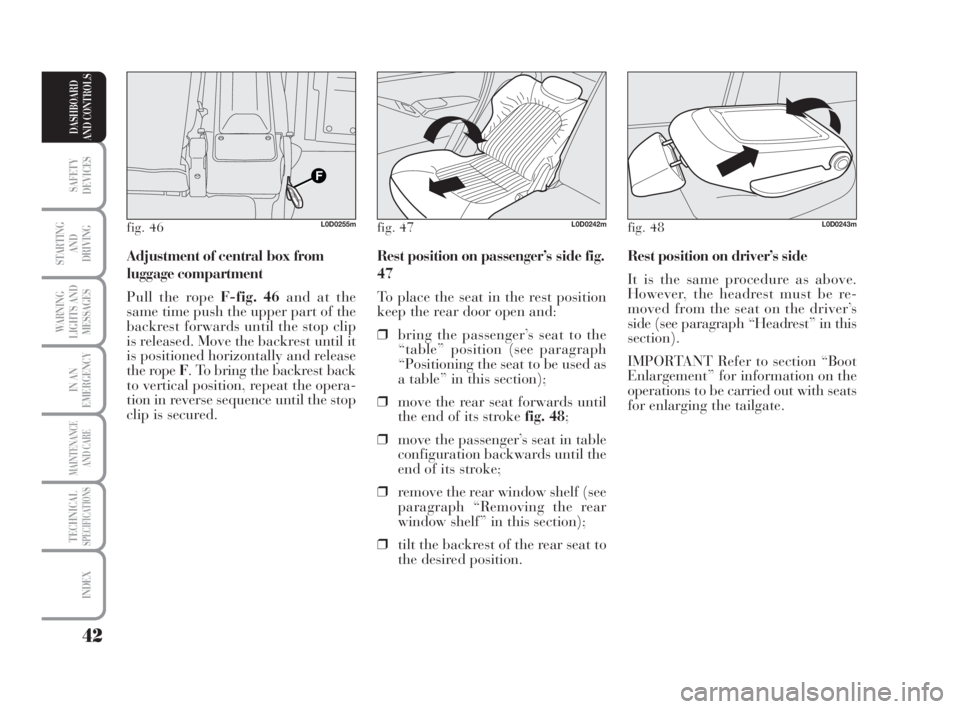
for enlarging the tailgate. Rest position on passenger’s side fig.
47
To place the seat in the rest position
keep the rear door open and:
❒bring the passenger’s seat to the
“table” position (see paragraph
“Positioning the seat to be used as
a table” in this section);
❒move the rear seat forwards until
the end of its stroke fig. 48;
❒move the passenger’s seat in table
configuration backwards until the
end of its stroke;
❒remove the rear window shelf (see
paragraph “Removing the rear
window shelf” in this section);
❒tilt the backrest of the rear seat to
the desired position. Adjustment of central box from
luggage compartment
Pull the rope F-fig. 46and at the
same time push the upper part of the
backrest forwards until the stop clip
is released. Move the backrest until it
is positioned horizontally and release
the rope F. To bring the backrest back
to vertical position, repeat the opera-
tion in reverse sequence until the stop
clip is secured.
fig. 46L0D0255mfig. 47L0D0242mfig. 48L0D0243m
038-094 MUSA 1ed GB 11-07-2008 14:10 Pagina 42
Page 44 of 218
43
SAFETY
DEVICES
STARTING
AND
DRIVING
WARNING
LIGHTS AND
MESSAGES
IN AN
EMERGENCY
MAINTENANCE
AND CARE
TECHNICALSPECIFICATIONS
INDEX
DASHBOARD
AND CONTROLS
Adjusting the central
box and using the ski
compartment
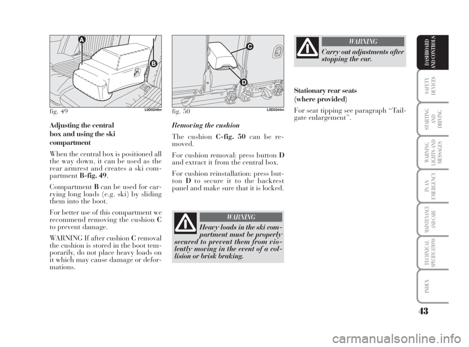
When the central box is positioned all
the way down, it can be used as the
rear armrest and creates a ski com-
partmentB-fig. 49.
CompartmentBcan be used for car-
rying long loads (e.g. ski) by sliding
them into the boot.
For better use of this compartment we
recommend removing the cushion C
to prevent damage.
WARNING If after cushion Cremoval
the cushion is stored in the boot tem-
porarily, do not place heavy loads on
it which may cause damage or defor-
mations.Removing the cushion
The cushion C-fig. 50can be re-
moved.
For cushion removal: press button D
and extract it from the central box.
For cushion reinstallation: press but-
tonDto secure it to the backrest
panel and make sure that it is locked.
fig. 49L0D0249mfig. 50L0D0344m
Heavy loads in the ski com-
partment must be properly
secured to prevent them from vio-
lently moving in the event of a col-
lision or brisk braking.
WARNING
Carry out adjustments after
stopping the car.
WARNING
Stationary rear seats
(where provided)
For seat tipping see paragraph “Tail-
gate enlargement”.
038-094 MUSA 1ed GB 11-07-2008 14:10 Pagina 43
Page 81 of 218
80
SAFETY
DEVICES
STARTING
AND
DRIVING
WARNING
LIGHTS AND
MESSAGES
IN AN
EMERGENCY
MAINTENANCE
AND CARE
TECHNICALSPECIFICATIONS
INDEX
DASHBOARD
AND CONTROLS
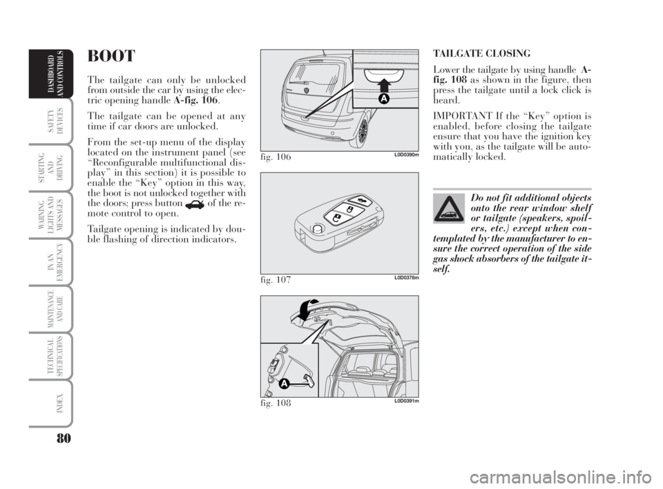
TAILGATE CLOSING
Lower the tailgate by using handleA-
fig. 108as shown in the figure, then
press the tailgate until a lock click is
heard.
IMPORTANT If the “Key” option is
enabled, before closing the tailgate
ensure that you have the ignition key
with you, as the tailgate will be auto-
matically locked.BOOT
The tailgate can only be unlocked
from outside the car by using the elec-
tric opening handle A-fig. 106.
The tailgate can be opened at any
time if car doors are unlocked.
From the set-up menu of the display
located on the instrument panel (see
“Reconfigurable multifunctional dis-
play” in this section) it is possible to
enable the “Key” option in this way,
the boot is not unlocked together with
the doors; press button
Rof the re-
mote control to open.
Tailgate opening is indicated by dou-
ble flashing of direction indicators.
fig. 106L0D0390m
fig. 107L0D0378m
fig. 108L0D0391m
Do not fit additional objects
onto the rear window shelf
or tailgate (speakers, spoil-
ers, etc.) except when con-
templated by the manufacturer to en-
sure the correct operation of the side
gas shock absorbers of the tailgate it-
self.
038-094 MUSA 1ed GB 11-07-2008 14:10 Pagina 80
Page 82 of 218
81
SAFETY
DEVICES
STARTING
AND
DRIVING
WARNING
LIGHTS AND
MESSAGES
IN AN
EMERGENCY
MAINTENANCE
AND CARE
TECHNICALSPECIFICATIONS
INDEX
DASHBOARD
AND CONTROLS
When using the boot, do
not exceed the maximum
admissible loads (see section “Tech-
nical Specifications”). Make sure
that the objects are well arranged in
the boot so that they will not be pro-
jected forwards following sudden
braking.
WARNING
When travelling, do not
put any object on the rear
window shelf. they cause cause in-
jury to passengers in the event of an
accident or sudden braking.
WARNING
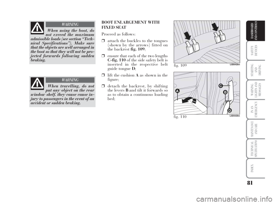
BOOT ENLARGEMENT WITH
FIXED SEAT
Proceed as follows:
❒attach the buckles to the tongues
(shown by the arrows) fitted on
the backrestfig. 109;
❒ensure that each of the two lengths
C-fig. 110of the side safety belt is
inserted in the respective belt
guide tongue D;
❒lift the cushion Aas shown in the
figure;
❒detach the backrest, by shifting
the levers Band tilt it forwards so
as to obtain a continuous loading
bed;
fig. 109L0D0428m
fig. 110L0D0429m
038-094 MUSA 1ed GB 11-07-2008 14:10 Pagina 81
Page 85 of 218
84
SAFETY
DEVICES
STARTING
AND
DRIVING
WARNING
LIGHTS AND
MESSAGES
IN AN
EMERGENCY
MAINTENANCE
AND CARE
TECHNICALSPECIFICATIONS
INDEX
DASHBOARD
AND CONTROLS
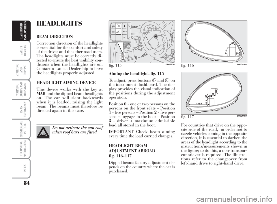
For countries that drive on the oppo-
site side of the road, in order not to
dazzle vehicles coming in the opposite
direction, it is essential to darken the
areas of the headlight according to the
instructions/measurements shown in
the figure; to do this, a non-transpar-
ent sticker is required. The illustra-
tions refer to the changeover from
left-hand drive to right-hand drive. Aiming the headlights fig. 115
To adjust, press buttons
andÒon
the instrument dashboard. The dis-
play provides the visual indication of
the positions during the adjustment
operation.
Position0- one or two persons on the
persons on the front seats – Position
1- five persons – Position 2- five per-
sons + luggage in the boot – Position
3- driver + maximum admissible
load all stored in the boot.
IMPORTANT Check beam aiming
every time the load carried changes.
HEADLIGHT BEAM
ADJUSTMENT ABROAD
fig. 116-117
Dipped beams factory adjustment de-
pends on the country where the car is
purchased.
HEADLIGHTS
BEAM DIRECTION
Correction direction of the headlights
is essential for the comfort and safety
of the driver and the other road users.
The headlights must be correctly di-
rected to ensure the best visibility con-
ditions when the headlights are on.
Contact a Lancia Dealership to have
the headlights properly adjusted.
HEADLIGHT AIMING DEVICE
This device works with the key at
MARand the dipped beam headlights
on. The car will slant backwards
when it is loaded, raising the light
beam. The beams must therefore be
directed again in this case.
Do not activate the sun roof
when roof bars are fitted.
fig. 115L0D0393mfig. 116L0D0118m
fig. 117L0D0119m
038-094 MUSA 1ed GB 11-07-2008 14:10 Pagina 84
Page 119 of 218
118
WARNING
LIGHTS AND
MESSAGES
IN AN
EMERGENCY
MAINTENANCE
AND CARE
TECHNICALSPECIFICATIONS
INDEX
DASHBOARD
AND CONTROLS
SAFETY
DEVICES
STARTING
AND
DRIVING
CONTAINING
RUNNING COSTS
Here are some suggestions which may
help you to keep the running costs of
your car down and lower the amount
of toxic emissions released into the at-
mosphere.
GENERAL CONSIDERATIONS
Car maintenance
Have checks and adjustments carried
out in accordance with the “Service
schedule”.
Tyres
Check tyre pressure regularly at least
once every four weeks: excessively low
pressure will increase consumption
because rolling resistance will be
higher.
Unnecessary loads
Do not travel with an overloaded
boot. The weight of the car (especially
when driving in town) and its trim
greatly affect consumption and sta-
bility.Roof rack/ski rack
Remove the roof rack or the ski rack
from the roof after use. These acces-
sories decrease aerodynamic penetra-
tion of the car and have a negative ef-
fect on consumption. It is better to use
a trailer to transport particularly
bulky objects.
Electric devices
Use electric devices only for the
amount of time needed. Rear heated
window, additional headlights, wind-
screen wipers and heater fan need a
considerable amount of energy, there-
fore increasing the requirement of
current increases fuel consumption
(up to +25% in the urban cycle).
Climate control
The climate control system requires
higher fuel consumption (up to +20%
in average): use the air vents when the
external temperature allows to.
Spoilers
The use of non-certified aerodynamic
items may adversely affect air drag
and consumption levels.DRIVING STYLE
Starting
Do not warm the engine up with the
car standing: the engine warms up
very slowly in these conditions, in-
creasing consumption and emissions.
It is advisable to start off immediately
and slowly keeping the engine speed
down: the engine will warm up much
faster this way.
Unnecessary actions
Avoid revving up when starting at
traffic lights or before stopping the
engine. The latter action, like dou-
bling the clutch, is unnecessary and
causes increase of consumption and
pollution.
Gear selection
Use a higher gear as soon as traffic
and road conditions allow. Using a
low gear for faster acceleration will in-
crease consumption.
In the same way improper use of a
high gear increases consumption,
emissions an engine wear.
113-124 MUSA 1ed GB 10-07-2008 9:37 Pagina 118
Page 139 of 218
138
WARNING
LIGHTS AND
MESSAGES
MAINTENANCE
AND CARE
TECHNICALSPECIFICATIONS
INDEX
DASHBOARD
AND CONTROLS
SAFETY
DEVICES
STARTING
AND
DRIVING
IN AN
EMERGENCY
Indicate that the car is sta-
tionary according to the laws
in force: emergency lights, refracting
warning triangle, etc. Passengers
should leave the car, particularly if it
is very loaded and wait for the wheel
to be changed away from on-coming
traffic. In case of steep slopes or
rough slopes, place wedges or other
materials suitable to stop the vehicle
under the wheels.
WARNINGQUICK TYRE
REPAIR KIT FIX
& GO automatic
(if provided for)
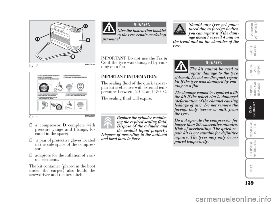
The quick tyre repair kit Fix & Go
automaticfig. 3is placed in the boot.
The kit includes:
❒cylinderAcontaining sealing liq-
uid and fitted with:
– filling pipe B;
– adhesive label Cbearing the
words “max. 80 km/h”, to be at-
tached in a position easily visi-
ble to the driver (on the dash-
board) after tyre repair;
❒informative leaflet fig. 4, used to
ensure the correct use of the quick
tyre repair kit and then given to
the personnel who will handle the
treated tyre; BUMP STARTING
Never jump start the engine by push-
ing, towing or driving downhill. This
could cause a flow of fuel into the cat-
alytic converter and damage it beyond
repair.
IMPORTANT Remember that the
brake booster and the power steering
system are not operating until the en-
gine is started, a greater effort will
therefore be required to press the
brake pedal or turn the steering
wheel.
135-164 MUSA 1ed GB 10-07-2008 9:38 Pagina 138
Page 140 of 218
139
WARNING
LIGHTS AND
MESSAGES
MAINTENANCE
AND CARE
TECHNICALSPECIFICATIONS
INDEX
DASHBOARD
AND CONTROLS
SAFETY
DEVICES
STARTING
AND
DRIVING
IN AN
EMERGENCY
fig. 3L0D0361m
fig. 4L0D0362m
❒a compressor Dcomplete with
pressure gauge and fittings, lo-
cated in the space;
❒a pair of protective gloves located
in the side space of the compres-
sor;
❒adaptors for the inflation of vari-
ous elements.
The kit container (placed in the boot
under the carpet) also holds the
screwdriver and the tow hitch.
Give the instruction booklet
to the tyre repair workshop
personnel.
WARNING
IMPORTANT Do not use the Fix &
Go if the tyre was damaged by run-
ning on a flat.
IMPORTANT INFORMATION:
The sealing fluid of the quick tyre re-
pair kit is effective with external tem-
peratures between –20 °C and +50 °C.
The sealing fluid will expire.
The kit cannot be used to
repair damage to the tyre
sidewall. Do not use the quick repair
kit if the tyre was damaged by run-
ning on a flat.
The damage cannot be repaired with
the kit if the wheel rim is damaged
(deformation of the channel causing
leakage of air). Do not remove the
foreign body (screw or nail) from
the tyre.
Do not operate the compressor for
longer than 20 consecutive minutes.
Risk of overheating. The quick re-
pair kit is not suitable for definitive
repairs. The tyres may only be re-
paired temporarily.
WARNING
Should any tyre get punc-
tured due to foreign bodies,
you can repair it if the dam-
age doesn’t exceed 4 mm on
the tread and on the shoulder of the
tyre.
Replace the cylinder contain-
ing the expired sealing fluid.
Dispose of the cylinder and
the sealant liquid properly.
Dispose of according to the national
and local laws in force.
135-164 MUSA 1ed GB 10-07-2008 9:38 Pagina 139
Page 148 of 218
147
WARNING
LIGHTS AND
MESSAGES
MAINTENANCE
AND CARE
TECHNICALSPECIFICATIONS
INDEX
DASHBOARD
AND CONTROLS
SAFETY
DEVICES
STARTING
AND
DRIVING
IN AN
EMERGENCY
Versions with alloy rims
❒Ensure that the surfaces in contact
with the hub are clean;
❒install the standard wheel by fit-
ting it on the centring pins. Fit the
fastening bolts and screw them
down using the wrench provided;
❒lower the car and remove the jack;
❒using the wrench provided, fully
tighten the bolts in the sequence
shown in fig. 15for the small
spare wheel;
❒refit the snap-fitted hub cap.When you have finished
❒stow the spare wheel in the space
provided in the boot;
❒ fit the jack partially open in its
box, forcing it lightly to prevent it
from vibrating when travelling;
❒put the tools back into their places
in the container;
❒stow the container, complete with
tools, into the spare wheel, screw-
ing in the locking device;
❒put the boot’s stiff preformed in-
sulating mat back in position.WHEN NEEDING
TO CHANGE
A BULB
GENERAL INSTRUCTIONS
❒When a bulb is not working, check
that the corresponding fuse is in-
tact before replacing it: refer to the
“If a fuse blows” paragraph in this
chapter for fuse location;
❒Before changing a bulb check the
contacts for oxidation;
❒burnt bulbs must be replaced by
others of the same type and power;
❒For safety reasons, always check
the height of the headlight beam
after changing a bulb.
Halogen lamps must be han-
dled holding the metallic
part only. Touching the
transparent part of the bulb
with your fingers may reduce the in-
tensity of the emitted light and even
compromise duration of the lamp it-
self. In the event of accidental contact,
rub the bulb with a cloth dampened
with alcohol and allow to dry.
135-164 MUSA 1ed GB 10-07-2008 9:38 Pagina 147