key Lancia Musa 2010 Owner handbook (in English)
[x] Cancel search | Manufacturer: LANCIA, Model Year: 2010, Model line: Musa, Model: Lancia Musa 2010Pages: 218, PDF Size: 3.71 MB
Page 79 of 218
78
SAFETY
STARTING
AND DRIVING
WARNING
LIGHTS AND
MESSAGES
IN AN
EMERGENCY
MAINTENANCE
AND CARE
TECHNICAL
SPECIFICA-
TIONS
INDEX
DASHBOARD
AND
CONTROLS
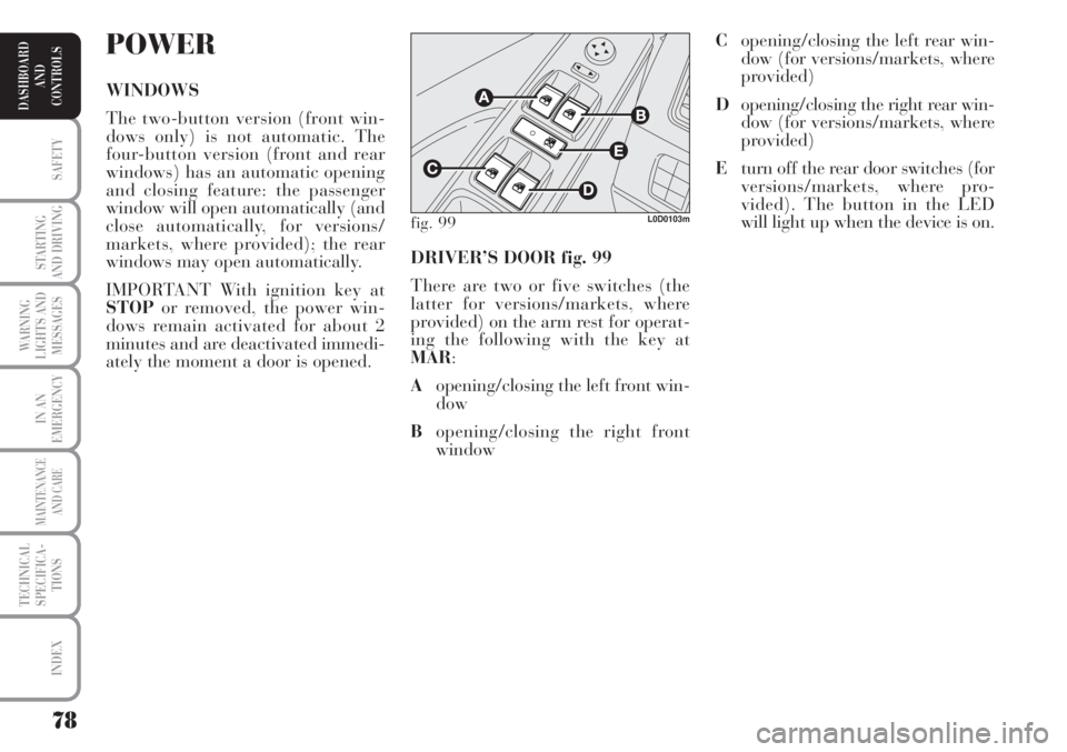
DRIVER’S DOOR fig. 99
There are two or five switches (the
latter for versions/markets, where
provided) on the arm rest for operat-
ing the following with the key at
MAR:
Aopening/closing the left front win-
dow
Bopening/closing the right front
window
POWER
WINDOWS
The two-button version (front win-
dows only) is not automatic. The
four-button version (front and rear
windows) has an automatic opening
and closing feature: the passenger
window will open automatically (and
close automatically, for versions/
markets, where provided); the rear
windows may open automatically.
IMPORTANT With ignition key at
STOPor removed, the power win-
dows remain activated for about 2
minutes and are deactivated immedi-
ately the moment a door is opened.
fig. 99L0D0103m
Copening/closing the left rear win-
dow (for versions/markets, where
provided)
Dopening/closing the right rear win-
dow (for versions/markets, where
provided)
Eturn off the rear door switches (for
versions/markets, where pro-
vided). The button in the LED
will light up when the device is on.
Page 80 of 218
79
SAFETY
STARTING
AND DRIVING
WARNING
LIGHTS AND
MESSAGES
IN AN
EMERGENCY
MAINTENANCE
AND CARE
TECHNICAL
SPECIFICA-
TIONS
INDEX
DASHBOARD
AND
CONTROLS
Automatic continuous operation
(for versions/markets, where provided)
For some versions with four power
windows, the front window (driver’s
side) can be opened and closed auto-
matically while the other windows can
be opened automatically.
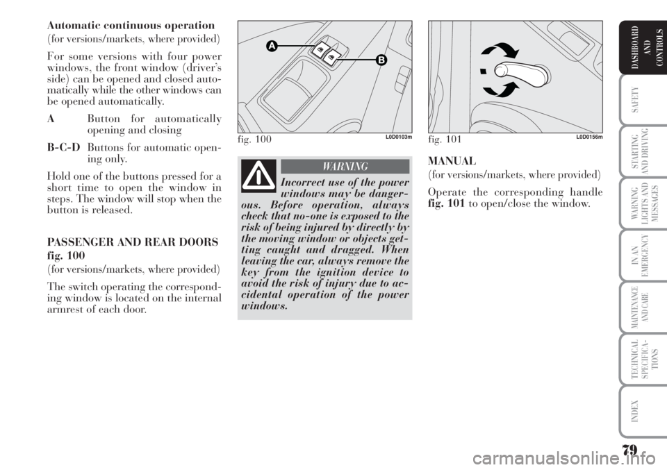
AButton for automatically
opening and closing
B-C-DButtons for automatic open-
ing only.
Hold one of the buttons pressed for a
short time to open the window in
steps. The window will stop when the
button is released.
PASSENGER AND REAR DOORS
fig. 100
(for versions/markets, where provided)
The switch operating the correspond-
ing window is located on the internal
armrest of each door.
fig. 100L0D0103m
Incorrect use of the power
windows may be danger-
ous. Before operation, always
check that no-one is exposed to the
risk of being injured by directly by
the moving window or objects get-
ting caught and dragged. When
leaving the car, always remove the
key from the ignition device to
avoid the risk of injury due to ac-
cidental operation of the power
windows.
WARNING
fig. 101L0D0156m
MANUAL
(for versions/markets, where provided)
Operate the corresponding handle
fig. 101to open/close the window.
Page 81 of 218
80
SAFETY
STARTING
AND DRIVING
WARNING
LIGHTS AND
MESSAGES
IN AN
EMERGENCY
MAINTENANCE
AND CARE
TECHNICAL
SPECIFICA-
TIONS
INDEX
DASHBOARD
AND
CONTROLS
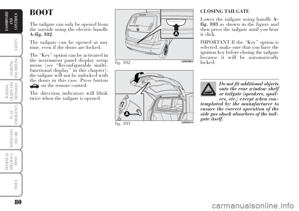
CLOSING TAILGATE
Lower the tailgate using handle A-
fig. 103as shown in the figure and
then press the tailgate until you hear
it click.
IMPORTANT If the “Key” option is
selected, make sure that you have the
ignition key before closing the tailgate
because it will be automatically
locked.BOOT
The tailgate can only be opened from
the outside using the electric handle
A-fig. 102.
The tailgate can be opened at any
time, even if the doors are locked.
The “Key” option can be activated in
the instrument panel display setup
menu (see “Reconfigurable multi-
functional display” in this chapter):
the tailgate will not be unlocked with
the doors in this case. Press button
Ron the remote control.
The direction indicators will blink
twice when the tailgate is opened.
fig. 102L0D0390m
fig. 103L0D0391m
Do not fit additional objects
onto the rear window shelf
or tailgate (speakers, spoil-
ers, etc.) except when con-
templated by the manufacturer to
ensure the correct operation of the
side gas shock absorbers of the tail-
gate itself.
Page 85 of 218
84
SAFETY
STARTING
AND DRIVING
WARNING
LIGHTS AND
MESSAGES
IN AN
EMERGENCY
MAINTENANCE
AND CARE
TECHNICAL
SPECIFICA-
TIONS
INDEX
DASHBOARD
AND
CONTROLS
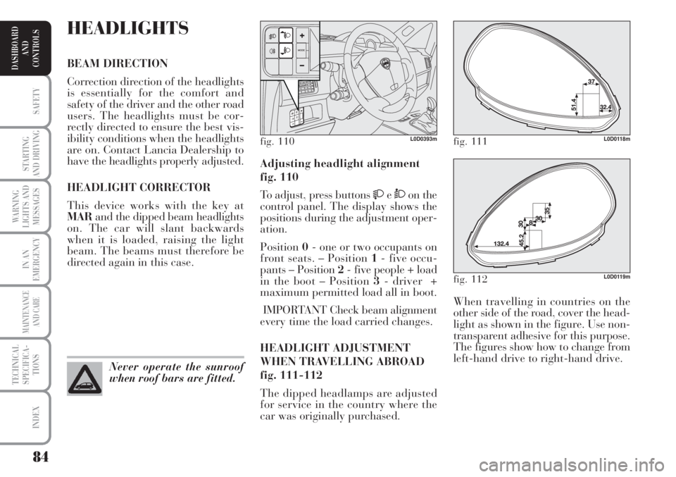
When travelling in countries on the
other side of the road, cover the head-
light as shown in the figure. Use non-
transparent adhesive for this purpose.
The figures show how to change from
left-hand drive to right-hand drive. Adjusting headlight alignment
fig. 110
To adjust, press buttons
eÒon the
control panel. The display shows the
positions during the adjustment oper-
ation.
Position0- one or two occupants on
front seats. – Position 1- five occu-
pants – Position 2- five people + load
in the boot – Position 3- driver +
maximum permitted load all in boot.
IMPORTANT Check beam alignment
every time the load carried changes.
HEADLIGHT ADJUSTMENT
WHEN TRAVELLING ABROAD
fig. 111-112
The dipped headlamps are adjusted
for service in the country where the
car was originally purchased.
HEADLIGHTS
BEAM DIRECTION
Correction direction of the headlights
is essentially for the comfort and
safety of the driver and the other road
users. The headlights must be cor-
rectly directed to ensure the best vis-
ibility conditions when the headlights
are on. Contact Lancia Dealership to
have the headlights properly adjusted.
HEADLIGHT CORRECTOR
This device works with the key at
MARand the dipped beam headlights
on. The car will slant backwards
when it is loaded, raising the light
beam. The beams must therefore be
directed again in this case.
Never operate the sunroof
when roof bars are fitted.
fig. 110L0D0393mfig. 111L0D0118m
fig. 112L0D0119m
Page 87 of 218
86
SAFETY
STARTING
AND DRIVING
WARNING
LIGHTS AND
MESSAGES
IN AN
EMERGENCY
MAINTENANCE
AND CARE
TECHNICAL
SPECIFICA-
TIONS
INDEX
DASHBOARD
AND
CONTROLS
EOBD SYSTEM
The EOBD system (European On
Board Diagnosis) allows continuous
diagnosis of the components of the car
correlated with emissions.
It also alerts the driver, by turning on
the warning light
Uon the instru-
ment panel (together with relevant
message on the multifunctional dis-
play, for versions/markets, where pro-
vided) (see section “Warning lights
and messages”), when these condi-
tions are no longer in peak conditions.
The objective is:
❒to keep the system efficiency under
control;
❒warn when a fault causes emissions
levels to increase;
❒to signal the need to replace deteri-
orated components. In this case, the rear wheels may sud-
denly lock and the car may swerve.
Drive carefully to the nearest Lancia
Dealership to have the system
checked.The system also has a diagnostic con-
nector that can be interfaced with ap-
propriate tools, which makes it possi-
ble to read the error codes stored in
the control unit, together with a series
of specific parameters for engine op-
eration and diagnosis. This check can
also be carried out by the traffic po-
lice.
IMPORTANT After eliminating the
inconvenience, to check the system
completely, Lancia Dealerships are
obliged to run a bench test and, if
necessary, road tests which may also
call for a long journey.
When the ABS cuts in, and
you feel the brake pedal
pulsating, do not remove your foot,
but keep it pressed; in doing so you
will stop in the shortest amount of
space possible under the current
road conditions.
WARNING
If warning light xonly
lights up on the instrument
panel (with a message on the mul-
tifunctional display, for ver-
sions/markets, where provided),
stop the car immediately and go to
the nearest Lancia Dealership.
Leakage of hydraulic fluid from
the braking system will compro-
mise functionality of the braking
system, either of the conventional
type or with ABS.
WARNING
Go to a Lancia Dealership
as soon as possible if warn-
ing light Ueither does not
light up when the key is
turned to MAR to if while travelling
the warning lights comes on either
steady or blinking (along with a
message on the multifunctional dis-
play, where provided). The opera-
tion of warning light Umay be
checked by the traffic police using
specific devices. Follow the laws in
force in the country where you are
driving.
Page 90 of 218
89
SAFETY
STARTING
AND DRIVING
WARNING
LIGHTS AND
MESSAGES
IN AN
EMERGENCY
MAINTENANCE
AND CARE
TECHNICAL
SPECIFICA-
TIONS
INDEX
DASHBOARD
AND
CONTROLS
Fiat Auto S.p.A. authorises the in-
stallation of transceiving devices pro-
vided that they are installed accord-
ing to rules of good engineering prac-
tice respecting the manufacturer’s in-
dications by a specialised centre.
IMPORTANT Traffic police may not
allow the car on the road in the event
of assembly of devices which imply
modifications to the features of the
car. This may also cause lapse of war-
ranty in relation to faults caused by
the change or either directly or indi-
rectly related to it.
Fiat Auto S.p.A. shall not be liable for
damage caused by the installation of
accessories either not supplied or rec-
ommended by Fiat Auto S.p.A.
and/or installed in compliance with
the provided instructions.“DUAL DRIVE”
ELECTRIC POWER
STEERING SYSTEM
The car is provided with an electric
power steering system which only
works with the key at MARand the
engine running. The system called
“Dual drive” allows to customise the
effort required to turn the steering
wheel according to driving conditions.
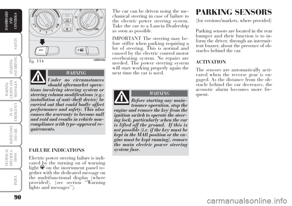
ON/OFF (CITY function)
Press fig. 118in the central part of
the dashboard to turn the function on
and off.
The message CITY appears on the
multifunctional display when the
function is on.
With the CITY function the effort on
the steering wheel is lighter, thus fa-
cilitating parking manoeuvres: this is
particularly useful when driving in
towns. TRANSCEIVERS AND MOBILE
PHONES
Radio transmitter equipment (vehicle
mobile phones, CB radios, amateur
radio etc.) shall not be used inside the
car unless a separate aerial is
mounted on the roof.
IMPORTANT The use of similar de-
vices inside the passenger compart-
ment (without separated aerial) pro-
duces radio-frequency electromag-
netic fields which, amplified by the
resonance effects inside the passenger
compartment, may cause electrical
systems equipping the car to mal-
function. This could compromise
safety in addition to constituting a po-
tential hazard for the passengers.
In addition, transmission and recep-
tion of these devices may be affected
by the shielding effect of the car body.
As concerns EC-approved mobile
phones (GSM, GPRS, UMTS), strictly
comply with the instructions for use
provided by the mobile phone’s man-
ufacturer.
Page 91 of 218
90
SAFETY
STARTING
AND DRIVING
WARNING
LIGHTS AND
MESSAGES
IN AN
EMERGENCY
MAINTENANCE
AND CARE
TECHNICAL
SPECIFICA-
TIONS
INDEX
DASHBOARD
AND
CONTROLS
The car can be driven using the me-
chanical steering in case of failure to
the electric power steering system.
Take the car to a Lancia Dealership
as soon as possible.
IMPORTANT The steering may be-
fore stiffer when parking requiring a
lot of steering. This is normal and
caused by the electric control motor
overheating system. No repairs are
needed. The power steering system
will start working properly again the
next time the car is used. PARKING SENSORS
(for versions/markets, where provided)
Parking sensors are located in the rear
bumper and their function is to in-
form the driver, through an intermit-
tent buzzer, about the presence of ob-
stacles behind the car.
ACTIVATION
The sensors are automatically acti-
vated when the reverse gear is en-
gaged. As the distance from the ob-
stacle behind the car decreases, the
acoustic alarm becomes more fre-
quent.
fig. 114L0D0419m
Under no circumstances
should aftermarket opera-
tions involving steering system or
steering column modifications (e.g.:
installation of anti-theft device) be
carried out that could badly affect
performance and safety. This also
causes the warranty to become null
and void and results in vehicle non-
compliance with type-approval re-
quirements.
WARNING
FAILURE INDICATIONS
Electric power steering failure is indi-
cated by the turning on of warning
light
gon the instrument panel to-
gether with the dedicated message on
the multifunctional display (where
provided), (see section “Warning
lights and messages”).
Before starting any main-
tenance operation, stop the
engine and remove the key from the
ignition switch to operate the steer-
ing lock, particularly when the car
is lifted off the ground. If this is
not possible (i.e. if the key must be
kept in the MAR position or the en-
gine must be kept running), remove
the main electric power steering
system fuse.
WARNING
Page 94 of 218
93
SAFETY
STARTING
AND DRIVING
WARNING
LIGHTS AND
MESSAGES
IN AN
EMERGENCY
MAINTENANCE
AND CARE
TECHNICAL
SPECIFICA-
TIONS
INDEX
DASHBOARD
AND
CONTROLS
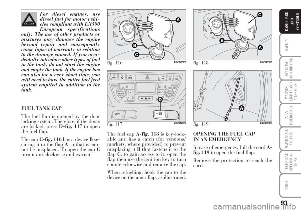
The fuel cap A-fig. 118is key-lock-
able and has a catch (for versions/
markets, where provided) to prevent
misplacing it Bthat fastens it to the
flapC; to gain access to it, open the
flap then use the ignition key to turn
counter-clocwise and remove the cap.
When refuelling, hook the cap to the
device on the inner flap, as illustrated.OPENING THE FUEL CAP
IN AN EMERGENCY
In case of emergency, full the cord
A-
fig. 119to open the fuel flap.
Remove the protection to reach the
cord. For diesel engines, use
diesel fuel for motor vehi-
cles compliant with EN590
European specifications
only. The use of other products or
mixtures may damage the engine
beyond repair and consequently
cause lapse of warranty in relation
to the damage caused. If you acci-
dentally introduce other types of fuel
in the tank, do not start the engine
and empty the tank. If the engine has
run also for a very short time, you
will need to have the entire fuel feed
system emptied in addition to the
tank.
FUEL TANK CAP
The fuel flap is opened by the door
locking system. Therefore, if the doors
are locked, press D-fig. 117to open
the fuel flap.
The cap C-fig, 116has a device Bse-
curing it to the flap Aso that is can-
not be misplaced. To open the cap C
turn it anticlockwise and extract.
fig. 116L0D0399m
fig. 119L0D0490mfig. 117L0D0420m
fig. 118L0D0500m
Page 95 of 218
94
SAFETY
STARTING
AND DRIVING
WARNING
LIGHTS AND
MESSAGES
IN AN
EMERGENCY
MAINTENANCE
AND CARE
TECHNICAL
SPECIFICA-
TIONS
INDEX
DASHBOARD
AND
CONTROLS
late how much particulates has been
trapped by the filter. Since this filter
physically traps particulate, it should
be regenerated (cleaned) at regular in-
tervals by burning carbon particles.
The regeneration procedure is con-
trolled automatically by the engine
management control unit according to
the filter conditions and vehicle use
conditions. The following phenomena
may occur during the regeneration:
limited increase of idle speed, activation
of electric fan, limited increase of
smoke, high temperatures at the ex-
haust. These are not faults; they do not
impair vehicle performance or damage
the environment. If the dedicated mes-
sage is displayed, refer to section
“Warning lights and messages”.PROTECTING THE
ENVIRONMENT
The devices for curtailing petrol engine
emissions are the following:
❒three-way catalytic converter;
❒Lambda sensor;
❒fuel evaporation system.
In addition, do not let the engine run,
even for a test, with one or more spark
plugs disconnected.
The devices for reducing diesel fuel en-
gine emissions are the following:
❒oxidising catalytic converter;
❒exhaust gas recirculation system
(E.G.R.);
❒diesel particulate filter (DPF)
DPF (DIESEL PARTICULATE
FILTER)
(for 1.3 Multijet 90 HP - 1.3 Multijet
95 HP versions)
The Diesel Particulate Filter is a me-
chanical filter, integral with the exhaust
system, that physically traps particu-
lates present in the exhaust gases of
Diesel engines. The diesel particular fil-
ter has been adopted to eliminate al-
most totally particulates in compliance
with current / future law regulations.
During normal use of the vehicle, the
engine control unit records a set of data
(e.g.: travel time, type of route, tem-
peratures, etc.) and it will then calcu- When refuelling, fasten the cap to the
device inside the flap as shown in the
diagram.
IMPORTANT The airtight sealing of
the tank may cause a slight vacuum.
A suction noise when you release the
cap is therefore entirely normal.
After refuelling, fasten the cap by
turning it clockwise until you hear it
click, then turn the key clockwise ad
remove the key from the flap.
Do not approach naked
flames or lit cigarettes to
the fuel filler: fire risk. Keep your
face away from the fuel filler to
prevent breathing in harmful
vapours.
WARNING
The catalytic converter de-
velops high temperature
during operation. Do not park on
grass, dry leaves, pine needles or
other flammable material: fire
risk.
WARNING
Page 98 of 218

97
STARTING
AND DRIVING
WARNING
LIGHTS AND
MESSAGES
IN AN
EMERGENCY
MAINTENANCE
AND CARE
TECHNICAL
SPECIFICA-
TIONS
INDEX
DASHBOARD
AND
CONTROLS
SAFETY
S.B.R. system
The car is fitted with a Seat Belt Re-
minder system (S.B.R.), consisting of
a buzzer and a flashing warning light
must be fastened.
The buzzer can be deactivated (until
the next engine stop) as follows:
❒fasten the driver’s seat belt;
❒turn the ignition key to MAR;
❒wait for over 20 seconds and then
release one of the seat belts.
For permanent deactivation, contact
a Lancia Dealership.
The S.B.R. can only be reactivated us-
ing the setup menu (see the “Warning
lights and messages” chapter, “Seat
belt reminder” paragraph).ADJUSTING THE FRONT SEAT
BELT HEIGHT
(for versions/markets, where provided)
Always adjust the seat belt height to
the passenger’s body: this precaution
may considerably reduce the risk of
injury in the event of a collision.
Correct regulation is obtained when
the belt passes approximately half
way between the shoulder and the
neck.
To adjust, move the grip A-fig. 4of
the locking mechanism either up or
down and at the same time move the
ringBto the most suitable of the al-
lowed positions.
Remember that in the
event of a violent collision,
back seat passengers not wearing
seat belts also represent a serious
danger for the front seat passen-
gers.
WARNING
fig. 4L0D0128m
The height of the seat belts
must be adjusted with the
car at a standstill.
WARNING
After adjustment, always
check that the cursor to
which the ring is fastened is locked
in one of the set positions. Release
the grip and push downwards to
enable the locking device to click if
the grip has not been released in
one of the possible positions.
WARNING