ignition Lancia Musa 2010 Owner handbook (in English)
[x] Cancel search | Manufacturer: LANCIA, Model Year: 2010, Model line: Musa, Model: Lancia Musa 2010Pages: 218, PDF Size: 3.71 MB
Page 135 of 218
134
IN AN
EMERGENCY
MAINTENANCE
AND CARE
TECHNICAL
SPECIFICA-
TIONS
INDEX
DASHBOARD
AND
CONTROLS
SAFETY
STARTING
AND DRIVING
WARNING
LIGHTS AND
MESSAGES
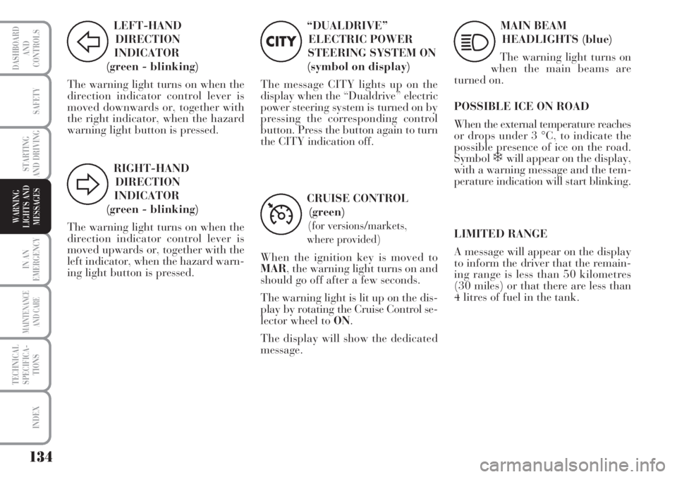
LEFT-HAND
DIRECTION
INDICATOR
(green - blinking)
The warning light turns on when the
direction indicator control lever is
moved downwards or, together with
the right indicator, when the hazard
warning light button is pressed.
F
RIGHT-HAND
DIRECTION
INDICATOR
(green - blinking)
The warning light turns on when the
direction indicator control lever is
moved upwards or, together with the
left indicator, when the hazard warn-
ing light button is pressed.
D
“DUALDRIVE”
ELECTRIC POWER
STEERING SYSTEM ON
(symbol on display)
The message CITY lights up on the
display when the “Dualdrive” electric
power steering system is turned on by
pressing the corresponding control
button. Press the button again to turn
the CITY indication off.
CITY
CRUISE CONTROL
(green)
(for versions/markets,
where provided)
When the ignition key is moved to
MAR, the warning light turns on and
should go off after a few seconds.
The warning light is lit up on the dis-
play by rotating the Cruise Control se-
lector wheel to ON.
The display will show the dedicated
message.
Ü
MAIN BEAM
HEADLIGHTS (blue)
The warning light turns on
when the main beams are
turned on.
POSSIBLE ICE ON ROAD
When the external temperature reaches
or drops under 3 °C, to indicate the
possible presence of ice on the road.
Symbol
❄ will appear on the display,
with a warning message and the tem-
perature indication will start blinking.
1
LIMITED RANGE
A message will appear on the display
to inform the driver that the remain-
ing range is less than 50 kilometres
(30 miles) or that there are less than
4 litres of fuel in the tank.
Page 137 of 218
136
WARNING
LIGHTS AND
MESSAGES
MAINTENANCE
AND CARE
TECHNICAL
SPECIFICA-
TIONS
INDEX
DASHBOARD
AND
CONTROLS
SAFETY
STARTING
AND DRIVING
IN AN
EMERGENCY
OPENING/CLOSING
THE DOORS
Emergency device for opening
the doors from the outside
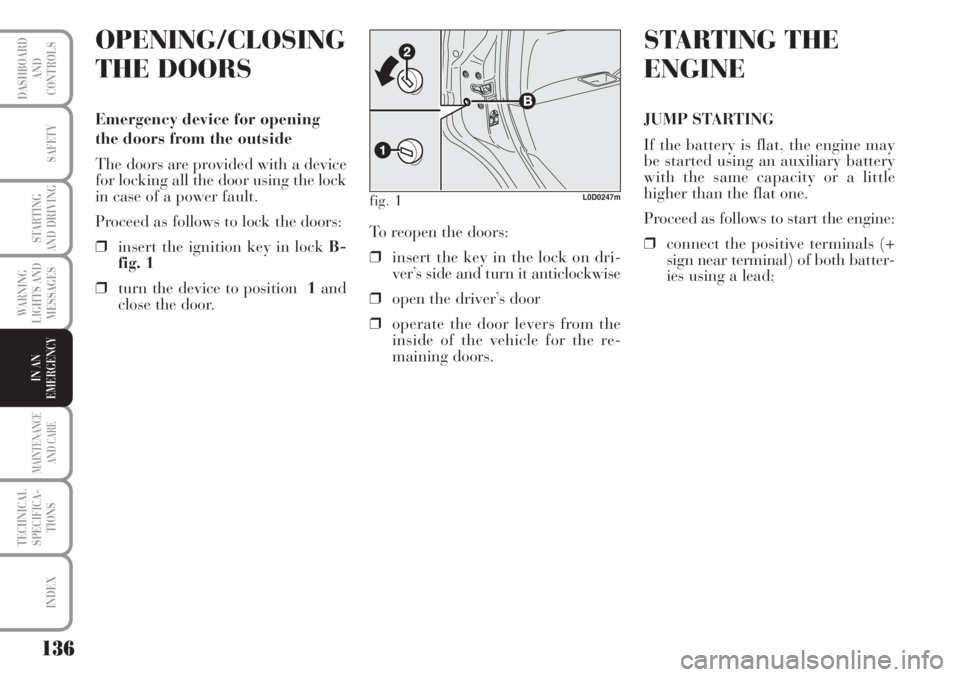
The doors are provided with a device
for locking all the door using the lock
in case of a power fault.
Proceed as follows to lock the doors:
❒insert the ignition key in lock B-
fig. 1
❒turn the device to position 1and
close the door.
fig. 1L0D0247m
STARTING THE
ENGINE
JUMP STARTING
If the battery is flat, the engine may
be started using an auxiliary battery
with the same capacity or a little
higher than the flat one.
Proceed as follows to start the engine:
❒connect the positive terminals (+
sign near terminal) of both batter-
ies using a lead; To reopen the doors:
❒insert the key in the lock on dri-
ver’s side and turn it anticlockwise
❒open the driver’s door
❒operate the door levers from the
inside of the vehicle for the re-
maining doors.
Page 138 of 218
137
WARNING
LIGHTS AND
MESSAGES
MAINTENANCE
AND CARE
TECHNICAL
SPECIFICA-
TIONS
INDEX
DASHBOARD
AND
CONTROLS
SAFETY
STARTING
AND DRIVING
IN AN
EMERGENCY
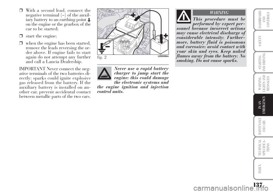
❒With a second lead, connect the
negative terminal (–) of the auxil-
iary battery to an earthing point E
on the engine or the gearbox of the
car to be started;
❒start the engine;
❒when the engine has been started,
remove the leads reversing the or-
der above. If engine fails to start
again do not attempt any further
and call a Lancia Dealership.
IMPORTANT Never connect the neg-
ative terminals of the two batteries di-
rectly: sparks could ignite explosive
gas released from the battery. If the
auxiliary battery is installed on an-
other car, prevent accidental contact
between metallic parts of the two cars.
fig. 2L0D0396m
This procedure must be
performed by expert per-
sonnel because incorrect actions
may cause electrical discharge of
considerable intensity. Further-
more, battery fluid is poisonous
and corrosive: avoid contact with
your skin and eyes. Keep naked
flames away from the battery. No
smoking. Do not cause sparks.
WARNING
Never use a rapid battery
charger to jump start the
engine: this could damage
the electronic systems and
the engine ignition and injection
control units.
Page 158 of 218
157
WARNING
LIGHTS AND
MESSAGES
MAINTENANCE
AND CARE
TECHNICAL
SPECIFICA-
TIONS
INDEX
DASHBOARD
AND
CONTROLS
SAFETY
STARTING
AND DRIVING
IN AN
EMERGENCY
Remove the key from the
ignition switch and switch
off all loads before replacing a
fuse.
WARNING
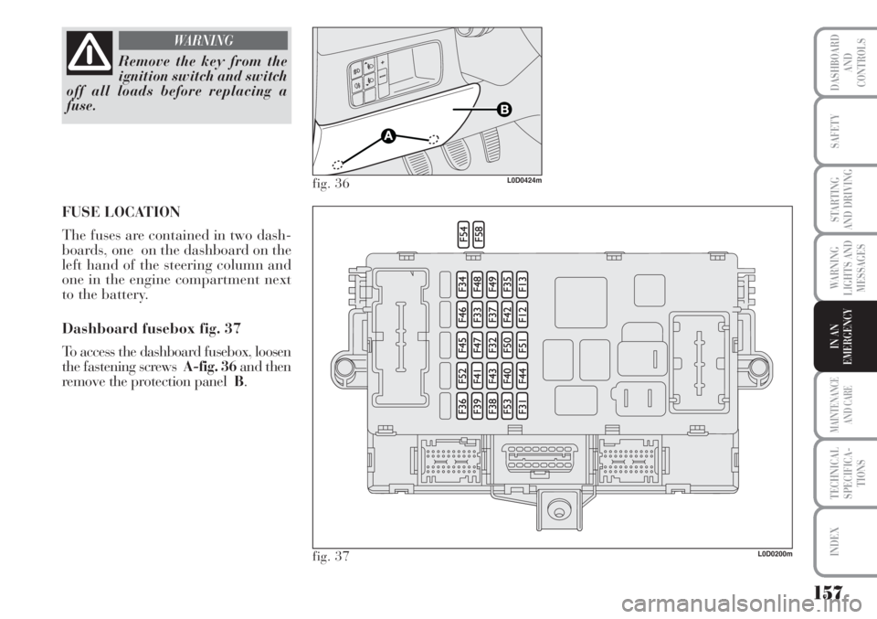
FUSE LOCATION
The fuses are contained in two dash-
boards, one on the dashboard on the
left hand of the steering column and
one in the engine compartment next
to the battery.
Dashboard fusebox fig. 37
To access the dashboard fusebox, loosen
the fastening screws A-fig. 36and then
remove the protection panel B.
L0D0200m
fig. 36L0D0424m
fig. 37
Page 160 of 218
159
WARNING
LIGHTS AND
MESSAGES
MAINTENANCE
AND CARE
TECHNICAL
SPECIFICA-
TIONS
INDEX
DASHBOARD
AND
CONTROLS
SAFETY
STARTING
AND DRIVING
IN AN
EMERGENCY
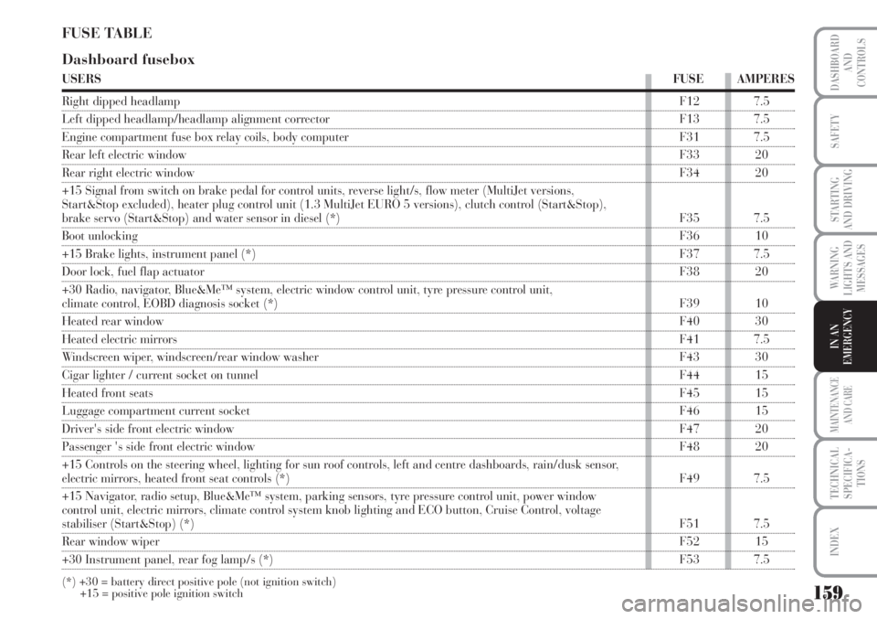
FUSE TABLE
Dashboard fusebox
USERSFUSE AMPERES
Right dipped headlampF12 7.5
Left dipped headlamp/headlamp alignment corrector F13 7.5
Engine compartment fuse box relay coils, body computer F31 7.5
Rear left electric windowF33 20
Rear right electric windowF34 20
+15 Signal from switch on brake pedal for control units, reverse light/s, flow meter (MultiJet versions,
Start&Stop excluded), heater plug control unit (1.3 MultiJet EURO 5 versions), clutch control (Start&Stop),
brake servo (Start&Stop) and water sensor in diesel (*) F35 7.5
Boot unlocking F36 10
+15 Brake lights, instrument panel (*)F37 7.5
Door lock, fuel flap actuatorF38 20
+30 Radio, navigator, Blue&Me™ system, electric window control unit, tyre pressure control unit,
climate control, EOBD diagnosis socket (*)F39 10
Heated rear window F40 30
Heated electric mirrorsF41 7.5
Windscreen wiper, windscreen/rear window washer F43 30
Cigar lighter / current socket on tunnelF44 15
Heated front seatsF45 15
Luggage compartment current socketF46 15
Driver's side front electric windowF47 20
Passenger 's side front electric windowF48 20
+15 Controls on the steering wheel, lighting for sun roof controls, left and centre dashboards, rain/dusk sensor,
electric mirrors, heated front seat controls (*)F49 7.5
+15 Navigator, radio setup, Blue&Me™ system, parking sensors, tyre pressure control unit, power window
control unit, electric mirrors, climate control system knob lighting and ECO button, Cruise Control, voltage
stabiliser (Start&Stop) (*)F51 7.5
Rear window wiperF52 15
+30 Instrument panel, rear fog lamp/s (*)F53 7.5
(*) +30 = battery direct positive pole (not ignition switch)
+15 = positive pole ignition switch
Page 161 of 218
160
WARNING
LIGHTS AND
MESSAGES
MAINTENANCE
AND CARE
TECHNICAL
SPECIFICA-
TIONS
INDEX
DASHBOARD
AND
CONTROLS
SAFETY
STARTING
AND DRIVING
IN AN
EMERGENCY
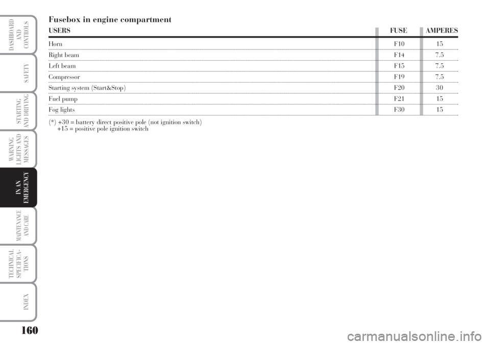
Fusebox in engine compartment
USERSFUSE AMPERES
HornF10 15
Right beamF14 7.5
Left beamF15 7.5
CompressorF19 7.5
Starting system (Start&Stop)F20 30
Fuel pumpF21 15
Fog lightsF30 15
(*) +30 = battery direct positive pole (not ignition switch)
+15 = positive pole ignition switch
Page 162 of 218
161
WARNING
LIGHTS AND
MESSAGES
MAINTENANCE
AND CARE
TECHNICAL
SPECIFICA-
TIONS
INDEX
DASHBOARD
AND
CONTROLS
SAFETY
STARTING
AND DRIVING
IN AN
EMERGENCY
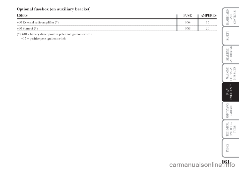
Optional fusebox (on auxiliary bracket)
USERSFUSE AMPERES
+30 External radio amplifier (*)F54 15
+30 Sunroof (*)F58 20
(*) +30 = battery direct positive pole (not ignition switch)
+15 = positive pole ignition switch
Page 180 of 218
179
WARNING
LIGHTS AND
MESSAGES
TECHNICAL
SPECIFICA-
TIONS
INDEX
DASHBOARD
AND
CONTROLS
SAFETY
STARTING
AND DRIVING
IN AN
EMERGENCY
MAINTENANCE
AND CARE
IMPORTANT A battery which is kept
at a charge of less than 50% (optical
indicator with dark colour without
green area in the middle) for any
length of time will be damaged by sul-
phation leading to a reduction in
cranking power.
The battery will also be more at risk
of freezing (e.g. already at -10°C).
In case of prolonged halt, refer to the
“Storing the car” paragraph in the
“Starting and driving” chapter.
If after buying the car, you want to in-
stall electric accessories which require
permanent electric supply (alarm,
etc.) contact Lancia Dealership whose
qualified personnel, in addition to
suggesting the most suitable devices
from Lineaccessori Lancia, will eval-
uate the overall electric absorption,
checking whether the car’s electric
system is capable of withstanding the
load required, or whether it should be
integrated with a more powerful bat-
tery.
Since these devices continue absorb-
ing energy even when the ignition key
is off, they gradually run down the
battery.WHEELS AND
TYRES
Check the pressure of each type, in-
cluding the spare, approximately once
every two weeks and before starting a
long journey: this check must be per-
formed with the tyre rested and cold.
It is normal for pressure to increase
when the car is used. For the correct
tyre inflation pressure, see “Wheels”
in “Technical specifications” section.
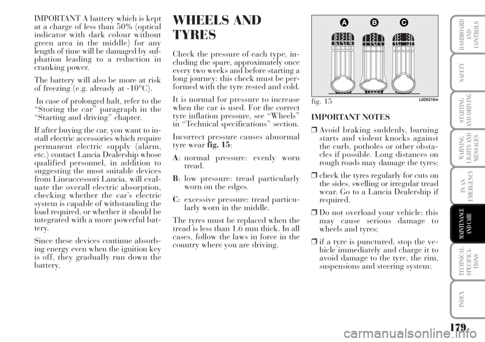
Incorrect pressure causes abnormal
tyre wearfig. 15:
A: normal pressure: evenly worn
tread.
B: low pressure: tread particularly
worn on the edges.
C: excessive pressure: tread particu-
larly worn in the middle.
The tyres must be replaced when the
tread is less than 1.6 mm thick. In all
cases, follow the laws in force in the
country where you are driving.IMPORTANT NOTES
❒Avoid braking suddenly, burning
starts and violent knocks against
the curb, potholes or other obsta-
cles if possible. Long distances on
rough roads may damage the tyres;
❒check the tyres regularly for cuts on
the sides, swelling or irregular tread
wear. Go to a Lancia Dealership if
required.
❒Do not overload your vehicle: this
may cause serious damage to
wheels and tyres;
❒if a tyre is punctured, stop the ve-
hicle immediately and charge it to
avoid damage to the tyre, the rim,
suspensions and steering system;
fig. 15L0D0216m
Page 193 of 218
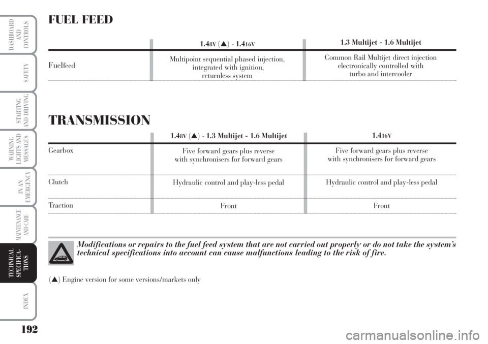
Modifications or repairs to the fuel feed system that are not carried out properly or do not take the system’s
technical specifications into account can cause malfunctions leading to the risk of fire.
(▲) Engine version for some versions/markets only
FUEL FEED
Fuelfeed
1.48V(▲)-1.416V
Multipoint sequential phased injection,
integrated with ignition,
returnless system1.3 Multijet - 1.6 Multijet
Common Rail Multijet direct injection
electronically controlled with
turbo and intercooler
TRANSMISSION
Gearbox
Clutch
Traction1.4
16V
Five forward gears plus reverse
with synchronisers for forward gears
Hydraulic control and play-less pedal
Front 1.4
8V(▲)-1.3 Multijet - 1.6 Multijet
Five forward gears plus reverse
with synchronisers for forward gears
Hydraulic control and play-less pedal
Front
192
WARNING
LIGHTS AND
MESSAGES
INDEX
DASHBOARD
AND
CONTROLS
SAFETY
STARTING
AND DRIVING
IN AN
EMERGENCY
MAINTENANCE
AND CARE
TECHNICAL
SPECIFICA-
TIONS
Page 208 of 218
207
WARNING
LIGHTS AND
MESSAGES
DASHBOARD
AND
CONTROLS
SAFETY
STARTING
AND DRIVING
IN AN
EMERGENCY
MAINTENANCE
AND CARE
TECHNICAL
SPECIFICA-
TIONS
INDEX
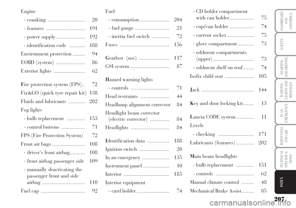
Engine
- cranking ........................... 20
- features ............................ 191
- power supply ..................... 192
- identification code ........... 188
Environment protection ......... 94
EOBD (system) ..................... 86
Exterior lights ....................... 62
Fire protection system (FPS).. 72
Fix&GO (quick tyre repair kit) 138
Fluids and lubricants ............ 202
Fog lights
- bulb replacement ............. 153
- control buttons ................. 71
FPS (Fire Protection System) 72
Front air bags ........................ 108
- driver's front airbag........... 108
- front airbag passenger side 109
- manually deactivating the
passenger front and side
airbag ............................... 110
Fuel cap ................................ 92Fuel
- consumption ...................... 204
- fuel gauge ......................... 21
- inertia fuel switch ............. 72
Fuses .................................... 156
Gearbox (use) ...................... 117
GSI system ............................. 87
Hazard warning lights
- controls ............................ 71
Head restraints ..................... 44
Headlamp alignment corrector 84
Headlight beam corrector
(electric corrector) .............. 84
Headlights ............................ 84
Identification data ................ 188
Ignition switch ...................... 20
In an emergency .................... 135
Instrument panel ................... 10
Interior ................................. 185
Interior equipment
- card holder ........................ 74- CD holder compartment
with can holder.................. 75
- cup/can holder .................. 74
- current socket .................... 75
- glove compartment ............ 73
- oddment compartments
(upper) .............................. 73
- oddment shelf on roof ........ 74
Isofix child seat ..................... 105
Jack ...................................... 144
Key and door locking kit........ 13
Lancia CODE system ............. 11
Levels
- checking .......................... 171
Lubricants (features) ............. 202
Main beam headlights
- bulb replacement ............. 151
- controls ............................ 62
Manual climate control ......... 48
Mechanical Brake Assist ......... 85