lights Lancia Thema 2012 Owner handbook (in English)
[x] Cancel search | Manufacturer: LANCIA, Model Year: 2012, Model line: Thema, Model: Lancia Thema 2012Pages: 316, PDF Size: 3.85 MB
Page 22 of 316
If one of the previously described
arming sequences has occurred, the
Vehicle Security Alarm will arm re-
gardless of whether you are in the
vehicle or not. If you remain in the
vehicle and open a door, the alarm
will sound. If this occurs, disarm the
Vehicle Security Alarm.
If the Vehicle Security Alarm is armed
and the battery becomes discon-
nected, the Vehicle Security Alarm
will remain armed when the battery is
reconnected; the exterior lights will
flash, the horn will sound. If this oc-
curs, disarm the Vehicle Security
Alarm.
ILLUMINATED ENTRY
(for versions/markets,
where provided)
The courtesy lights will turn on when
you use the Remote Keyless Entry
(RKE) transmitter to unlock the
doors or open any door.
This feature also turns on the ap-
proach lighting in the outside mirrors
(for versions/markets, where pro-
vided). Refer to “Mirrors” in “Under-standing The Features Of Your Ve-
hicle” for further information.
The lights will fade to off after ap-
proximately 30 seconds or they will
immediately fade to off once the igni-
tion is cycled to the ON/RUN position
from the OFF position.
NOTE:
The front courtesy overhead
console and door courtesy lights
will turn on if the dimmer con-
trol is in the "Dome ON" position
(extreme top position).
The Illuminated Entry system will not operate if the dimmer
control is in the “Dome defeat”
position (extreme bottom posi-
tion).
REMOTE KEYLESS
ENTRY (RKE)
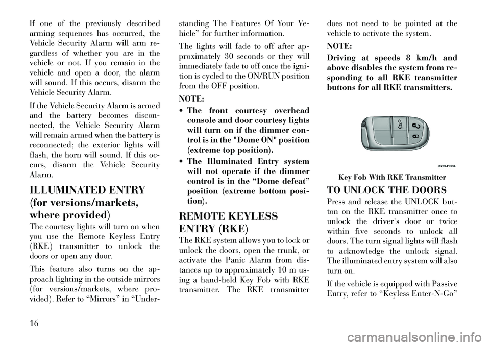
The RKE system allows you to lock or
unlock the doors, open the trunk, or
activate the Panic Alarm from dis-
tances up to approximately 10 m us-
ing a hand-held Key Fob with RKE
transmitter. The RKE transmitter does not need to be pointed at the
vehicle to activate the system.
NOTE:
Driving at speeds 8 km/h and
above disables the system from re-
sponding to all RKE transmitter
buttons for all RKE transmitters.
TO UNLOCK THE DOORS
Press and release the UNLOCK but-
ton on the RKE transmitter once to
unlock the driver's door or twice
within five seconds to unlock all
doors. The turn signal lights will flash
to acknowledge the unlock signal.
The illuminated entry system will also
turn on.
If the vehicle is equipped with Passive
Entry, refer to “Keyless Enter-N-Go”
Key Fob With RKE Transmitter
16
Page 23 of 316
under “Things To Know Before Start-
ing Your Vehicle” for further informa-
tion.
Remote Key Unlock, Driver
Door/All Doors 1st Press
This feature lets you program the sys-
tem to unlock either the driver's door
or all doors on the first press of the
UNLOCK button on the RKE trans-
mitter. To change the current setting,
refer to “Uconnect Touch™ Settings”
in “Understanding Your Instrument
Panel” for further information.
Flash Lights With Lock
This feature will cause the turn signal
lights to flash when the doors are
locked or unlocked with the RKE
transmitter. This feature can be
turned on or turned off. To change the
current setting, refer to “Uconnect
Touch™ Settings” in “Understanding
Your Instrument Panel” for further
information.
Turn Headlights On With Remote
Key Unlock
This feature activates the headlights
for up to 90 seconds when the doors
are unlocked with the RKE transmit-ter. The time for this feature is pro-
grammable on vehicles equipped
through Uconnect Touch™. To
change the current setting, refer to
“Uconnect Touch™ Settings” in “Un-
derstanding Your Instrument Panel”
for further information.
TO LOCK THE DOORS
Press and release the LOCK button on
the RKE transmitter to lock all doors.
The turn signal lights will flash to
acknowledge the signal.
If the vehicle is equipped with Passive
Entry, refer to “Keyless Enter-N-Go”
under “Things To Know Before Start-
ing Your Vehicle” for further informa-
tion.
TO UNLATCH THE TRUNK
Press the TRUNK button on the RKE
transmitter two times within five sec-
onds to unlatch the trunk.
If the vehicle is equipped with Passive
Entry, refer to “Keyless Enter-N-Go”
under “Things To Know Before Start-
ing Your Vehicle” for further informa-
tion.
PROGRAMMING
ADDITIONAL
TRANSMITTERS
Programming Key Fobs or RKE
transmitters may be performed at an
authorized dealer.
TRANSMITTER BATTERY
REPLACEMENT
The recommended replacement bat-
tery is one CR2032 battery.
NOTE:
Perchlorate Material — special
handling may apply. Batteries
could contain dangerous mate-
rials. Please dispose of them ac-
cording to respect for environ-
ment and local laws.
Do not touch the battery termi- nals that are on the back hous-
ing or the printed circuit board.
1. Remove the emergency key by
sliding the mechanical latch on the
back of the RKE transmitter sideways
with your thumb and then pull the
key out with your other hand.
2. Insert the tip of the emergency key
or a #2 flat blade screwdriver into the
17
Page 41 of 316
WARNING!(Continued)
Do not put anything on or around
the air bag covers or attempt to
open them manually. You may
damage the air bags and you
could be injured because the air
bags may no longer be functional.
The protective covers for the air
bag cushions are designed to open
only when the air bags are inflat-
ing.
Do not drill, cut or tamper with
the knee bolster (for versions/
markets, where provided) in any
way.
Do not mount any accessories to
the knee bolster (for versions/
markets, where provided) such as
alarm lights, stereos, citizen band
radios, etc.
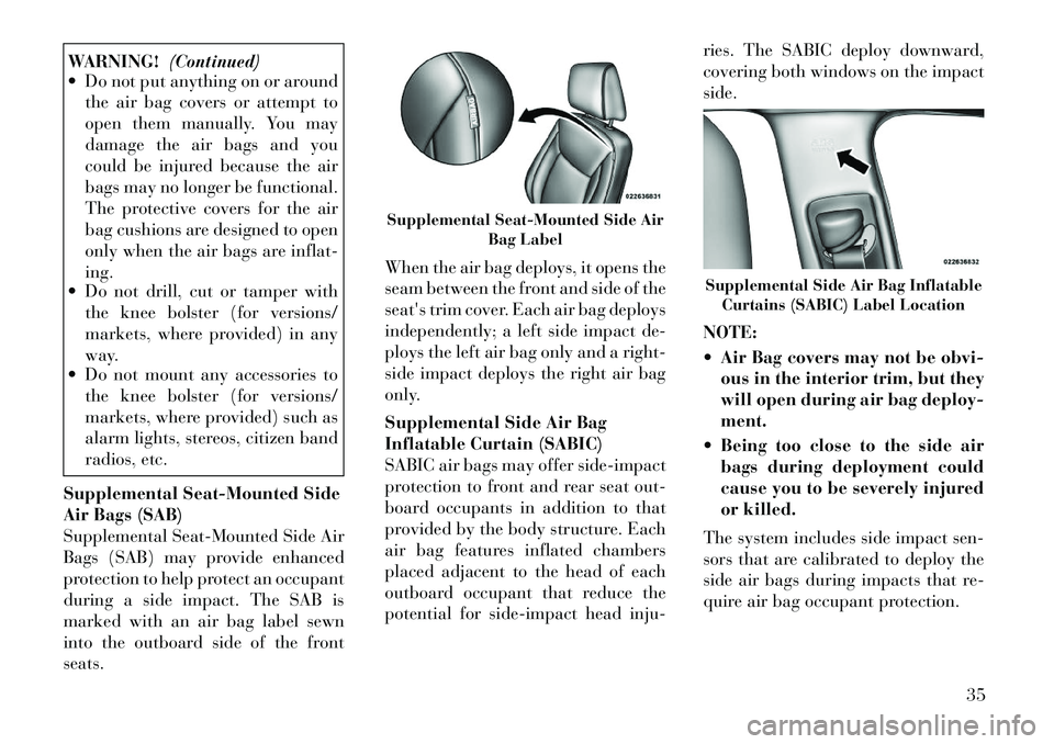
Supplemental Seat-Mounted Side
Air Bags (SAB)
Supplemental Seat-Mounted Side Air
Bags (SAB) may provide enhanced
protection to help protect an occupant
during a side impact. The SAB is
marked with an air bag label sewn
into the outboard side of the front
seats. When the air bag deploys, it opens the
seam between the front and side of the
seat's trim cover. Each air bag deploys
independently; a left side impact de-
ploys the left air bag only and a right-
side impact deploys the right air bag
only.
Supplemental Side Air Bag
Inflatable Curtain (SABIC)
SABIC air bags may offer side-impact
protection to front and rear seat out-
board occupants in addition to that
provided by the body structure. Each
air bag features inflated chambers
placed adjacent to the head of each
outboard occupant that reduce the
potential for side-impact head inju-ries. The SABIC deploy downward,
covering both windows on the impact
side.
NOTE:
Air Bag covers may not be obvi-
ous in the interior trim, but they
will open during air bag deploy-
ment.
Being too close to the side air bags during deployment could
cause you to be severely injured
or killed.
The system includes side impact sen-
sors that are calibrated to deploy the
side air bags during impacts that re-
quire air bag occupant protection.
Supplemental Seat-Mounted Side Air Bag Label
Supplemental Side Air Bag InflatableCurtains (SABIC) Label Location
35
Page 45 of 316
Driver Side Knee Air Bag gas is vented
through small vent holes in the side of
the air bag.
Supplemental Seat-Mounted Side
Air Bag (SAB) Inflator Units
The Supplemental Seat-Mounted
Side Air Bags (SAB) are designed to
activate only in certain side collisions.
The ORC determines if a side collision
requires the side air bags to inflate,
based on several factors, including the
severity and type of collision.
Based on several factors, including
the severity and type of collision, the
side air bag inflator on the crash side
of the vehicle may be triggered, re-
leasing a quantity of non-toxic gas.
The inflating SAB exits through the
seat seam into the space between the
occupant and the door. The SAB fully
inflate in about 10 milliseconds. The
side air bag moves at a very high
speed and with such a high force that
it could injure you if you are not
seated properly, or if items are posi-
tioned in the area where the side air
bag inflates. This especially applies to
children.Supplemental Side Air Bag
Inflatable Curtain (SABIC)
Inflator Units
During collisions where the impact is
confined to a particular area of the
side of the vehicle, the ORC may de-
ploy the SABIC air bags, depending
on the severity and type of collision. In
these events, the ORC will deploy the
SABIC only on the impact side of the
vehicle.
A quantity of non-toxic gas is gener-
ated to inflate the side curtain air bag.
The inflating side curtain air bag
pushes the outside edge of the head-
liner out of the way and covers the
window. The air bag inflates in about
30 milliseconds (about one-quarter of
the time that it takes to blink your
eyes) with enough force to injure you
if you are not belted and seated prop-
erly, or if items are positioned in the
area where the side curtain air bag
inflates. This especially applies to
children. The side curtain air bag is
only about 9 cm thick when it is in-
flated.
Because air bag sensors estimate de-
celeration over time, vehicle speedand damage are not good indicators of
whether or not an air bag should have
deployed.
Front And Side Impact Sensors
In front and side impacts, impact sen-
sors can aid the ORC in determining
appropriate response to impact events.Enhanced Accident Response
System
In the event of an impact causing air
bag deployment, if the communica-
tion network remains intact, and the
power remains intact, depending on
the nature of the event the ORC will
determine whether to have the En-
hanced Accident Response System
perform the following functions:
Cut off fuel to the engine.
Flash hazard lights as long as the
battery has power or until the igni-
tion key is turned off.
Turn on the interior lights, which remain on as long as the battery has
power, until the ignition key is re-
moved or the ignition switch is
changed to OFF using the Keyless
Go Start/Stop button.
Unlock the doors automatically.
39
Page 59 of 316

Periodic Safety Checks You
Should Make Outside The
Vehicle
Tires
Examine tires for excessive tread wear
and uneven wear patterns. Check for
stones, nails, glass, or other objects
lodged in the tread or sidewall. In-
spect the tread for cuts and cracks.
Inspect sidewalls for cuts, cracks and
bulges. Check the wheel nuts fortightness. Check the tires (including
spare) for proper cold inflation pres-
sure.
Lights
Have someone observe the operation
of exterior lights while you work the
controls. Check turn signal and high
beam indicator lights on the instru-
ment panel.
Door Latches
Check for positive closing, latching,
and locking.Fluid Leaks
Check area under vehicle after over-
night parking for fuel, engine coolant,
oil, or other fluid leaks. Also, if gaso-
line fumes are detected or if fuel,
power steering fluid, or brake fluid
leaks are suspected, the cause should
be located and corrected immediately.
53
Page 63 of 316

HEAD RESTRAINTS . . . . . . . . . . . . . . . . . . . . 99
FOLDING REAR SEAT . . . . . . . . . . . . . . . . . . 101
DRIVER MEMORY SEAT (for versions/ markets, where provided) . . . . . . . . . . . . . . . . . 101
PROGRAMMING THE MEMORY FEATURE . . 102
LINKING AND UNLINKING THE REMOTE KEYLESS ENTRY TRANSMITTER TO
MEMORY . . . . . . . . . . . . . . . . . . . . . . . . . . . . 102
MEMORY POSITION RECALL . . . . . . . . . . . . 103
EASY ENTRY/EXIT SEAT (Available With Memory Seat Only) . . . . . . . . . . . . . . . . . . . . . 103
TO OPEN AND CLOSE THE HOOD . . . . . . . . . . 104
LIGHTS . . . . . . . . . . . . . . . . . . . . . . . . . . . . . . . 104 HEADLIGHT SWITCH . . . . . . . . . . . . . . . . . . 104
AUTOMATIC HEADLIGHTS . . . . . . . . . . . . . . 105
HEADLIGHTS ON WITH WIPERS(Available With Automatic Headlights Only)
. . 105
HEADLIGHT TIME DELAY . . . . . . . . . . . . . . 105
SMARTBEAM™ . . . . . . . . . . . . . . . . . . . . . . . 106
DAYTIME RUNNING LIGHTS (DRLs) . . . . . . 106
ADAPTIVE BI-XENON HIGH INTENSITY DISCHARGE HEADLIGHTS (for
versions/markets, where provided) . . . . . . . . 106
LIGHTS-ON REMINDER . . . . . . . . . . . . . . . . 107
FOG LIGHTS . . . . . . . . . . . . . . . . . . . . . . . . . 107
MULTIFUNCTION LEVER . . . . . . . . . . . . . . . 107
57
Page 64 of 316
TURN SIGNALS . . . . . . . . . . . . . . . . . . . . . . . 107
LANE CHANGE ASSIST . . . . . . . . . . . . . . . . . 107
HIGH/LOW BEAM SWITCH . . . . . . . . . . . . . . 107
FLASH-TO-PASS . . . . . . . . . . . . . . . . . . . . . . 108
COURTESY LIGHTS . . . . . . . . . . . . . . . . . . . 108
FRONT MAP/READING LIGHTS . . . . . . . . . . 108
AMBIENT LIGHT . . . . . . . . . . . . . . . . . . . . . . 108
INTERIOR LIGHTS . . . . . . . . . . . . . . . . . . . . 108
WINDSHIELD WIPERS AND WASHERS . . . . . . 110 INTERMITTENT WIPER SYSTEM . . . . . . . . . 110
MIST FEATURE . . . . . . . . . . . . . . . . . . . . . . . 110
WINDSHIELD WASHERS . . . . . . . . . . . . . . . 111
HEADLIGHTS ON WITH WIPERS(Available With Automatic Headlights Only)
. . 111
RAIN SENSING WIPERS (for versions/ markets, where provided) . . . . . . . . . . . . . . . 111
HEADLIGHT WASHERS (for versions/markets, where provided) . . . . . . . . . . . . . . . . . . . . . . . . . 112
TILT/TELESCOPING STEERING COLUMN . . . . 112
POWER TILT/TELESCOPING STEERING COLUMN (for versions/markets, where
provided) . . . . . . . . . . . . . . . . . . . . . . . . . . . . . . 113
HEATED STEERING WHEEL (for versions/markets, where provided) . . . . . . . . . . 114
ADJUSTABLE PEDALS (for versions/markets, where provided) . . . . . . . . . . . . . . . . . . . . . . . . . 114
58
Page 66 of 316
PRECAUTIONS WHILE DRIVING WITHACC . . . . . . . . . . . . . . . . . . . . . . . . . . . . . . . . 125
NORMAL (FIXED SPEED) CRUISE CONTROL MODE . . . . . . . . . . . . . . . . . . . . . . 126
FORWARD COLLISION WARNING (for versions/markets, where provided) . . . . . . . . 128
PARKSENSE® PARK ASSIST . . . . . . . . . . . . . . 129 PARKSENSE® SENSORS . . . . . . . . . . . . . . . . 129
PARKSENSE® WARNING DISPLAY . . . . . . . . 129
PARKSENSE® DISPLAY . . . . . . . . . . . . . . . . 130
FRONT PARK ASSIST AUDIBLE ALERTS . . . 131
ENABLING AND DISABLING PARKSENSE®
. . . 131
SERVICE THE PARKSENSE® PARK ASSIST SYSTEM . . . . . . . . . . . . . . . . . . . . . . . . . . . . 131
CLEANING THE PARKSENSE® SYSTEM . . . 132
PARKSENSE® SYSTEM USAGE PRECAUTIONS . . . . . . . . . . . . . . . . . . . . . . . 132
PARKVIEW® REAR BACK UP CAMERA (for versions/markets, where provided) . . . . . . . . . . 134
TURNING PARKVIEW® ON OR OFF — WITH TOUCH SCREEN RADIO . . . . . . . . . . . 135
OVERHEAD CONSOLE . . . . . . . . . . . . . . . . . . . 135 FRONT MAP/READING LIGHTS . . . . . . . . . . 135
SUNGLASS BIN DOOR . . . . . . . . . . . . . . . . . . 135
POWER SUNROOF (for versions/markets, where provided) . . . . . . . . . . . . . . . . . . . . . . . . . 136
60
Page 70 of 316

Three of the LEDs are turn signal
indicators, which flash with the corre-
sponding turn signal lights in the
front and rear of the vehicle. Turning
on the Hazard Warning flashers will
also activate these LEDs.
The other two LEDs supply illumi-
nated entry lighting, which turns on
in both mirrors when you use the Re-
mote Keyless Entry (RKE) transmit-
ter or open any door. These LEDs
shine outward to illuminate the front
and rear door handles. They also
shine downward to illuminate the
area in front of the doors.
The Illuminated Entry lighting fades
to off after about 30 seconds or it will
fade to off immediately once the igni-
tion is placed into the RUN position.
NOTE:
The approach lighting will not
function when the shift lever is
moved out of the PARK position.TILT MIRRORS IN
REVERSE (for
versions/markets, where
provided)
Tilt Mirrors in Reverse provides auto-
matic outside mirror positioning
which will aid the driver’s view of the
ground rearward of the front doors.
The outside mirrors will move slightly
downward from the present position
when the vehicle is shifted into RE-
VERSE. The outside mirrors will then
return to the original position when
the vehicle is shifted out of the RE-
VERSE position. Each stored
memory setting will have an associ-
ated Tilt Mirrors in Reverse position.
NOTE:
The Tilt Mirrors in Reverse feature
can be turned on and off using the
Uconnect Touch™ System, refer to
“Uconnect Touch™ Settings” in
“Understanding Your Instrument
Panel” for further information.POWER MIRRORS
The power mirror controls are located
on the driver's door trim panel.
The power mirror controls consist of
mirror select buttons and a four-way
mirror control switch. To adjust a mir-
ror, press either the L (left) or R
(right) button to select the mirror that
you want to adjust.
NOTE:
A light in the select button will
illuminate indicating the mirror is
activated and can be adjusted.
Using the mirror control switch, press
on any of the four arrows for the di-
rection that you want the mirror to
move.
Power Mirror Control
64
Page 75 of 316
WARNING!
RCP is not a Back Up Aid system. It
is intended to be used to help a
driver detect an oncoming vehicle in
a parking lot situation. Drivers must
be careful when backing up, even
when using RCP. Always check care-
fully behind your vehicle, look be-
hind you, and be sure to check for
pedestrians, animals, other vehicles,
obstructions, and blind spots before
backing up. Failure to do so can
result in serious injury or death.
MODES OF OPERATION
Three selectable modes of operation
are available in the Uconnect Touch™
System. Refer to “Uconnect Touch™
Settings” in “Understanding Your In-
strument Panel” for further informa-
tion. Blind Spot Alert
When operating in Blind Spot Alert
mode, the BSM system will provide a
visual alert in the appropriate side
view mirror based on a detected ob-
ject. However, when the system is op-
erating in RCP, the system will re-
spond with both visual and audible
alerts when a detected object is pres-
ent. Whenever an audible alert is re-
quested, the radio volume is reduced.
Blind Spot Alert Lights/Chime
When operating in Blind Spot Alert
Lights/Chime mode, the BSM system
will provide a visual alert in the ap-
propriate side view mirror based on a
detected object. If the turn signal is
then activated, and it corresponds to
an alert present on that side of the
vehicle, an audible chime will also be
sounded. Whenever a turn signal and
detected object are present on the
same side at the same time, both the
visual and audio alerts will be issued.
In addition to the audible alert, the
radio (if on) volume will be reduced.NOTE:
Whenever an audible alert is re-
quested by the BSM system, the
radio volume is reduced.
If the hazard flashers are on, the system will request the appro-
priate visual alert only.
When the system is in RCP, the
system shall respond with both vi-
sual and audible alerts when a de-
tected object is present. Whenever
an audible alert is requested, the
radio is also muted. Turn/hazard
signal status is ignored; the RCP
state always requests the audible
chime.
Blind Spot Alert Off
When the BSM system is turned off,
there will be no visual or audible
alerts from either the BSM or RCP
systems.
NOTE:
The BSM system will store the cur-
rent operating mode when the ve-
hicle is shut off. Each time the ve-
hicle is started, the previously
stored mode will be recalled and
used.
69