ignition Lancia Thema 2013 Owner handbook (in English)
[x] Cancel search | Manufacturer: LANCIA, Model Year: 2013, Model line: Thema, Model: Lancia Thema 2013Pages: 336, PDF Size: 3.87 MB
Page 70 of 336
ENABLING AND DISABLING PARKSENSE® . . .136SERVICE THE PARKSENSE® PARK ASSIST
SYSTEM . . . . . . . . . . . . . . . . . . . . . . . . . . . . . .136 CLEANING THE PARKSENSE® SYSTEM . . . . .137
PARKSENSE® SYSTEM USAGEPRECAUTIONS. . . . . . . . . . . . . . . . . . . . . . . . .137
PARKVIEW® REAR BACK UP CAMERA (for versions/markets, where provided) . . . . . . . .138
TURNING PARKVIEW® ON OR OFF — WITH TOUCH SCREEN . . . . . . . . . . . . . . . . . .140
OVERHEAD CONSOLE . . . . . . . . . . . . . . . . . . . .140
SUNGLASS BIN DOOR . . . . . . . . . . . . . . . . . .140
POWER SUNROOF (for versions/markets, where provided) . . . . . . . .140
OPENING SUNROOF — EXPRESS . . . . . . . . . .143
OPENING SUNROOF — MANUAL MODE . . . . .143
CLOSING SUNROOF — EXPRESS . . . . . . . . . .143
CLOSING SUNROOF — MANUAL MODE . . . . .143
PINCH PROTECT FEATURE. . . . . . . . . . . . . . .144
VENTING SUNROOF — EXPRESS . . . . . . . . . .141
SUNSHADE OPERATION . . . . . . . . . . . . . . . . .142
WIND BUFFETING . . . . . . . . . . . . . . . . . . . . .142
SUNROOF MAINTENANCE . . . . . . . . . . . . . . .142
IGNITION OFF OPERATION . . . . . . . . . . . . . . .144
64
Page 71 of 336
COMMANDVIEW® SUNROOF WITHPOWER SHADE — (for versions/markets,
where provided) . . . . . . . . . . . . . . . . . . . . . . . . .142
OPENING SUNROOF — EXPRESS . . . . . . . . . .143
OPENING SUNROOF — MANUAL MODE . . . . .143
CLOSING SUNROOF — EXPRESS . . . . . . . . . .143
CLOSING SUNROOF — MANUAL MODE . . . . .143
OPENING POWER SHADE — EXPRESS . . . . .143
OPENING POWER SHADE — MANUAL MODE . . . . . . . . . . . . . . . . . . . . . . . .144
CLOSING POWER SHADE — EXPRESS. . . . . .144
CLOSING POWER SHADE — MANUAL MODE . . . . . . . . . . . . . . . . . . . . . . . .144
PINCH PROTECT FEATURE. . . . . . . . . . . . . . .144
WIND BUFFETING . . . . . . . . . . . . . . . . . . . . .144
SUNROOF MAINTENANCE . . . . . . . . . . . . . . . .144
IGNITION OFF OPERATION . . . . . . . . . . . . . . .144
SUNROOF FULLY CLOSED . . . . . . . . . . . . . . .145
ELECTRICAL POWER OUTLETS . . . . . . . . . . . .145
CUPHOLDERS . . . . . . . . . . . . . . . . . . . . . . . . . .147
FRONT SEAT CUPHOLDERS . . . . . . . . . . . . . .147
REAR SEAT CUPHOLDERS . . . . . . . . . . . . . . .148
STORAGE . . . . . . . . . . . . . . . . . . . . . . . . . . . . . . .148
GLOVEBOX STORAGE . . . . . . . . . . . . . . . . . . .148
CONSOLE FEATURES . . . . . . . . . . . . . . . . . . .148
65
Page 90 of 336
the far end, a call on hold may not
become active automatically. This is
cell phone-dependent.
Redial
Press the “Redial” soft-key,
or press the
and after the “Lis-
tening” prompt and the following
beep, say “Redial”,
After the “Listening” prompt and the following beep, say “Redial”,
The Uconnect™ Phone will call the last number that was dialed from
your mobile phone.
Call Continuation
Call continuation is the progression of
a phone call on the Uconnect™ Phone
after the vehicle ignition key has been
switched to OFF.
NOTE: The call will remain
within the vehicle audio system
until the phone becomes out of
range for the Bluetooth® connec-
tion. It is recommended to press
the “transfer” soft-key when leav-
ing the vehicle. UCONNECT™ PHONE
FEATURES
Emergency Assistance
If you are in an emergency and the
mobile phone is reachable:
Pick up the phone and manually
dial the emergency number for
your area.
If the phone is not reachable and the
Uconnect™ Phone is operational, you
may reach the emergency number as
follows:
Press the
button to begin.
After the “Listening” prompt and the following beep, say “Call Emer-
gency or Dial Emergency” and the
Uconnect™ Phone will instruct the
paired mobile phone to call the
emergency number. This feature is
supported in the U.S., Canada, and
Mexico.
NOTE:
The Emergency call may also be initiated by using the touch-
screen. The emergency number dialed is
based on the country where the
vehicle is purchased. The num-
ber dialed may not be appli-
cable with the available mobile
service and area.
The Uconnect™ Phone does slightly lower your chances of
successfully making a phone
call as to that for the mobile
phone directly.
WARNING!
Your phone must be turned on and
connected to the Uconnect™ Phone
to allow use of this vehicle feature
in emergency situations, when the
mobile phone has network coverage
and stays connected to the
Uconnect™ Phone.
Towing Assistance
If you need towing assistance:
Press the
button to begin.
After the “Listening” prompt and the following beep, say “Towing
Assistance”.
84
Page 95 of 336
If multiple numbers are availablefor the contact select which number
you would like to have the message
sent,
Press “Send” or “Cancel”.
Send Messages Using Voice
Commands:
Press the
button,
After the “Listening” prompt and
the following beep, say “Send mes-
sage to John Smith mobile”,After the system prompts you for
what message you want to send, say
the message you wish to send or say
“List”. There are 18 preset messages.While the list of defined messages are
being read, you can interrupt the sys-
tem by pressing the
button and
saying the message you want to send.
After the system confirms that you
want to send your message to John
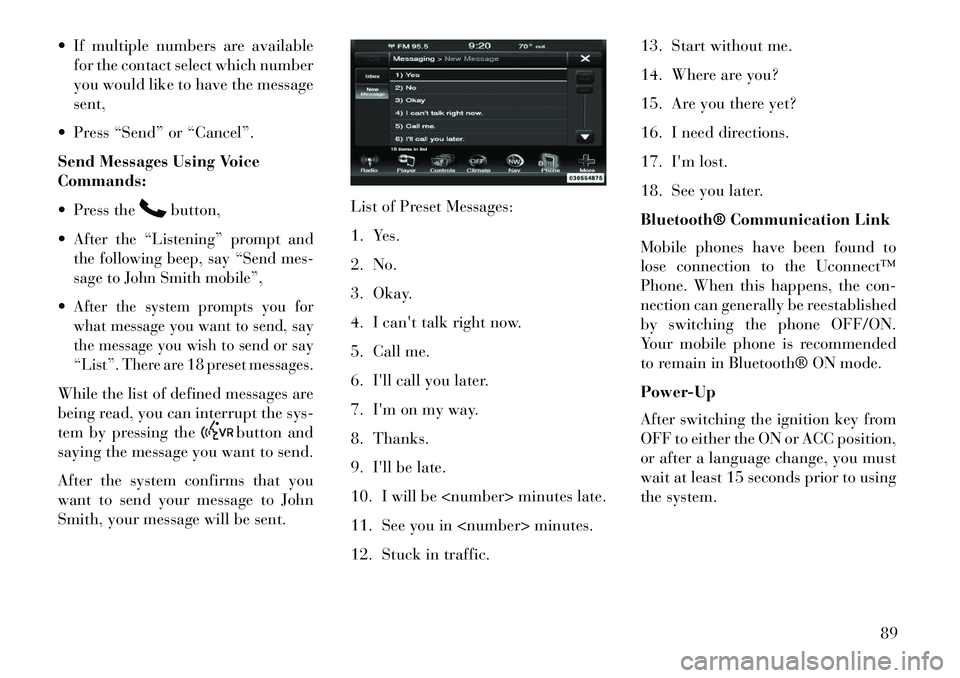
Smith, your message will be sent. List of Preset Messages:
1. Yes.
2. No.
3. Okay.
4. I can't talk right now.
5. Call me.
6. I'll call you later.
7. I'm on my way.
8. Thanks.
9. I'll be late.
10. I will be
11. See you in
12. Stuck in traffic.13. Start without me.
14. Where are you?
15. Are you there yet?
16. I need directions.
17. I'm lost.
18. See you later.
Bluetooth® Communication Link
Mobile phones have been found to
lose connection to the Uconnect™
Phone. When this happens, the con-
nection can generally be reestablished
by switching the phone OFF/ON.
Your mobile phone is recommended
to remain in Bluetooth® ON mode.
Power-Up
After switching the ignition key from
OFF to either the ON or ACC position,
or after a language change, you must
wait at least 15 seconds prior to using
the system.
89
Page 112 of 336
desired position settings for the driver
seat, side mirrors, adjustable pedals
(for versions/markets, where pro-
vided), and power tilt and telescopic
steering column (for versions/
markets, where provided) and a set of
desired radio station presets. Your Re-
mote Keyless Entry (RKE) transmit-
ter can also be programmed to recall
the same positions when the UN-
LOCK button is pressed.
NOTE:
Only one RKE transmitter canbe linked to each of the memory
positions.
Passive Entry door handles can- not be linked to the memory
function. Use either the memory
recall switch or the RKE trans-
mitter (if linked to the memory
feature) to recall memory posi-
tions 1 or 2.
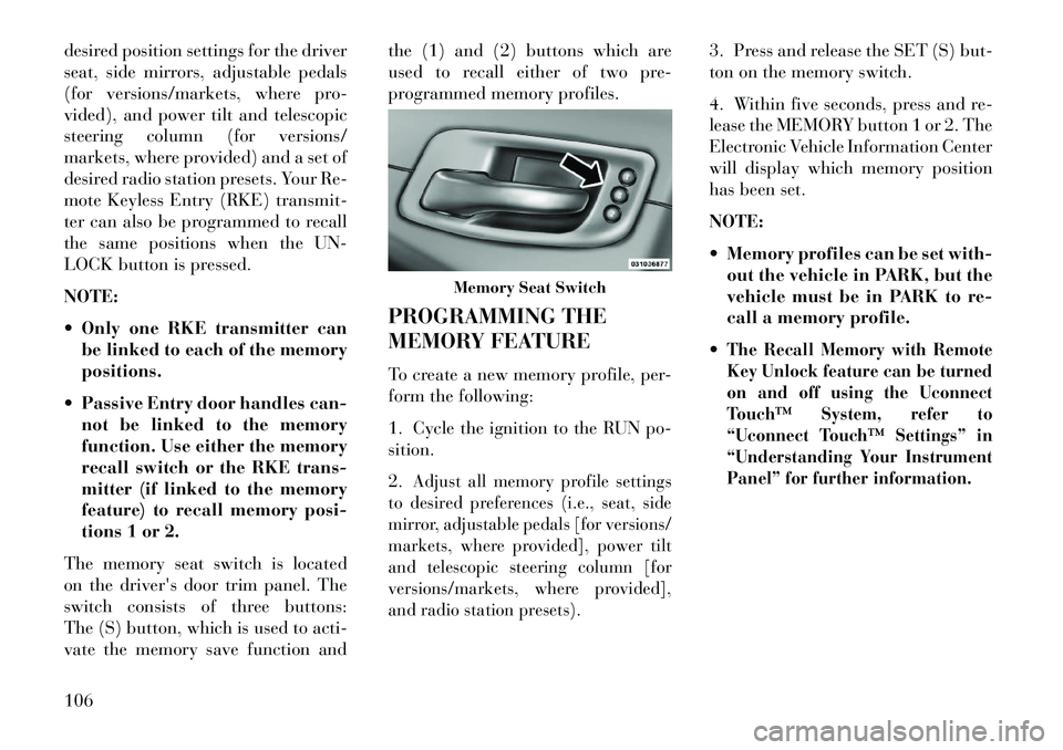
The memory seat switch is located
on the driver's door trim panel. The
switch consists of three buttons:
The (S) button, which is used to acti-
vate the memory save function and the (1) and (2) buttons which are
used to recall either of two pre-
programmed memory profiles.
PROGRAMMING THE
MEMORY FEATURE
To create a new memory profile, per-
form the following:
1. Cycle the ignition to the RUN po-
sition.
2.
Adjust all memory profile settings
to desired preferences (i.e., seat, side
mirror, adjustable pedals [for versions/
markets, where provided], power tilt
and telescopic steering column [for
versions/markets, where provided],
and radio station presets).
3. Press and release the SET (S) but-
ton on the memory switch.
4. Within five seconds, press and re-
lease the MEMORY button 1 or 2. The
Electronic Vehicle Information Center
will display which memory position
has been set.
NOTE:
Memory profiles can be set with- out the vehicle in PARK, but the
vehicle must be in PARK to re-
call a memory profile.
The Recall Memory with Remote
Key Unlock feature can be turned
on and off using the Uconnect
Touch™ System, refer to
“Uconnect Touch™ Settings” in
“Understanding Your Instrument
Panel” for further information.
Memory Seat Switch
106
Page 113 of 336
LINKING AND UNLINKING
THE REMOTE KEYLESS
ENTRY TRANSMITTER TO
MEMORY
Your RKE transmitters can be pro-
grammed to recall one of two pre-
programmed memory profiles by
pressing the UNLOCK button on the
RKE transmitter.
To program your RKE transmitters,
perform the following:
1. Cycle the ignition to the OFF posi-
tion.
2. Select desired memory profile (1)
or (2).
3. Once the profile has been recalled,
press and release the SET (S) button
on the memory switch, then press and
release button (1) or (2) accordingly.
“Memory Profile Set” (1 or 2) will
display in the instrument cluster on
vehicles equipped with the EVIC.
4. Press and release the LOCK but-
ton on the RKE transmitter within
10 seconds.NOTE: Your RKE transmitters
can be unlinked to your memory
settings by pressing the SET (S)
button followed by the UNLOCK
button on the RKE transmitter in
Step 4 above.
MEMORY POSITION
RECALL
NOTE: The vehicle must be in
PARK to recall memory positions.
If a recall is attempted when the
vehicle is not in PARK, a message
will display in the EVIC.
To recall the memory settings for
driver, press MEMORY button num-
ber (1) on the driver's door or the
UNLOCK button on the RKE trans-
mitter linked to memory position 1.
To recall the memory setting for
driver, press MEMORY button num-
ber (2) on the driver's door or the
UNLOCK button on the RKE trans-
mitter linked to memory position 2.
A recall can be cancelled by pressing
any of the MEMORY buttons (S, 1,
or 2) on the driver's door during a
recall. When a recall is cancelled, thedriver seat, side mirror, adjustable
pedals (for versions/markets, where
provided), and power tilt and tele-
scopic steering column (for versions/
markets, where provided) stop mov-
ing. A delay of one second will occur
before another recall can be selected.
EASY ENTRY/EXIT SEAT
(Available With Memory
Seat Only)
This feature provides automatic
driver seat positioning to enhance
driver mobility when entering and
exiting the vehicle.
The distance the driver seat moves
depends on where you have the driver
seat positioned when you place the
ignition to the OFF position.
When you cycle the ignition to the
OFF position, the driver seat will
move about 60 mm rearward if the
driver seat position is greater than
or equal to 68 mm forward of the
rear stop. The seat will return to its
previously set position when you
place the ignition into the ACC or
RUN position.
107
Page 114 of 336
When you cycle the ignition to theOFF position, the driver seat will
move to a position 8 mm forward of
the rear stop if the driver seat posi-
tion is between 23 mm and 68 mm
forward of the rear stop. The seat
will return to its previously set po-
sition when you place the ignition
to the ACC or RUN position.
The Easy Entry/Easy Exit feature is
disabled when the driver seat posi-
tion is less than 23 mm forward of
the rear stop. At this position, there
is no benefit to the driver by moving
the seat for Easy Exit or Easy Entry.Each stored memory setting will have
an associated Easy Entry and Easy
Exit position.
NOTE: The Easy Entry/Easy Exit
feature can be enabled or disabled
using the Uconnect Touch™ Sys-
tem, refer to “Uconnect Touch™
Settings” in “Understanding Your
Instrument Panel” for further in-
formation. TO OPEN AND CLOSE
THE HOOD
Two latches must be released to open
the hood.
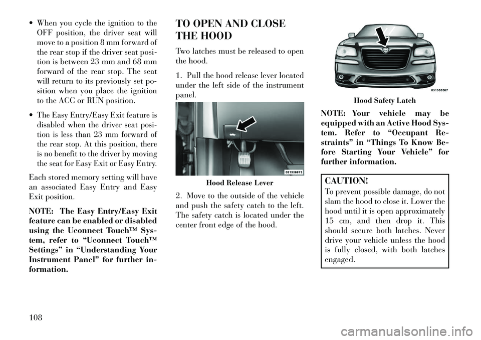
1. Pull the hood release lever located
under the left side of the instrument
panel.
2. Move to the outside of the vehicle
and push the safety catch to the left.
The safety catch is located under the
center front edge of the hood.
NOTE: Your vehicle may be
equipped with an Active Hood Sys-
tem. Refer to “Occupant Re-
straints” in “Things To Know Be-
fore Starting Your Vehicle” for
further information.
CAUTION!
To prevent possible damage, do not
slam the hood to close it. Lower the
hood until it is open approximately
15 cm, and then drop it. This
should secure both latches. Never
drive your vehicle unless the hood
is fully closed, with both latches
engaged.
Hood Release Lever
Hood Safety Latch
108
Page 115 of 336
WARNING!
Be sure the hood is fully latched
before driving your vehicle. If the
hood is not fully latched, it could
open when the vehicle is in motion
and block your vision. Failure to
follow this warning could result in
serious injury or death.
LIGHTS
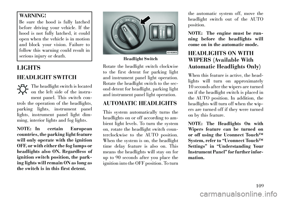
HEADLIGHT SWITCH The headlight switch is located
on the left side of the instru-
ment panel. This switch con-
trols the operation of the headlights,
parking lights, instrument panel
lights, instrument panel light dim-
ming, interior lights and fog lights.
NOTE: In certain European
countries, the parking light feature
will only operate with the ignition
OFF, or with either the fog lamps or
headlights also ON. Regardless of
ignition switch position, the park-
ing lights will remain ON as long as
the switch is in this first detent.
Rotate the headlight switch clockwise
to the first detent for parking light
and instrument panel light operation.
Rotate the headlight switch to the sec-
ond detent for headlight, parking light
and instrument panel light operation.AUTOMATIC HEADLIGHTS
This system automatically turns the
headlights on or off according to am-
bient light levels. To turn the system
on, rotate the headlight switch coun-
terclockwise to the AUTO position.
When the system is on, the headlight
time delay feature is also on. This
means the headlights will stay on for
up to 90 seconds after you place the
ignition into the OFF position. To turn the automatic system off, move the
headlight switch out of the AUTO
position.
NOTE: The engine must be run-
ning before the headlights will
come on in the automatic mode.
HEADLIGHTS ON WITH
WIPERS (Available With
Automatic Headlights Only)
When this feature is active, the head-
lights will turn on approximately
10 seconds after the wipers are turned
on if the headlight switch is placed in
the AUTO position. In addition, the
headlights will turn off when the wip-
ers are turned off if they were turned
on by this feature.
NOTE:
The Headlights On with
Wipers feature can be turned on
or off using the Uconnect Touch™
System, refer to “Uconnect Touch™
Settings” in “Understanding Your
Instrument Panel” for further infor-
mation.
Headlight Switch
109
Page 116 of 336
HEADLIGHT TIME DELAYThis feature provides the safety of
headlight illumination for up to 90 sec-
onds (programmable) when leaving
your vehicle in an unlit area.To activate the delay feature, place
the ignition in the OFF position while
the headlights are still on. Then, turn
off the headlights within 45 seconds.
The delay interval begins when the
headlight switch is turned off.If you turn the headlights or parking
lights on, or place the ignition in ACC
or RUN, the system will cancel the
delay.If you turn the headlights off before
the ignition, they will turn off in the
normal manner.
NOTE:
The lights must be turned offwithin 45 seconds of placing the
ignition in the OFF position to
activate this feature.
The headlight delay time is pro-
grammable using the Uconnect
Touch™ System, refer to
“Uconnect Touch™ Settings” in
“Understanding Your Instrument
Panel” for further information.SMARTBEAM™
(for versions/markets,
where provided)
The SmartBeam™ system provides
increased forward lighting at night by
automating high beam control
through the use of a digital camera
mounted on the inside rearview mir-
ror. This camera detects vehicle spe-
cific light and automatically switches
from high beams to low beams until
the approaching vehicle is out of view.
NOTE:
SmartBeam™ can be turned on or
off using the Uconnect Touch™
System, refer to “Uconnect
Touch™ Settings” in “Under-
standing Your Instrument Panel”
for further information.
Broken, muddy, or obstructed
headlights and taillights of ve-
hicles in the field of view will
cause the high beams to remain
on longer and not automatically
switch to low beams until you
are closer to the approaching ve-
hicle. Also, dirt, film, and other
obstructions on the windshield
or camera lens will cause the
system to function improperly.
If the windshield or SmartBeam™
mirror is replaced, the SmartBeam™
mirror must be re-aimed to ensure
proper performance. See your local
authorized dealer.
To Activate
1. Turn the headlight switch to the
AUTO headlight position.
2. Push the multifunction lever away
from you (toward front of vehicle) to
engage the high beam mode.
NOTE: This system will not acti-
vate until the vehicle is at or above
32 km/h.
110
Page 117 of 336

To Deactivate
1.
Pull the multifunction lever toward
you (or rearward in car) to manually
deactivate the system (normal opera-
tion of low beams).
2. Push back on the multifunction
lever once again to reactivate the sys-
tem.
DAYTIME RUNNING
LIGHTS (for versions/
markets, where provided)
DRLs come ON when the vehicle is
running and shifted out of park, the
headlights are OFF and the parking
brake is OFF. The headlight switch
must be used for normal nighttime
driving. If a turn signal is activated,
the DRL lamp on the same side of the
vehicle will turn off for the duration of
the turn signal activation. Once the
turn signal is no longer active, the
DRL lamp will illuminate.
NOTE: Depending on your area's
regulations, DRLs may be able to
be turned on and off. The DRLs
can be turned on and off using the Uconnect Touch™ System, refer to
“Uconnect Touch™ Settings” in
“Understanding Your Instrument
Panel” for further information.
ADAPTIVE BI-XENON
HIGH INTENSITY
DISCHARGE HEADLIGHTS
This system automatically swivels the
headlight beam pattern horizontally
to provide increased illumination in
the direction the vehicle is steering.
NOTE:
Each time the Adaptive Headlight
System is turned on, the head-
lights will initialize by perform-
ing a brief sequence of rotations. The Adaptive Headlight System
is active only when the vehicle is
moving forward.
The Adaptive Headlight System
can be turned On or Off using the
Uconnect Touch™ System, refer to
“Uconnect Touch™ Settings” in
“Understanding Your Instrument
Panel” for further information. LIGHTS-ON REMINDER
If the headlights or parking lights are
on after the ignition is placed in the
OFF position, a chime will sound to
alert the driver when the driver's door
is opened.
FOG LIGHTS
The fog light switch is built
into the headlight switch. To
activate the fog lights, turn
the headlamp switch to the
park lamp or headlamp position. Press
the headlight switch once for front fog
lights, press the switch a second time
for front and rear fog lights. Pressing
the switch a third time will deactivate
the rear fog lights, and a fourth time
will deactivate the front fog lights.
Turning the headlight switch off will
also deactivate the fog lights.
An indicator light in the instrument
cluster illuminates when the fog lights
are turned on.
NOTE: The front fog lights will
activate automatically when turn-
ing on the position lights or the low
111