ECU Lancia Thema 2014 Owner handbook (in English)
[x] Cancel search | Manufacturer: LANCIA, Model Year: 2014, Model line: Thema, Model: Lancia Thema 2014Pages: 332, PDF Size: 3.46 MB
Page 44 of 332
is recommended that pets be re-
strained in the rear seat in pet har-
nesses or pet carriers that are secured
by seat belts, and cargo is properly
stowed.
BeltAlert® can be enabled or disabled
by your authorized dealer. LANCIA
does not recommend deactivating
BeltAlert®.
NOTE: Although BeltAlert® has
been deactivated, the Seat Belt Re-
minder Light will continue to illu-
minate while the driver’s or front
passenger (for versions/markets,
where provided with BeltAlert®)
seat belt remains unfastened.
SEAT BELTS AND
PREGNANT WOMEN
We recommend that pregnant women
use the seat belts throughout their
pregnancy. Keeping the mother safe is
the best way to keep the baby safe.Pregnant women should wear the lap
part of the belt across the thighs and
as snug across the hips as possible.
Keep the belt low so that it does not
come across the abdomen. That way
the strong bones of the hips will take
the force if there is a collision.
SUPPLEMENTAL
RESTRAINT SYSTEM (SRS)
— AIR BAGS
This vehicle has Advanced Front Air
Bags for both the driver and front
passenger as a supplement to the seat
belt restraint systems. The driver's
Advanced Front Air Bag is mounted
in the center of the steering wheel.
The passenger's Advanced Front Air
Bag is mounted in the instrument
panel, above the glove compartment.
The words SRS AIRBAG are em-
bossed on the air bag covers. In addi-
tion, the vehicle is equipped with a
Supplemental Driver Side Knee Air
Bag mounted in the instrument panel
below the steering column.
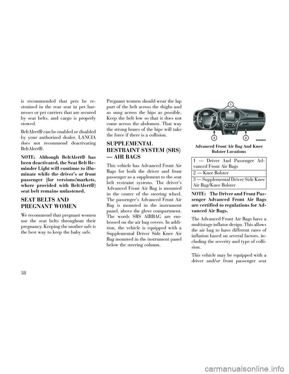
1 — Driver And Passenger Ad-
vanced Front Air Bags
2 — Knee Bolster
3 — Supplemental Driver Side Knee
Air Bag/Knee Bolster
NOTE: The Driver and Front Pas-
senger Advanced Front Air Bags
are certified to regulations for Ad-
vanced Air Bags.
The Advanced Front Air Bags have a
multistage inflator design. This allows
the air bag to have different rates of
inflation based on several factors, in-
cluding the severity and type of colli-
sion.
This vehicle may be equipped with a
driver and/or front passenger seat
Advanced Front Air Bag And Knee Bolster Locations
38
Page 46 of 332

WARNING!(Continued)
Do not put anything on or aroundthe air bag covers or attempt to
open them manually. You may
damage the air bags and you
could be injured because the air
bags may no longer be functional.
The protective covers for the air
bag cushions are designed to open
only when the air bags are inflat-
ing.
Do not drill, cut or tamper with the knee bolster in any way.
Do not mount any accessories to the knee bolster such as alarm
lights, stereos, citizen band ra-
dios, etc.
Supplemental Seat-Mounted Side
Air Bags (SAB)
Supplemental Seat-Mounted Side Air
Bags (SAB) may provide enhanced
protection to help protect an occupant
during a side impact. The SAB is
marked with an air bag label sewn
into the outboard side of the front
seats. When the air bag deploys, it opens the
seam between the front and side of the
seat’s trim cover. Each air bag deploys
independently; a left side impact de-
ploys the left air bag only and a right-
side impact deploys the right air bag
only.
Supplemental Side Air Bag
Inflatable Curtain (SABIC)
SABIC air bags may offer side-impact
protection to front and rear seat out-
board occupants in addition to that
provided by the body structure. Each
air bag features inflated chambers
placed adjacent to the head of each
outboard occupant that reduce the po-
tential for side-impact head injuries. The SABIC deploy downward, cover-
ing both windows on the impact side.
NOTE:
Air Bag covers may not be obvi-
ous in the interior trim, but they
will open during air bag deploy-
ment.
Being too close to the side air bags during deployment could
cause you to be severely injured
or killed.
SAB and SABIC air bags are a supple-
ment to the seat belt restraint system.
Occupants, including children who
are up against or very close to SAB or
SABIC air bags can be seriously in-
jured or killed. Occupants, especially
children, should not lean on or sleep
Supplemental Seat-Mounted Side Air Bag Label
Supplemental Side Air Bag InflatableCurtains (SABIC) Label Location
40
Page 55 of 332

WARNING!
Never place a rear facing infantseat in front of an air bag. A de-
ploying Passenger Advanced
Front Air Bag can cause death or
serious injury to a child 12 years
or younger, including a child in a
rearward facing infant seat.
Only use a rearward-facing child restraint in a vehicle with a rear
seat.
Older Children And Child
Restraints
Children who are two years old or who
have outgrown their rear-facing con-
vertible child seat can ride forward-
facing in the vehicle. Forward-facing
child seats and convertible child seats
used in the forward-facing direction
are for children who are over two
years old or who have outgrown the
rear-facing weight or height limit of
their rear-facing convertible child
seat. Children should remain in a
forward-facing child seat with a har-
ness for as long as possible, up to the
highest weight or height allowed by
the child seat. All children whose weight or height is
above the forward-facing limit for the
child seat should use a belt-
positioning booster seat until the ve-
hicle’s seat belts fit properly. If the
child cannot sit with knees bent over
the vehicle’s seat cushion while the
child’s back is against the seatback,
they should use a belt-positioning
booster seat. The child and belt-
positioning booster seat are held in
the vehicle by the seat belt.
WARNING!
Improper installation can lead to
failure of an infant or child re-
straint. It could come loose in a
collision. The child could be
badly injured or killed. Follow
the child restraint manufacturer’s
directions exactly when installing
an infant or child restraint.
(Continued)
WARNING!(Continued)
When your child restraint is notin use, secure it in the vehicle with
the seat belt or ISOFIX anchor-
ages, or remove it from the ve-
hicle. Do not leave it loose in the
vehicle. In a sudden stop or acci-
dent, it could strike the occupants
or seatbacks and cause serious
personal injury.
Children Too Large For Booster
Seats
Children who are large enough to
wear the shoulder belt comfortably,
and whose legs are long enough to
bend over the front of the seat when
their back is against the seatback,
should use the seat belt in a rear seat.
Use this simple 5-step test to decide
whether the child can use the vehicle’s
seat belt alone:
1. Can the child sit all the way back
against the back of the vehicle seat?
2. Do the child’s knees bend comfort-
ably over the front of the vehicle seat –
while they are still sitting all the way
back? 49
Page 61 of 332

4. Attach the connectors of the child
restraint to the lower anchorages in
the selected seating position.
5. If the child restraint has a tether
strap, connect it to the top tether an-
chorage. See the section “Installing
Child Restraints Using the Top Tether
Anchorage” for directions to attach a
tether anchor.
6. Tighten all of the straps as you
push the child restraint rearward and
downward into the seat. Remove
slack in the straps according to the
child restraint manufacturer’s in-
structions.
7. Test that the child restraint is in-
stalled tightly by pulling back and
forth on the child seat at the belt path.
It should not move more than 25.4
mm in any direction.WARNING!
Child restraint anchorages are de-
signed to withstand only those
loads imposed by correctly-fitted
child restraints. Under no circum-
stances are they to be used for adult
seat belts, harnesses, or for attach-
ing other items or equipment to the
vehicle.
How To Stow An Unused ALR
Seatbelt
When using the ISOFIX attaching
system to install a child restraint, stow
all ALR seat belts that are not being
used by other occupants or being used
to secure child restraints. An unused
belt could injure a child if they play
with it and accidentally lock the seat-
belt retractor. Before installing a child
restraint using the ISOFIX system,
buckle the seat belt behind the child
restraint and out of the child’s reach.
If the buckled seat belt interferes with
the child restraint installation, instead
of buckling it behind the child re-
straint, route the seat belt through the
child restraint belt path and then
buckle it. Do not lock the seatbelt. Remind all children in the vehicle that
the seat belts are not toys and that
they should not play with them.
WARNING!
Improper installation of a child re-
straint to the ISOFIX anchorages
can lead to failure of an infant or
child restraint. The child could be
badly injured or killed. Follow the
manufacturer's directions exactly
when installing an infant or child
restraint.
Installing Child Restraints Using
The Vehicle Seat Belt
The seat belts in the passenger seating
positions are equipped with either a
Switchable Automatic Locking Re-
tractor (ALR) or a cinching latch
plate or both. Both types of seat belts
are designed to keep the lap portion of
the seat belt tight around the child
restraint so that it is not necessary to
use a locking clip. The ALR retractor
can be “switched” into a locked mode
by pulling all of the webbing out of
55
Page 64 of 332

2. Rotate or lift the cover to access
the anchor directly behind the seat
where you are placing the child re-
straint.
3. Route the tether strap to provide
the most direct path for the strap be-
tween the anchor and the child seat. If
your vehicle is equipped with adjust-
able rear head restraints, raise the
head restraint, and where possible,
route the tether strap under the head
restraint and between the two posts. If
not possible, lower the head restraint
and pass the tether strap around the
outboard side of the head restraint.
1 — Cover A — TetherStrap Hook
3 — Attaching
Strap B — Tether An-
chor
4. Attach the tether strap hook of the
child restraint to the top tether an-
chorage as shown in the diagram. 5. Remove slack in the tether strap
according to the child restraint manu-
facturer’s instructions.
Transporting Pets
Air Bags deploying in the front seat
could harm your pet. An unrestrained
pet will be thrown about and possibly
injured, or injure a passenger during
panic braking or in a collision.
Pets should be restrained in the rear
seat in pet harnesses or pet carriers
that are secured by seat belts.
ENGINE BREAK-IN
RECOMMENDATIONS
A long break-in period is not required
for the engine and drivetrain (trans-
mission and axle) in your vehicle.
Drive moderately during the first
500 km. After the initial 100 km,
speeds up to 80 or 90 km/h are desir-
able.
While cruising, brief full-throttle ac-
celeration within the limits of local
traffic laws contributes to a good
Adjustable Headrest Release Push
Button
Adjustable Headrest DownwardPosition
Tether Strap Mounting
58
Page 67 of 332
position and interfere with the pedals
or impair safe operation of your ve-
hicle in other ways.
WARNING!
Pedals that cannot move freely can
cause loss of vehicle control and
increase the risk of serious personal
injury.
Always make sure that floor matsare properly attached to the floor
mat fasteners.
Never place or install floor mats or other floor coverings in the ve-
hicle that cannot be properly se-
cured to prevent them from mov-
ing and interfering with the
pedals or the ability to control the
vehicle.
Never put floor mats or other floor coverings on top of already
installed floor mats. Additional
floor mats and other coverings
will reduce the size of the pedal
area and interfere with the ped-
als.
(Continued)
WARNING!(Continued)
Check mounting of mats on aregular basis. Always properly re-
install and secure floor mats that
have been removed for cleaning.
Always make sure that objects cannot fall into the driver foot-
well while the vehicle is moving.
Objects can become trapped un-
der the brake pedal and accelera-
tor pedal causing a loss of vehicle
control.
If required, mounting posts must be properly installed, if not
equipped from the factory. Fail-
ure to properly follow floor mat in-
stallation or mounting can cause
interference with the brake pedal
and accelerator pedal operation
causing loss of control of the ve-
hicle.
PERIODIC SAFETY
CHECKS YOU SHOULD
MAKE OUTSIDE THE
VEHICLE
Tires
Examine tires for excessive tread wear
and uneven wear patterns. Check for
stones, nails, glass, or other objects
lodged in the tread or sidewall. In-
spect the tread for cuts and cracks.
Inspect sidewalls for cuts, cracks and
bulges. Check the wheel nuts for
tightness. Check the tires (including
spare) for proper cold inflation pres-
sure.
Lights
Have someone observe the operation
of brake lights and exterior lights
while you work the controls. Check
turn signal and high beam indicator
lights on the instrument panel.
Door Latches
Check for positive closing, latching,
and locking.
61
Page 101 of 332
GENERAL INFORMATION
This device complies with Part 15 of
the FCC rules and RSS 210 of Indus-
try Canada. Operation is subject to
the following conditions:
Changes or modifications not ex-pressly approved by the party re-
sponsible for compliance could void
the user's authority to operate the
equipment.
This device may not cause harmful interference.
This device must accept any inter- ference received, including interfer-
ence that may cause undesired op-
eration.
VOICE COMMAND
Uconnect® 8.4/8.4 Nav
The Uconnect® Voice Com-
mand system allows you to
control your AM, FM radio,
disc player, SD Card or
USB/iPod. NOTE: Take care to speak into
the Voice Command system as
calmly and normally as possible.
The ability of the Voice Command
system to recognize user voice
commands may be negatively af-
fected by rapid speaking or a
raised voice level.
WARNING!
Any voice commanded system
should be used only in safe driving
conditions following all applicable
laws, including laws regarding
phone use. Your attention should be
focused on safely operating the ve-
hicle. Failure to do so may result in
an accident causing serious injury
or death.
When you press the Uconnect® Voice
Command
button, you will hear
a beep. The beep is your signal to give
a command.
If no command is spoken the system
will say one of two responses:
I didn't understand
I didn't get that, etc., If a command is not spoken a second
time, the system will respond with an
error and give some direction as what
can be said based on the context you
are in. After three consecutive failures
of a spoken command the VR session
with end.
Pressing the Uconnect® Voice Com-
mand
button while the system is
speaking is known as “barging in.”
The system will be interrupted, and
after the beep, you can say a com-
mand. This will become helpful once
you start to learn the options.
NOTE: At any time, you can say
the words “Cancel” or “Help”.
These commands are universal and
can be used from any menu. All other
commands can be used depending
upon the active application.
When using this system, you should
speak clearly and at a normal speak-
ing volume.
The system will best recognize your
speech if the windows are closed, and
the heater/air conditioning fan is set
to low.
95
Page 115 of 332
WARNING!
Be certain that the seatback issecurely locked into position. If
the seatback is not securely
locked into position, the seat will
not provide the proper stability
for child seats and/or passengers.
An improperly latched seat could
cause serious injury.
The cargo area in the rear of the vehicle (with the rear seatbacks
in the locked-up or folded down
position) should not be used as a
play area by children when the
vehicle is in motion. They could
be seriously injured in a collision.
Children should be seated and us-
ing the proper restraint system.
DRIVER MEMORY SEAT
(for versions/markets,
where provided)
This feature allows the driver to store
up to two different memory profiles
for easy recall through a memory
switch. Each memory profile contains
desired position settings for the driver seat, side mirrors, adjustable pedals
(for versions/markets, where pro-
vided), and power tilt and telescopic
steering column (for versions/
markets, where provided) and a set of
desired radio station presets. Your Re-
mote Keyless Entry (RKE) transmit-
ter can also be programmed to recall
the same positions when the UN-
LOCK button is pressed.
NOTE:
Only one RKE transmitter can
be linked to each of the memory
positions.
Passive Entry door handles can- not be linked to the memory
function. Use either the memory
recall switch or the RKE trans-
mitter (if linked to the memory
feature) to recall memory posi-
tions 1 or 2.
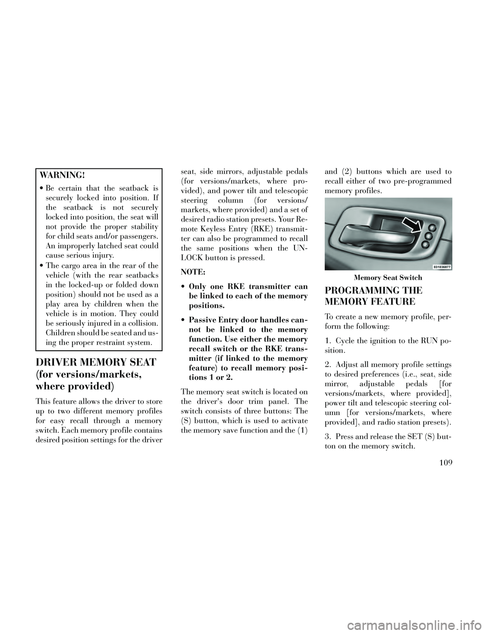
The memory seat switch is located on
the driver's door trim panel. The
switch consists of three buttons: The
(S) button, which is used to activate
the memory save function and the (1) and (2) buttons which are used to
recall either of two pre-programmed
memory profiles.
PROGRAMMING THE
MEMORY FEATURE
To create a new memory profile, per-
form the following:
1. Cycle the ignition to the RUN po-
sition.
2. Adjust all memory profile settings
to desired preferences (i.e., seat, side
mirror, adjustable pedals [for
versions/markets, where provided],
power tilt and telescopic steering col-
umn [for versions/markets, where
provided], and radio station presets).
3. Press and release the SET (S) but-
ton on the memory switch.
Memory Seat Switch
109
Page 118 of 332
NOTE: Your vehicle may be
equipped with an Active Hood Sys-
tem. Refer to “Occupant Re-
straints” in “Things To Know Be-
fore Starting Your Vehicle” for
further information.
CAUTION!
To prevent possible damage, do not
slam the hood to close it. Lower the
hood until it is open approximately
15 cm, and then drop it. This
should secure both latches. Never
drive your vehicle unless the hood is
fully closed, with both latches en-
gaged.
WARNING!
Be sure the hood is fully latched
before driving your vehicle. If the
hood is not fully latched, it could
open when the vehicle is in motion
and block your vision. Failure to
follow this warning could result in
serious injury or death.
LIGHTS
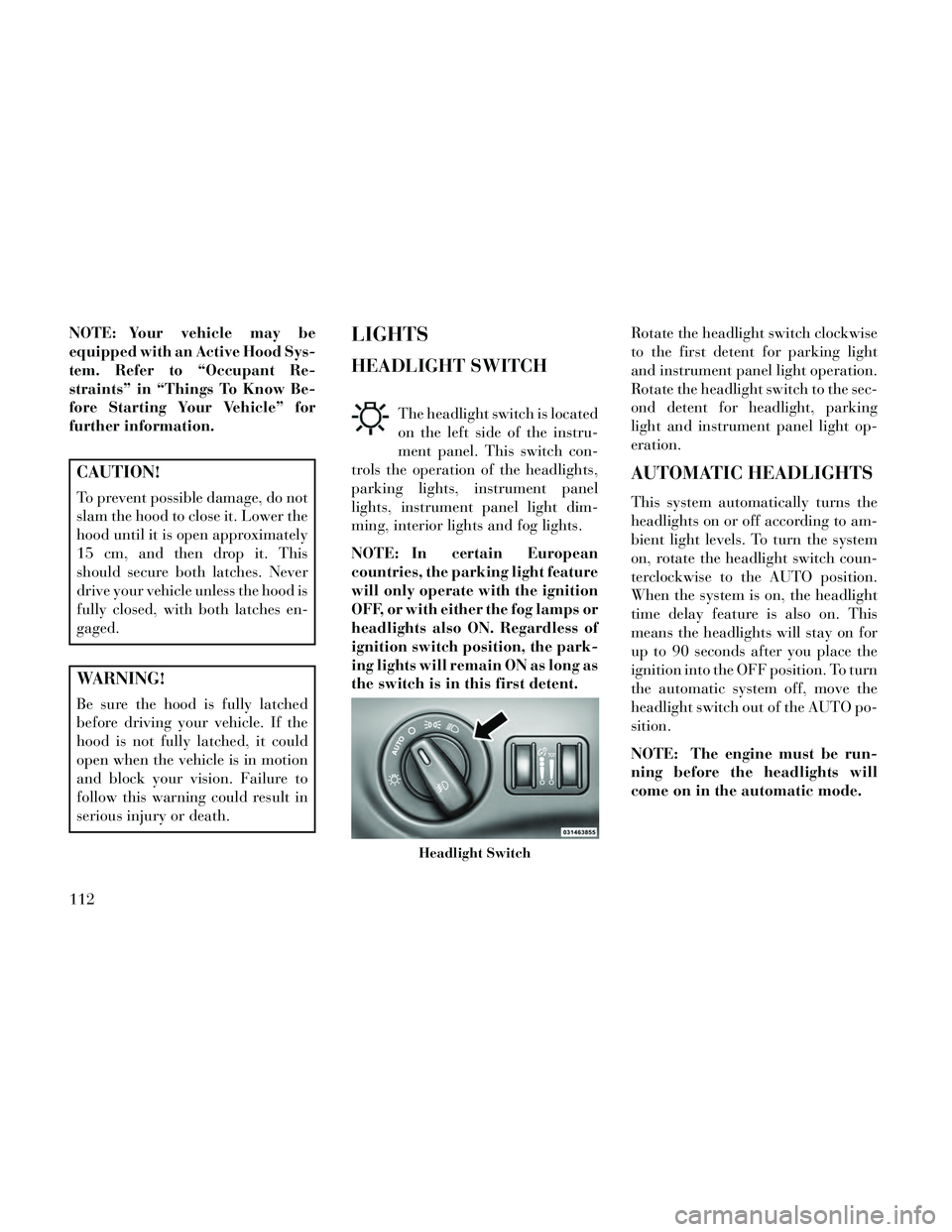
HEADLIGHT SWITCH
The headlight switch is located
on the left side of the instru-
ment panel. This switch con-
trols the operation of the headlights,
parking lights, instrument panel
lights, instrument panel light dim-
ming, interior lights and fog lights.
NOTE: In certain European
countries, the parking light feature
will only operate with the ignition
OFF, or with either the fog lamps or
headlights also ON. Regardless of
ignition switch position, the park-
ing lights will remain ON as long as
the switch is in this first detent. Rotate the headlight switch clockwise
to the first detent for parking light
and instrument panel light operation.
Rotate the headlight switch to the sec-
ond detent for headlight, parking
light and instrument panel light op-
eration.
AUTOMATIC HEADLIGHTS
This system automatically turns the
headlights on or off according to am-
bient light levels. To turn the system
on, rotate the headlight switch coun-
terclockwise to the AUTO position.
When the system is on, the headlight
time delay feature is also on. This
means the headlights will stay on for
up to 90 seconds after you place the
ignition into the OFF position. To turn
the automatic system off, move the
headlight switch out of the AUTO po-
sition.
NOTE: The engine must be run-
ning before the headlights will
come on in the automatic mode.
Headlight Switch
112
Page 150 of 332

SUNGLASS BIN DOOR
At the front of the console a compart-
ment is provided for the storage of a
pair of sunglasses. The storage com-
partment access is a “push/push” de-
sign. Push the chrome pad on the door
to open. Push the chrome pad on the
door to close.
COMMANDVIEW®
SUNROOF WITH POWER
SHADE — (for
versions/markets, where
provided)
The CommandView® sunroof switch
is located to the left between the sun
visors on the overhead console.The power shade switch is located to
the right between the sun visors on the
overhead console.
WARNING!
Never leave children unattended
in a vehicle, and do not let chil-
dren play with the sun roof. Do
not leave the key fob in or near
the vehicle, or in a location acces-
sible to children, and do not leave
the ignition of a vehicle equipped
with Keyless Enter-N-Go in the
ACC or ON/RUN mode. Occu-
pants, particularly unattended
children, can become entrapped
by the power sunroof while oper-
ating the power sunroof switch.
Such entrapment may result in
serious injury or death.
(Continued)
WARNING!(Continued)
In a collision, there is a greater
risk of being thrown from a ve-
hicle with an open sunroof. You
could also be seriously injured or
killed. Always fasten your seat
belt properly and make sure all
passengers are properly secured
too.
Do not allow small children to operate the sunroof. Never allow
your fingers, other body parts, or
any object to project through the
sunroof opening. Injury may re-
sult.
OPENING SUNROOF —
EXPRESS
Press the switch rearward and release
it within one-half second and the sun-
roof will open automatically from any
position. The sunroof will open fully
and stop automatically. This is called
“Express Open”. During Express
Open operation, any movement of the
sunroof switch will stop the sunroof.
Sunglass Bin Door
CommandView® Sunroof And Power
Shade Switches
144