instrument panel Lancia Thema 2014 Owner handbook (in English)
[x] Cancel search | Manufacturer: LANCIA, Model Year: 2014, Model line: Thema, Model: Lancia Thema 2014Pages: 332, PDF Size: 3.46 MB
Page 44 of 332
is recommended that pets be re-
strained in the rear seat in pet har-
nesses or pet carriers that are secured
by seat belts, and cargo is properly
stowed.
BeltAlert® can be enabled or disabled
by your authorized dealer. LANCIA
does not recommend deactivating
BeltAlert®.
NOTE: Although BeltAlert® has
been deactivated, the Seat Belt Re-
minder Light will continue to illu-
minate while the driver’s or front
passenger (for versions/markets,
where provided with BeltAlert®)
seat belt remains unfastened.
SEAT BELTS AND
PREGNANT WOMEN
We recommend that pregnant women
use the seat belts throughout their
pregnancy. Keeping the mother safe is
the best way to keep the baby safe.Pregnant women should wear the lap
part of the belt across the thighs and
as snug across the hips as possible.
Keep the belt low so that it does not
come across the abdomen. That way
the strong bones of the hips will take
the force if there is a collision.
SUPPLEMENTAL
RESTRAINT SYSTEM (SRS)
— AIR BAGS
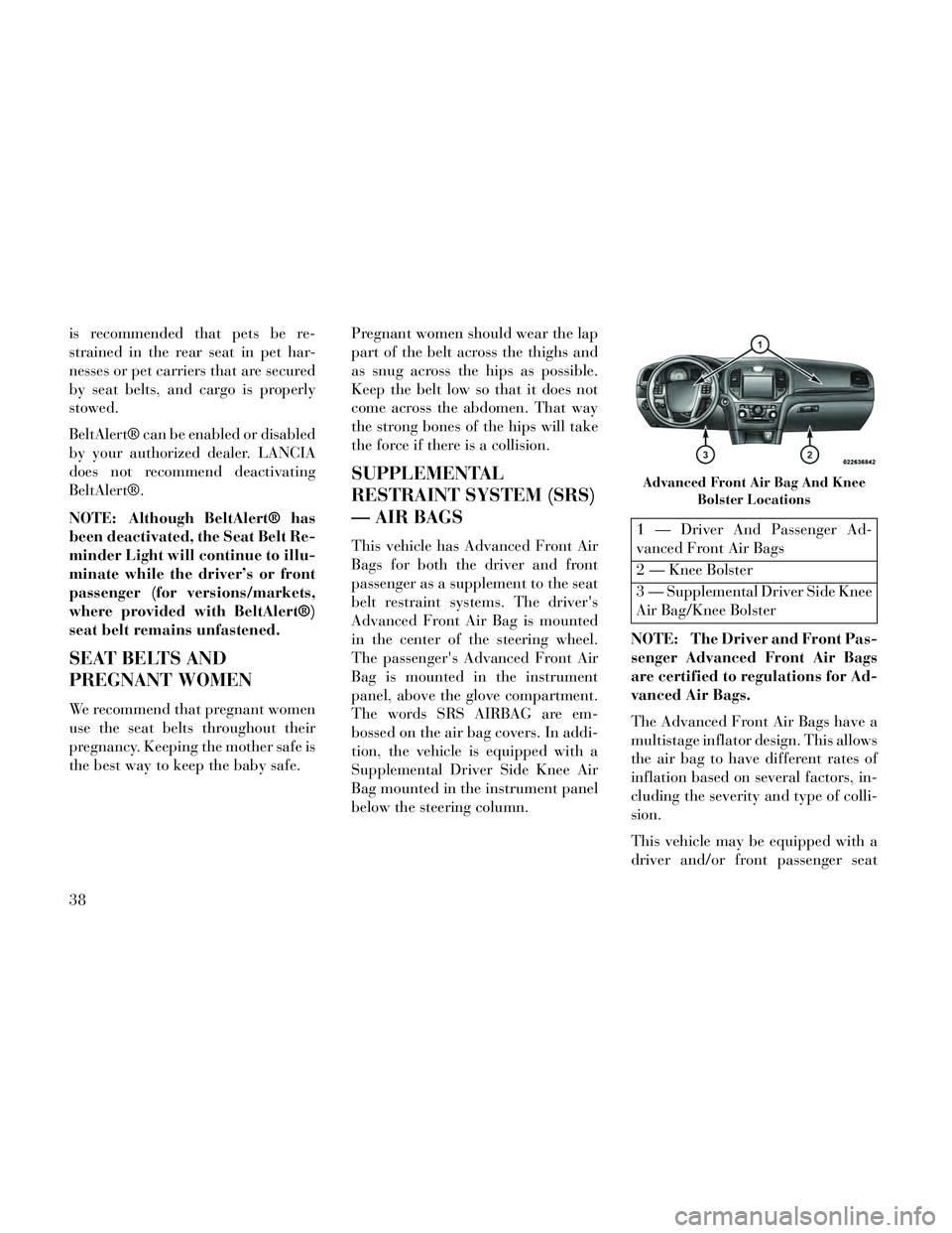
This vehicle has Advanced Front Air
Bags for both the driver and front
passenger as a supplement to the seat
belt restraint systems. The driver's
Advanced Front Air Bag is mounted
in the center of the steering wheel.
The passenger's Advanced Front Air
Bag is mounted in the instrument
panel, above the glove compartment.
The words SRS AIRBAG are em-
bossed on the air bag covers. In addi-
tion, the vehicle is equipped with a
Supplemental Driver Side Knee Air
Bag mounted in the instrument panel
below the steering column.
1 — Driver And Passenger Ad-
vanced Front Air Bags
2 — Knee Bolster
3 — Supplemental Driver Side Knee
Air Bag/Knee Bolster
NOTE: The Driver and Front Pas-
senger Advanced Front Air Bags
are certified to regulations for Ad-
vanced Air Bags.
The Advanced Front Air Bags have a
multistage inflator design. This allows
the air bag to have different rates of
inflation based on several factors, in-
cluding the severity and type of colli-
sion.
This vehicle may be equipped with a
driver and/or front passenger seat
Advanced Front Air Bag And Knee Bolster Locations
38
Page 45 of 332
belt buckle switch that detects
whether the driver or front passenger
seat belt is fastened. The seat belt
buckle switch may adjust the inflation
rate of the Advanced Front Air Bags.
This vehicle is equipped with Supple-
mental Side Air Bag Inflatable Cur-
tains (SABIC) to protect the driver,
front, and rear passengers sitting next
to a window. The SABIC air bags are
located above the side windows and
their covers are also labeled: SRS
AIRBAG.
This vehicle is equipped with Supple-
mental Seat-Mounted Side Air Bags
(SAB) to provide enhanced protection
for an occupant during a side impact.
The Supplemental Seat-Mounted
Side Air Bags are located in the out-
board side of the front seats.
NOTE:
Air Bag covers may not be obvi-ous in the interior trim, but they
will open during air bag deploy-
ment. After any accident, the vehicle
should be taken to an autho-
rized dealer immediately.
Air Bag System Components
Your vehicle may be equipped with
the following air bag system compo-
nents:
Occupant Restraint Controller (ORC)
Air Bag Warning Light
Steering Wheel and Column
Instrument Panel
Supplemental Driver Side Knee Air Bag
Knee Impact Bolsters
Driver Advanced Front Air Bag
Passenger Advanced Front Air Bag
Supplemental Seat-Mounted Side Air Bags (SAB)
Supplemental Side Air Bag Inflat- able Curtains (SABIC)
Front and Side Impact Sensors (for versions/markets, where provided) Front Seat Belt Pretensioners, Seat
Belt Buckle Switch
Advanced Front Air Bag Features
The Advanced Front Air Bag system
has multistage driver and front pas-
senger air bags. This system provides
output appropriate to the severity and
type of collision as determined by the
Occupant Restraint Controller
(ORC), which may receive informa-
tion from the front impact sensors.
The first stage inflator is triggered
immediately during an impact that
requires air bag deployment. This low
output is used in less severe collisions.
A higher energy output is used for
more severe collisions.
WARNING!
No objects should be placed over or near the air bag on the instru-
ment panel, because any such ob-
jects could cause harm if the ve-
hicle is in a collision severe
enough to cause the air bag to
inflate.
(Continued)
39
Page 48 of 332

Advanced Front Air Bags and Supple-
mental Driver Side Knee Air Bag are
designed to provide additional protec-
tion by supplementing the seat belts
in certain frontal collisions depending
on several factors, including the se-
verity and type of collision. Advanced
Front Air Bags and Supplemental
Driver Side Knee Air Bag are not ex-
pected to reduce the risk of injury in
rear, side, or rollover collisions.
The Advanced Front Air Bags and
Supplemental Driver Side Knee Air
Bag will not deploy in all frontal col-
lisions, including some that may pro-
duce substantial vehicle damage —
for example, some pole collisions,
truck underrides, and angle offset col-
lisions. On the other hand, depending
on the type and location of impact,
Advanced Front Air Bags may deploy
in crashes with little vehicle front-end
damage but that produce a severe ini-
tial deceleration.
The side air bags will not deploy in all
side collisions. Side air bag deploy-
ment will depend on the severity and
type of collision.Because air bag sensors measure ve-
hicle deceleration over time, vehicle
speed and damage by themselves are
not good indicators of whether or not
an air bag should have deployed.
Seat belts are necessary for your pro-
tection in all collisions, and also are
needed to help keep you in position,
away from an inflating air bag.
The ORC monitors the readiness of
the electronic parts of the air bag sys-
tem whenever the ignition is in the
START or ON/RUN position. If the
ignition is in the OFF position or in
the ACC position, the air bag system is
not on and the air bags will not in-
flate.
The ORC contains a backup power
supply system that may deploy the air
bags even if the battery loses power or
it becomes disconnected prior to de-
ployment.
Also, the ORC turns on the
Air Bag Warning Light in
the instrument panel for
approximately four to eight seconds for a self-check when the ig-
nition is first turned on. After the self-
check, the Air Bag Warning Light will
turn off. If the ORC detects a mal-
function in any part of the system, it
turns on the Air Bag Warning Light,
either momentarily or continuously. A
single chime will sound if the light
comes on again after initial startup.
It also includes diagnostics that will
illuminate the instrument cluster Air
Bag Warning Light if a malfunction is
noted that could affect the air bag
system. The diagnostics also record
the nature of the malfunction.
WARNING!
Ignoring the Air Bag Warning Light
in your instrument panel could
mean you won't have the air bags to
protect you in a collision. If the light
does not come on as a bulb check
when the ignition is first turned on,
stays on after you start the vehicle,
or if it comes on as you drive, have
an authorized dealer service the air
bag system immediately.
42
Page 49 of 332
Driver And Passenger Advanced
Front Air Bag Inflator Units
The Driver and Passenger Advanced
Front Air Bag Inflator Units are lo-
cated in the center of the steering
wheel and on the right side of the
instrument panel. When the ORC de-
tects a collision requiring the Ad-
vanced Front Air Bags, it signals the
inflator units. A large quantity of non-
toxic gas is generated to inflate the
Advanced Front Air Bags. Different
air bag inflation rates are possible,
based on several factors, including the
collision type and severity. The steer-
ing wheel hub trim cover and the up-
per right side of the instrument panel
separate and fold out of the way as the
air bags inflate to their full size. The
air bags fully inflate in about 50 to 70
milliseconds. This is about half of the
time it takes to blink your eyes. The
air bags then quickly deflate while
helping to restrain the driver and
front passenger.
The Advanced Front Air Bag gas is
vented through the vent holes in thesides of the air bag. In this way, the air
bags do not interfere with your con-
trol of the vehicle.
Supplemental Driver Side Knee
Air Bag Inflator Unit
The Supplemental Driver Side Knee
Air Bag unit is located in the instru-
ment panel trim beneath the steering
column. When the ORC detects a col-
lision requiring the Advanced Front
Air Bags, it signals the inflator units.
A large quantity of non-toxic gas is
generated to inflate the Supplemental
Driver Side Knee Air Bag. The trim
cover separates and folds out of the
way allowing the air bag to inflate to
the full size. The air bag fully inflates
in about 15 to 20 milliseconds.
Supplemental Seat-Mounted Side
Air Bag (SAB) Inflator Units
The Supplemental Seat-Mounted
Side Air Bags (SAB) are designed to
activate only in certain side collisions.
The ORC determines if a side collision
requires the side air bags to inflate,
based on the severity and type of col-
lision.Based on the severity and type of col-
lision, the side air bag inflator on the
crash side of the vehicle may be trig-
gered, releasing a quantity of non-
toxic gas. The inflating SAB exits
through the seat seam into the space
between the occupant and the door.
The SAB fully inflates in about 10
milliseconds. The side air bag moves
at a very high speed and with such a
high force that it could injure you if
you are not seated properly, or if items
are positioned in the area where the
side air bag inflates. This especially
applies to children.
Supplemental Side Air Bag
Inflatable Curtain (SABIC)
Inflator Units
During collisions where the impact is
confined to a particular area of the
side of the vehicle, the ORC may de-
ploy the SABIC air bags, depending
on the severity and type of collision. In
these events, the ORC will deploy the
SABIC only on the impact side of the
vehicle.
A quantity of non-toxic gas is gener-
ated to inflate the side curtain air bag.
43
Page 51 of 332
As the air bags deflate, you may seesome smoke-like particles. The
particles are a normal by-product
of the process that generates the
non-toxic gas used for air bag infla-
tion. These airborne particles may
irritate the skin, eyes, nose, or
throat. If you have skin or eye irri-
tation, rinse the area with cool wa-
ter. For nose or throat irritation,
move to fresh air. If the irritation
continues, see your doctor. If these
particles settle on your clothing,
follow the garment manufacturer's
instructions for cleaning.
Do not drive your vehicle after the air
bags have deployed. If you are in-
volved in another collision, the air bags
will not be in place to protect you.
WARNING!
Deployed air bags and seat belt pre-
tensioners cannot protect you in
another collision. Have the air
bags, seat belt pretensioners, and
the front seat belt retractor assem-
blies replaced by an authorized
dealer immediately. Also, have the
Occupant Restraint Controller Sys-
tem serviced as well. Maintaining Your Air Bag System
WARNING!
Modifications to any part of the
air bag system could cause it to
fail when you need it. You could
be injured if the air bag system is
not there to protect you. Do not
modify the components or wiring,
including adding any kind of
badges or stickers to the steering
wheel hub trim cover or the upper
right side of the instrument panel.
Do not modify the front bumper,
vehicle body structure, or add af-
termarket side steps or running
boards.
It is dangerous to try to repair any part of the air bag system your-
self. Be sure to tell anyone who
works on your vehicle that it has
an air bag system.
(Continued)
WARNING!(Continued)
Do not attempt to modify anypart of your air bag system. The
air bag may inflate accidentally
or may not function properly if
modifications are made. Take
your vehicle to an authorized
dealer for any air bag system ser-
vice. If your seat, including your
trim cover and cushion, needs to
be serviced in any way (including
removal or loosening/tightening
of seat attachment bolts), take
the vehicle to your authorized
dealer. Only manufacturer ap-
proved seat accessories may be
used. If it is necessary to modify
the air bag system for persons
with disabilities, contact your au-
thorized dealer.
Air Bag Warning Light
You will want to have the
air bags ready to inflate for
your protection in a colli-
sion. The Air Bag Warning
Light monitors the internal circuits
45
Page 67 of 332
position and interfere with the pedals
or impair safe operation of your ve-
hicle in other ways.
WARNING!
Pedals that cannot move freely can
cause loss of vehicle control and
increase the risk of serious personal
injury.
Always make sure that floor matsare properly attached to the floor
mat fasteners.
Never place or install floor mats or other floor coverings in the ve-
hicle that cannot be properly se-
cured to prevent them from mov-
ing and interfering with the
pedals or the ability to control the
vehicle.
Never put floor mats or other floor coverings on top of already
installed floor mats. Additional
floor mats and other coverings
will reduce the size of the pedal
area and interfere with the ped-
als.
(Continued)
WARNING!(Continued)
Check mounting of mats on aregular basis. Always properly re-
install and secure floor mats that
have been removed for cleaning.
Always make sure that objects cannot fall into the driver foot-
well while the vehicle is moving.
Objects can become trapped un-
der the brake pedal and accelera-
tor pedal causing a loss of vehicle
control.
If required, mounting posts must be properly installed, if not
equipped from the factory. Fail-
ure to properly follow floor mat in-
stallation or mounting can cause
interference with the brake pedal
and accelerator pedal operation
causing loss of control of the ve-
hicle.
PERIODIC SAFETY
CHECKS YOU SHOULD
MAKE OUTSIDE THE
VEHICLE
Tires
Examine tires for excessive tread wear
and uneven wear patterns. Check for
stones, nails, glass, or other objects
lodged in the tread or sidewall. In-
spect the tread for cuts and cracks.
Inspect sidewalls for cuts, cracks and
bulges. Check the wheel nuts for
tightness. Check the tires (including
spare) for proper cold inflation pres-
sure.
Lights
Have someone observe the operation
of brake lights and exterior lights
while you work the controls. Check
turn signal and high beam indicator
lights on the instrument panel.
Door Latches
Check for positive closing, latching,
and locking.
61
Page 82 of 332

NOTE: In a parking lot situation,
oncoming vehicles can be ob-
scured by vehicles parked on ei-
ther side. If the sensors are
blocked by other structures or ve-
hicles, the system will not be able
to alert the driver.
When RCP is on and the vehicle is in
REVERSE, the driver is alerted using
both the visual and audible alarms,
including reducing the radio volume.
WARNING!
RCP is not a Back Up Aid system. It
is intended to be used to help a
driver detect an oncoming vehicle
in a parking lot situation. Drivers
must be careful when backing up,
even when using RCP. Always
check carefully behind your ve-
hicle, look behind you, and be sure
to check for pedestrians, animals,
other vehicles, obstructions, and
blind spots before backing up. Fail-
ure to do so can result in serious
injury or death.
MODES OF OPERATION
Modes Of Operation With EVIC
Three selectable modes of operation
are available in the Electronic Vehicle
Information Center (EVIC). Refer to
“Electronic Vehicle Information Cen-
ter (EVIC)/Personal Settings
(Customer-Programmable Features)”
in “Understanding Your Instrument
Panel” for further information.
Modes Of Operation With
Uconnect® System — (for
versions/markets, where pro-
vided)
Three selectable modes of operation
are available in the Uconnect® sys-
tem screen. Refer to “Customer- Pro-
grammable Features — Uconnect®
Access settings ” in “Understanding
Your Instrument Panel” for further
information.
Blind Spot Alert
When operating in Blind Spot Alert
mode, the BSM system will provide a
visual alert in the appropriate sideview mirror based on a detected ob-
ject. However, when the system is op-
erating in RCP, the system will re-
spond with both visual and audible
alerts when a detected object is pres-
ent. Whenever an audible alert is re-
quested, the radio volume is reduced.
Blind Spot Alert Lights/Chime
When operating in Blind Spot Alert
Lights/Chime mode, the BSM system
will provide a visual alert in the ap-
propriate side view mirror based on a
detected object. If the turn signal is
then activated, and it corresponds to
an alert present on that side of the
vehicle, an audible chime will also be
sounded. Whenever a turn signal and
detected object are present on the
same side at the same time, both the
visual and audio alerts will be issued.
In addition to the audible alert, the
radio (if on) volume will be reduced.
NOTE:
Whenever an audible alert is re-
quested by the BSM system, the
radio volume is reduced.
76
Page 116 of 332
4. Within five seconds, press and re-
lease the MEMORY button 1 or 2. The
Electronic Vehicle Information Center
will display which memory position
has been set.
NOTE:
Memory profiles can be set with-out the vehicle in PARK, but the
vehicle must be in PARK to re-
call a memory profile.
The Recall Memory with Remote Key Unlock feature can be
turned on and off using the
Uconnect® System, refer to
“Uconnect® Settings” in “Un-
derstanding Your Instrument
Panel” for further information.
LINKING AND UNLINKING
THE REMOTE KEYLESS
ENTRY TRANSMITTER TO
MEMORY
Your RKE transmitters can be pro-
grammed to recall one of two pre-
programmed memory profiles by
pressing the UNLOCK button on the
RKE transmitter. NOTE: Before programming your
RKE transmitters you must select
the “Memory To FOB” feature
through the Uconnect® system
screen. Refer to “Customer- Pro-
grammable Features —
Uconnect® Access 8.4 Settings ” in
“Understanding Your Instrument
Panel” for further information.
To program your RKE transmitters,
perform the following:
1. Cycle the ignition to the OFF posi-
tion.
2. Select desired memory profile (1)
or (2).
3. Once the profile has been recalled,
press and release the SET (S) button
on the memory switch, then press and
release button (1) or (2) accordingly.
“Memory Profile Set” (1 or 2) will
display in the instrument cluster on
vehicles equipped with the EVIC.
4. Press and release the LOCK but-
ton on the RKE transmitter within 10
seconds.
NOTE: Your RKE transmitters
can be unlinked to your memory
settings by pressing the SET (S)
button followed by the UNLOCK
button on the RKE transmitter in
Step 4 above.
MEMORY POSITION
RECALL
NOTE: The vehicle must be in
PARK to recall memory positions.
If a recall is attempted when the
vehicle is not in PARK, a message
will display in the EVIC.
To recall the memory settings for
driver, press MEMORY button num-
ber (1) on the driver's door or the
UNLOCK button on the RKE trans-
mitter linked to memory position 1.
To recall the memory setting for
driver, press MEMORY button num-
ber (2) on the driver's door or the
UNLOCK button on the RKE trans-
mitter linked to memory position 2.
A recall can be cancelled by pressing
any of the MEMORY buttons (S, 1, or
2) on the driver's door during a recall.
When a recall is cancelled, the driver
110
Page 117 of 332

seat, side mirror, adjustable pedals
(for versions/markets, where pro-
vided), and power tilt and telescopic
steering column (for versions/
markets, where provided) stop mov-
ing. A delay of one second will occur
before another recall can be selected.
EASY ENTRY/EXIT SEAT
(Available With Memory
Seat Only)
This feature provides automatic
driver seat positioning to enhance
driver mobility when entering and ex-
iting the vehicle.
The distance the driver seat moves
depends on where you have the driver
seat positioned when you place the
ignition to the OFF position.
When you cycle the ignition to theOFF position, the driver seat will
move about 60 mm rearward if the
driver seat position is greater than
or equal to 68 mm forward of the
rear stop. The seat will return to its
previously set position when you
place the ignition into the ACC or
RUN position. When you cycle the ignition to the
OFF position, the driver seat will
move to a position 8 mm forward of
the rear stop if the driver seat posi-
tion is between 23 mm and 68 mm
forward of the rear stop. The seat
will return to its previously set po-
sition when you place the ignition
to the ACC or RUN position.
The Easy Entry/Easy Exit feature is disabled when the driver seat po-
sition is less than 23 mm forward of
the rear stop. At this position, there
is no benefit to the driver by moving
the seat for Easy Exit or Easy En-
try.
Each stored memory setting will have
an associated Easy Entry and Easy
Exit position.
NOTE: The Easy Entry/Easy Exit
feature can be enabled or disabled
using the Uconnect® System, refer
to “Uconnect® Settings” in “Un-
derstanding Your Instrument
Panel” for further information.
TO OPEN AND CLOSE
THE HOOD
Two latches must be released to open
the hood.
1. Pull the hood release lever located
under the left side of the instrument
panel.
2. Move to the outside of the vehicle
and push the safety catch to the left.
The safety catch is located under the
center front edge of the hood.
Hood Release Lever
Hood Safety Latch
111
Page 118 of 332
NOTE: Your vehicle may be
equipped with an Active Hood Sys-
tem. Refer to “Occupant Re-
straints” in “Things To Know Be-
fore Starting Your Vehicle” for
further information.
CAUTION!
To prevent possible damage, do not
slam the hood to close it. Lower the
hood until it is open approximately
15 cm, and then drop it. This
should secure both latches. Never
drive your vehicle unless the hood is
fully closed, with both latches en-
gaged.
WARNING!
Be sure the hood is fully latched
before driving your vehicle. If the
hood is not fully latched, it could
open when the vehicle is in motion
and block your vision. Failure to
follow this warning could result in
serious injury or death.
LIGHTS
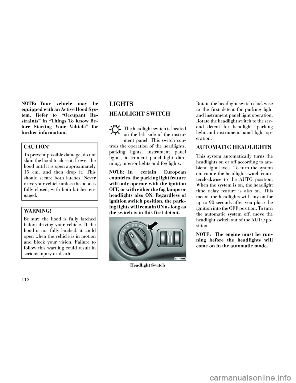
HEADLIGHT SWITCH
The headlight switch is located
on the left side of the instru-
ment panel. This switch con-
trols the operation of the headlights,
parking lights, instrument panel
lights, instrument panel light dim-
ming, interior lights and fog lights.
NOTE: In certain European
countries, the parking light feature
will only operate with the ignition
OFF, or with either the fog lamps or
headlights also ON. Regardless of
ignition switch position, the park-
ing lights will remain ON as long as
the switch is in this first detent. Rotate the headlight switch clockwise
to the first detent for parking light
and instrument panel light operation.
Rotate the headlight switch to the sec-
ond detent for headlight, parking
light and instrument panel light op-
eration.
AUTOMATIC HEADLIGHTS
This system automatically turns the
headlights on or off according to am-
bient light levels. To turn the system
on, rotate the headlight switch coun-
terclockwise to the AUTO position.
When the system is on, the headlight
time delay feature is also on. This
means the headlights will stay on for
up to 90 seconds after you place the
ignition into the OFF position. To turn
the automatic system off, move the
headlight switch out of the AUTO po-
sition.
NOTE: The engine must be run-
ning before the headlights will
come on in the automatic mode.
Headlight Switch
112