warning Lancia Thema 2014 Owner handbook (in English)
[x] Cancel search | Manufacturer: LANCIA, Model Year: 2014, Model line: Thema, Model: Lancia Thema 2014Pages: 332, PDF Size: 3.46 MB
Page 101 of 332
GENERAL INFORMATION
This device complies with Part 15 of
the FCC rules and RSS 210 of Indus-
try Canada. Operation is subject to
the following conditions:
Changes or modifications not ex-pressly approved by the party re-
sponsible for compliance could void
the user's authority to operate the
equipment.
This device may not cause harmful interference.
This device must accept any inter- ference received, including interfer-
ence that may cause undesired op-
eration.
VOICE COMMAND
Uconnect® 8.4/8.4 Nav
The Uconnect® Voice Com-
mand system allows you to
control your AM, FM radio,
disc player, SD Card or
USB/iPod. NOTE: Take care to speak into
the Voice Command system as
calmly and normally as possible.
The ability of the Voice Command
system to recognize user voice
commands may be negatively af-
fected by rapid speaking or a
raised voice level.
WARNING!
Any voice commanded system
should be used only in safe driving
conditions following all applicable
laws, including laws regarding
phone use. Your attention should be
focused on safely operating the ve-
hicle. Failure to do so may result in
an accident causing serious injury
or death.
When you press the Uconnect® Voice
Command
button, you will hear
a beep. The beep is your signal to give
a command.
If no command is spoken the system
will say one of two responses:
I didn't understand
I didn't get that, etc., If a command is not spoken a second
time, the system will respond with an
error and give some direction as what
can be said based on the context you
are in. After three consecutive failures
of a spoken command the VR session
with end.
Pressing the Uconnect® Voice Com-
mand
button while the system is
speaking is known as “barging in.”
The system will be interrupted, and
after the beep, you can say a com-
mand. This will become helpful once
you start to learn the options.
NOTE: At any time, you can say
the words “Cancel” or “Help”.
These commands are universal and
can be used from any menu. All other
commands can be used depending
upon the active application.
When using this system, you should
speak clearly and at a normal speak-
ing volume.
The system will best recognize your
speech if the windows are closed, and
the heater/air conditioning fan is set
to low.
95
Page 109 of 332
SEATS
Seats are a part of the Occupant Re-
straint System of the vehicle.
WARNING!
It is dangerous to ride in a cargoarea, inside or outside of a ve-
hicle. In a collision, people riding
in these areas are more likely to
be seriously injured or killed.
Do not allow people to ride in any area of your vehicle that is not
equipped with seats and seat
belts. In a collision, people riding
in these areas are more likely to
be seriously injured or killed.
Be sure everyone in your vehicle is in a seat and using a seat belt
properly.
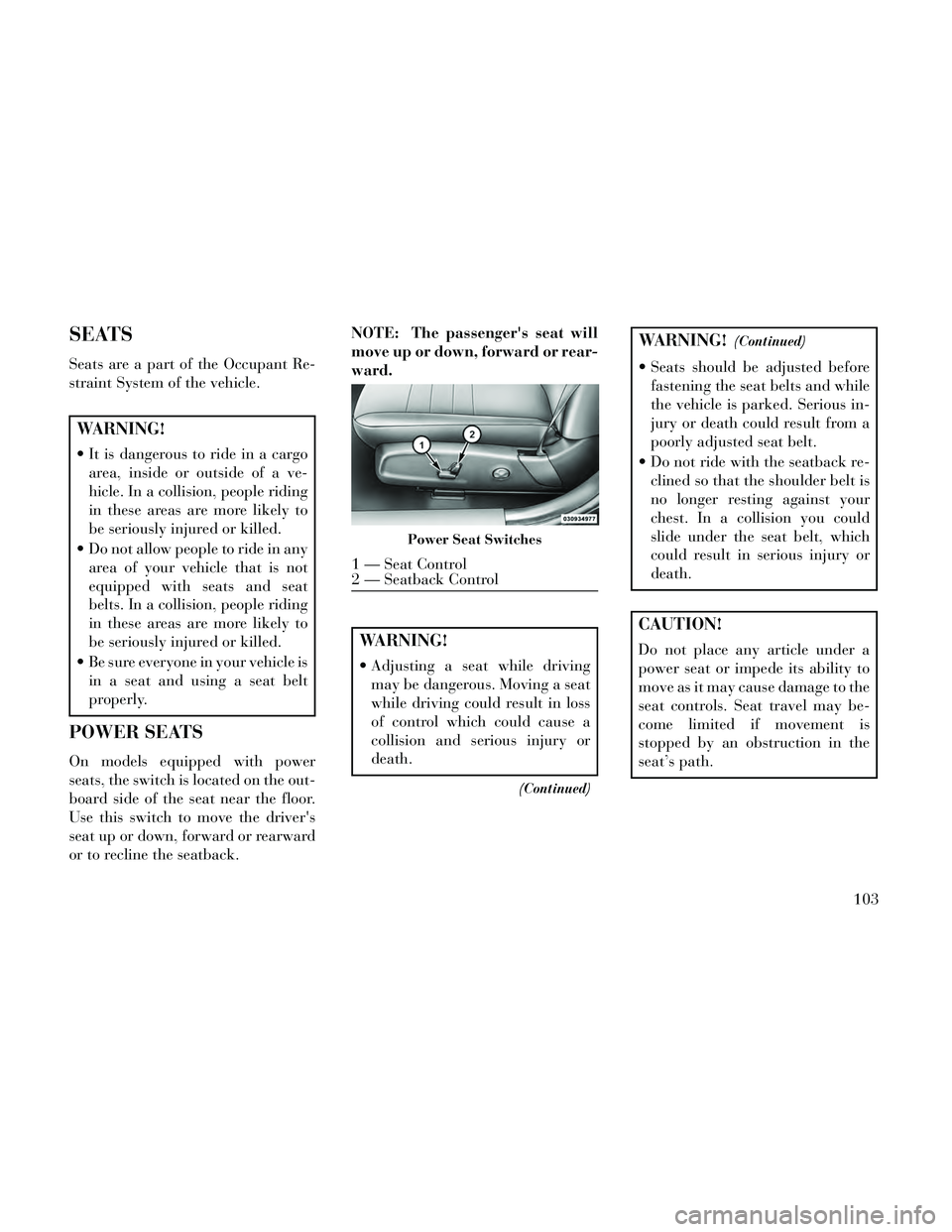
POWER SEATS
On models equipped with power
seats, the switch is located on the out-
board side of the seat near the floor.
Use this switch to move the driver's
seat up or down, forward or rearward
or to recline the seatback. NOTE: The passenger's seat will
move up or down, forward or rear-
ward.
WARNING!
Adjusting a seat while driving
may be dangerous. Moving a seat
while driving could result in loss
of control which could cause a
collision and serious injury or
death.
(Continued)
WARNING!(Continued)
Seats should be adjusted beforefastening the seat belts and while
the vehicle is parked. Serious in-
jury or death could result from a
poorly adjusted seat belt.
Do not ride with the seatback re- clined so that the shoulder belt is
no longer resting against your
chest. In a collision you could
slide under the seat belt, which
could result in serious injury or
death.
CAUTION!
Do not place any article under a
power seat or impede its ability to
move as it may cause damage to the
seat controls. Seat travel may be-
come limited if movement is
stopped by an obstruction in the
seat’s path.
Power Seat Switches
1 — Seat Control
2 — Seatback Control
103
Page 110 of 332
Adjusting The Seat Forward Or
Rearward
The seat can be adjusted both forward
and rearward. Push the seat switch
forward or rearward, the seat will
move in the direction of the switch.
Release the switch when the desired
position has been reached.
Adjusting The Seat Up Or Down
The height of the seats can be ad-
justed up or down. Pull upward or
push downward on the seat switch,
the seat will move in the direction of
the switch. Release the switch when
the desired position is reached.
Tilting The Seat Up Or Down
The angle of the seat cushion can be
adjusted in four directions. Pull up-
ward or push downward on the front
or rear of the seat switch, the front or
rear of the seat cushion will move in
the direction of the switch. Release the
switch when the desired position has
been reached.Reclining The Seatback
The angle of the seatback can be ad-
justed forward or rearward. Push the
seatback switch forward or rearward,
the seat will move in the direction of
the switch. Release the switch when
the desired position is reached.
WARNING!
Adjusting a seat while driving
may be dangerous. Moving a seat
while driving could result in loss
of control which could cause a
collision and serious injury or
death.
Seats should be adjusted before fastening the seat belts and while
the vehicle is parked. Serious in-
jury or death could result from a
poorly adjusted seat belt.
Do not ride with the seatback re- clined so that the shoulder belt is
no longer resting against your
chest. In a collision you could
slide under the seat belt, which
could result in serious injury or
death.
CAUTION!
Do not place any article under a
power seat or impede its ability to
move as it may cause damage to the
seat controls. Seat travel may be-
come limited if movement is
stopped by an obstruction in the
seat’s path.
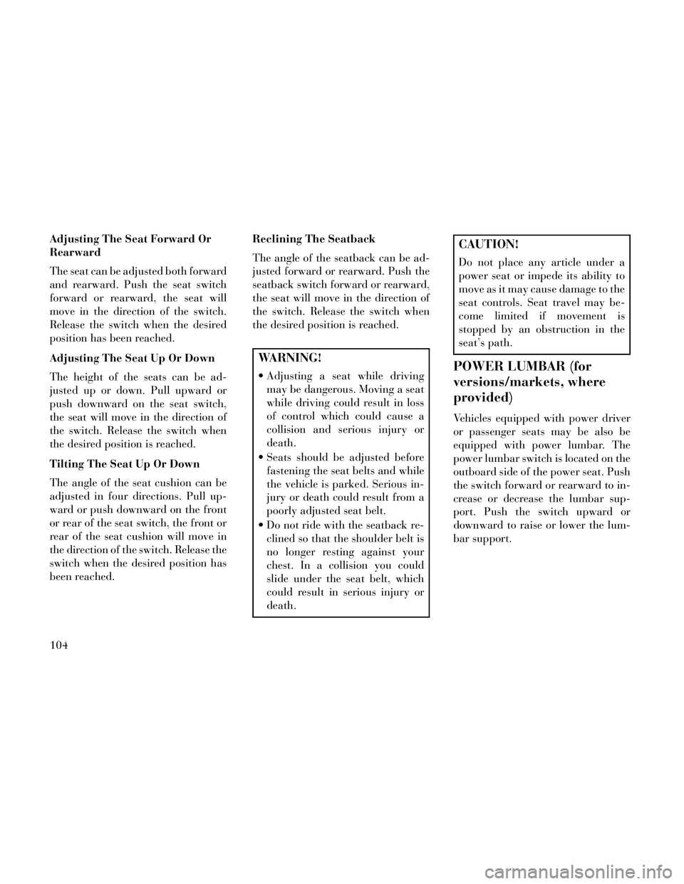
POWER LUMBAR (for
versions/markets, where
provided)
Vehicles equipped with power driver
or passenger seats may be also be
equipped with power lumbar. The
power lumbar switch is located on the
outboard side of the power seat. Push
the switch forward or rearward to in-
crease or decrease the lumbar sup-
port. Push the switch upward or
downward to raise or lower the lum-
bar support.
104
Page 111 of 332
HEATED SEATS (for
versions/markets, where
provided)
On some models, the front and rear
seats may be equipped with heaters in
both the seat cushions and seatbacks.
The front driver and passenger heated
seats are operated using the
Uconnect® System.
WARNING!
Persons who are unable to feelpain to the skin because of ad-
vanced age, chronic illness, dia-
betes, spinal cord injury, medica-
tion, alcohol use, exhaustion or
other physical condition must ex-
ercise care when using the seat
heater. It may cause burns even at
low temperatures, especially if
used for long periods of time.
Do not place anything on the seat or seatback that insulates against
heat, such as a blanket or cush-
ion. This may cause the seat
heater to overheat. Sitting in a
seat that has been overheated
could cause serious burns due to
the increased surface tempera-
ture of the seat.
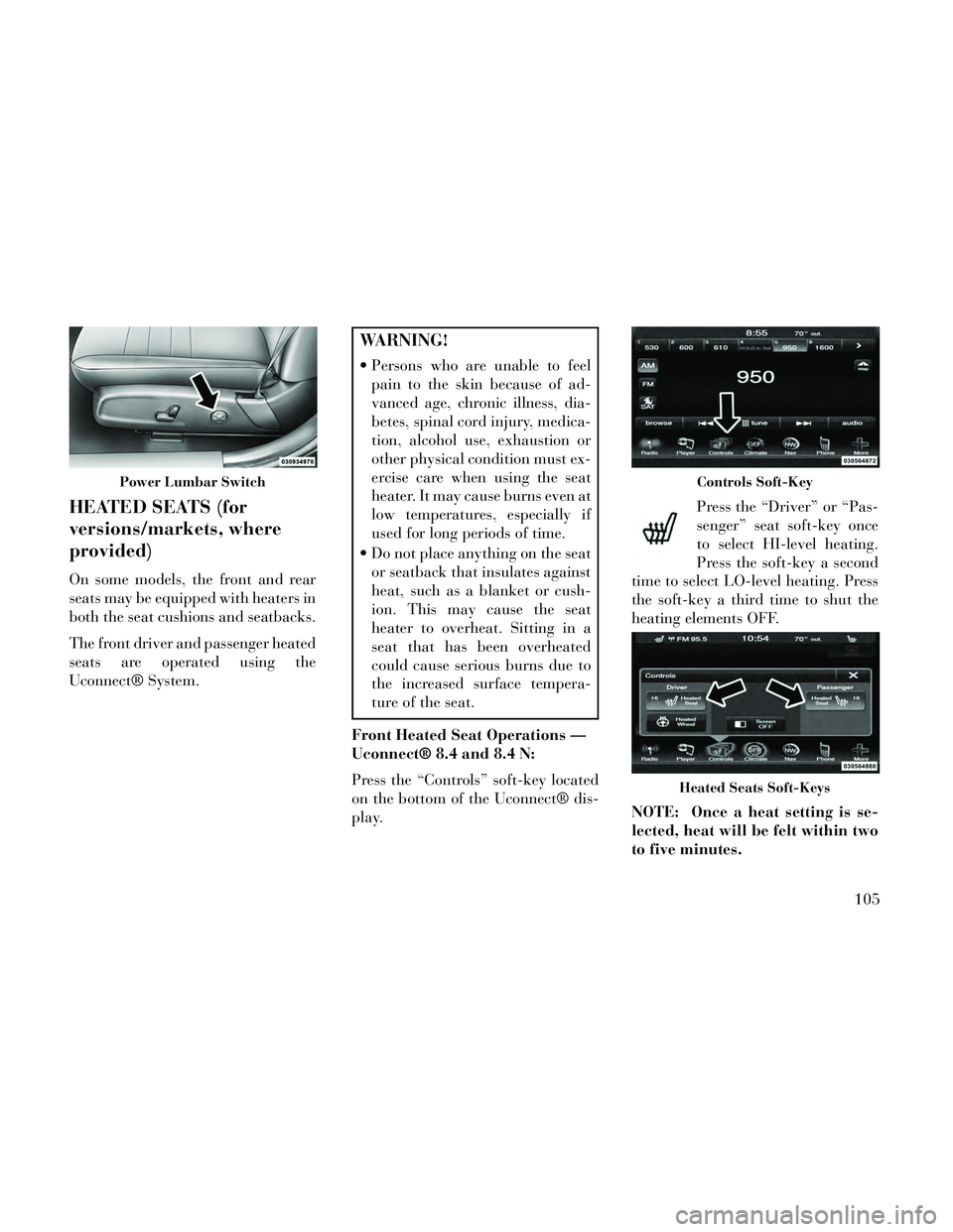
Front Heated Seat Operations —
Uconnect® 8.4 and 8.4 N:
Press the “Controls” soft-key located
on the bottom of the Uconnect® dis-
play. Press the “Driver” or “Pas-
senger” seat soft-key once
to select HI-level heating.
Press the soft-key a second
time to select LO-level heating. Press
the soft-key a third time to shut the
heating elements OFF.
NOTE: Once a heat setting is se-
lected, heat will be felt within two
to five minutes.
Power Lumbar SwitchControls Soft-Key
Heated Seats Soft-Keys
105
Page 113 of 332
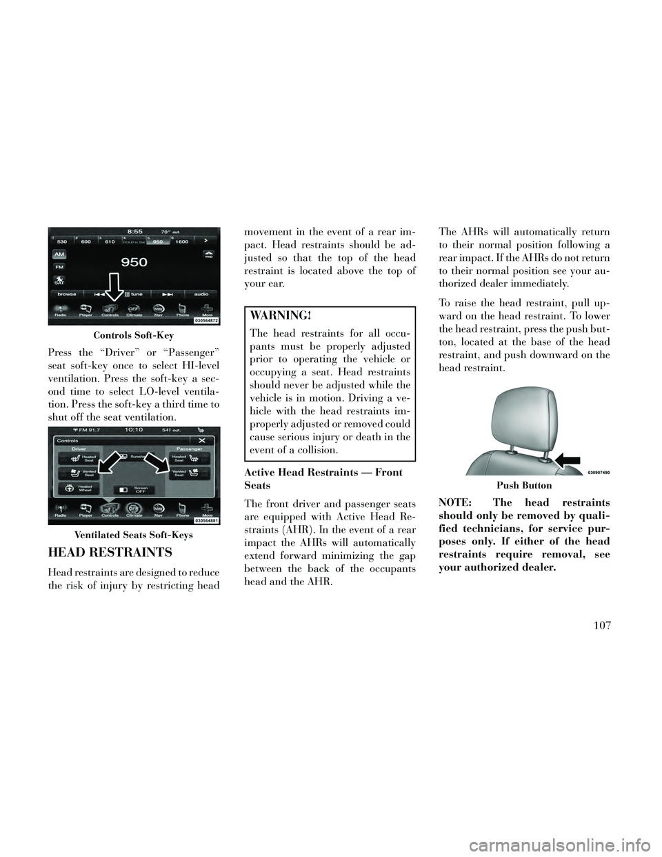
Press the “Driver” or “Passenger”
seat soft-key once to select HI-level
ventilation. Press the soft-key a sec-
ond time to select LO-level ventila-
tion. Press the soft-key a third time to
shut off the seat ventilation.
HEAD RESTRAINTS
Head restraints are designed to reduce
the risk of injury by restricting headmovement in the event of a rear im-
pact. Head restraints should be ad-
justed so that the top of the head
restraint is located above the top of
your ear.
WARNING!
The head restraints for all occu-
pants must be properly adjusted
prior to operating the vehicle or
occupying a seat. Head restraints
should never be adjusted while the
vehicle is in motion. Driving a ve-
hicle with the head restraints im-
properly adjusted or removed could
cause serious injury or death in the
event of a collision.
Active Head Restraints — Front
Seats
The front driver and passenger seats
are equipped with Active Head Re-
straints (AHR). In the event of a rear
impact the AHRs will automatically
extend forward minimizing the gap
between the back of the occupants
head and the AHR. The AHRs will automatically return
to their normal position following a
rear impact. If the AHRs do not return
to their normal position see your au-
thorized dealer immediately.
To raise the head restraint, pull up-
ward on the head restraint. To lower
the head restraint, press the push but-
ton, located at the base of the head
restraint, and push downward on the
head restraint.
NOTE: The head restraints
should only be removed by quali-
fied technicians, for service pur-
poses only. If either of the head
restraints require removal, see
your authorized dealer.Controls Soft-Key
Ventilated Seats Soft-Keys
Push Button
107
Page 114 of 332

WARNING!
Do not place items over the top of
the Active Head Restraint, such as
coats, seat covers or portable DVD
players. These items may interfere
with the operation of the Active
Head Restraint in the event of a
collision and could result in serious
injury or death.
Rear Head Restraints
The center head restraint has two po-
sitions, up or down. When the center
seat is being occupied the head re-
straint should be in the raised posi-
tion. When there are no occupants in
the center seat the head restraint can
be lowered for maximum visibility for
the driver.
To raise the head restraint, pull up-
ward on the head restraint. To lower
the head restraint, press the push but-
ton, located at the base of the head
restraint, and push downward on the
head restraint. NOTE: The outboard head re-
straints are not adjustable. Refer
to “Occupant Restraints” in
“Things To Know Before Starting
Your Vehicle” for tether routing.
FOLDING REAR SEAT
The rear seatbacks can be folded for-
ward to provide an additional storage
area. To fold the rear seatback, pull on
the loops located on the upper seat-
back.
NOTE: These loops can be tucked
away when not in use.
After releasing the seatback, it can be
folded forward.
When the seatback is folded to the
upright position, make sure it is
latched by strongly pulling on the top
of the seatback above the seat strap.
Push ButtonRear Seatback Loop
Folded Rear Seatback
108
Page 115 of 332
WARNING!
Be certain that the seatback issecurely locked into position. If
the seatback is not securely
locked into position, the seat will
not provide the proper stability
for child seats and/or passengers.
An improperly latched seat could
cause serious injury.
The cargo area in the rear of the vehicle (with the rear seatbacks
in the locked-up or folded down
position) should not be used as a
play area by children when the
vehicle is in motion. They could
be seriously injured in a collision.
Children should be seated and us-
ing the proper restraint system.
DRIVER MEMORY SEAT
(for versions/markets,
where provided)
This feature allows the driver to store
up to two different memory profiles
for easy recall through a memory
switch. Each memory profile contains
desired position settings for the driver seat, side mirrors, adjustable pedals
(for versions/markets, where pro-
vided), and power tilt and telescopic
steering column (for versions/
markets, where provided) and a set of
desired radio station presets. Your Re-
mote Keyless Entry (RKE) transmit-
ter can also be programmed to recall
the same positions when the UN-
LOCK button is pressed.
NOTE:
Only one RKE transmitter can
be linked to each of the memory
positions.
Passive Entry door handles can- not be linked to the memory
function. Use either the memory
recall switch or the RKE trans-
mitter (if linked to the memory
feature) to recall memory posi-
tions 1 or 2.
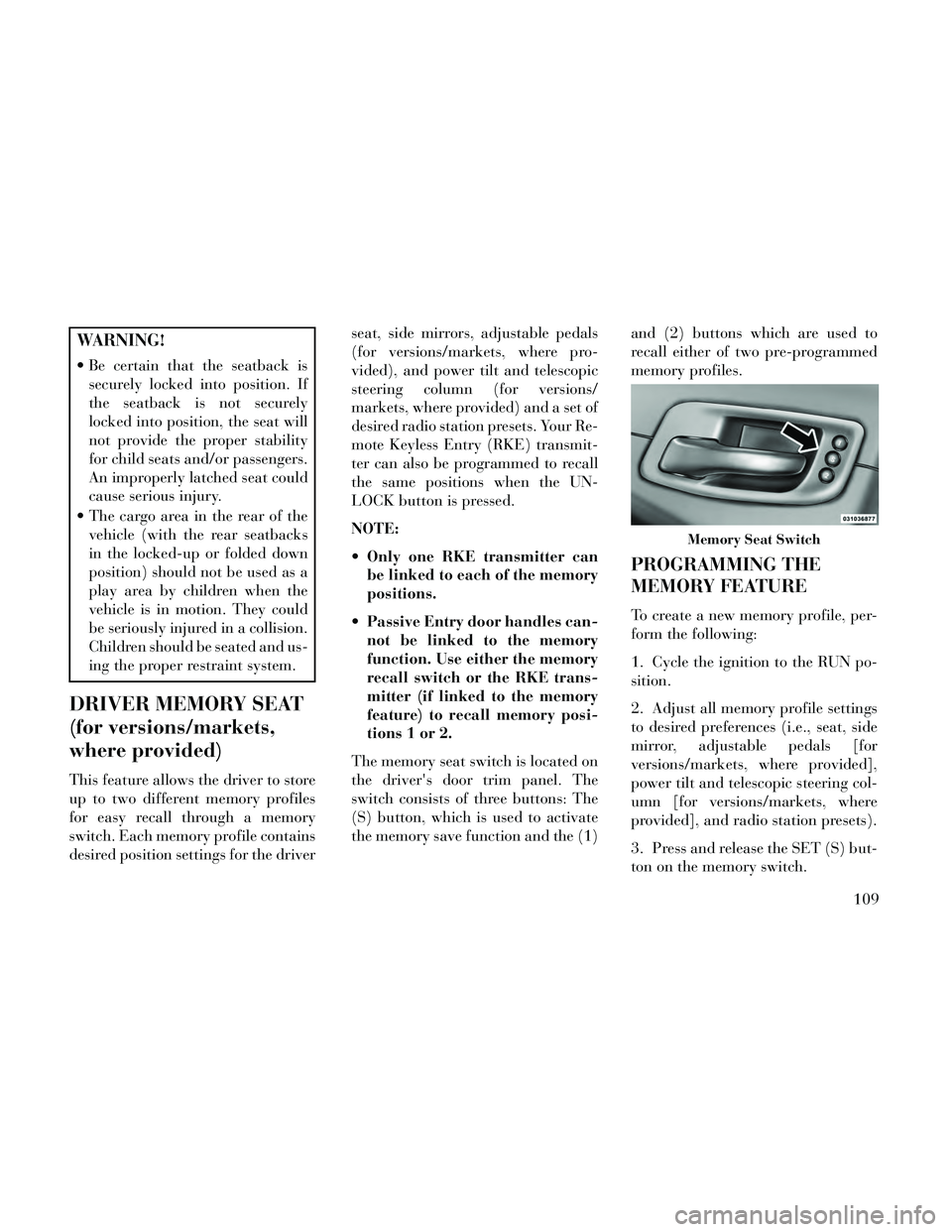
The memory seat switch is located on
the driver's door trim panel. The
switch consists of three buttons: The
(S) button, which is used to activate
the memory save function and the (1) and (2) buttons which are used to
recall either of two pre-programmed
memory profiles.
PROGRAMMING THE
MEMORY FEATURE
To create a new memory profile, per-
form the following:
1. Cycle the ignition to the RUN po-
sition.
2. Adjust all memory profile settings
to desired preferences (i.e., seat, side
mirror, adjustable pedals [for
versions/markets, where provided],
power tilt and telescopic steering col-
umn [for versions/markets, where
provided], and radio station presets).
3. Press and release the SET (S) but-
ton on the memory switch.
Memory Seat Switch
109
Page 118 of 332
NOTE: Your vehicle may be
equipped with an Active Hood Sys-
tem. Refer to “Occupant Re-
straints” in “Things To Know Be-
fore Starting Your Vehicle” for
further information.
CAUTION!
To prevent possible damage, do not
slam the hood to close it. Lower the
hood until it is open approximately
15 cm, and then drop it. This
should secure both latches. Never
drive your vehicle unless the hood is
fully closed, with both latches en-
gaged.
WARNING!
Be sure the hood is fully latched
before driving your vehicle. If the
hood is not fully latched, it could
open when the vehicle is in motion
and block your vision. Failure to
follow this warning could result in
serious injury or death.
LIGHTS
HEADLIGHT SWITCH
The headlight switch is located
on the left side of the instru-
ment panel. This switch con-
trols the operation of the headlights,
parking lights, instrument panel
lights, instrument panel light dim-
ming, interior lights and fog lights.
NOTE: In certain European
countries, the parking light feature
will only operate with the ignition
OFF, or with either the fog lamps or
headlights also ON. Regardless of
ignition switch position, the park-
ing lights will remain ON as long as
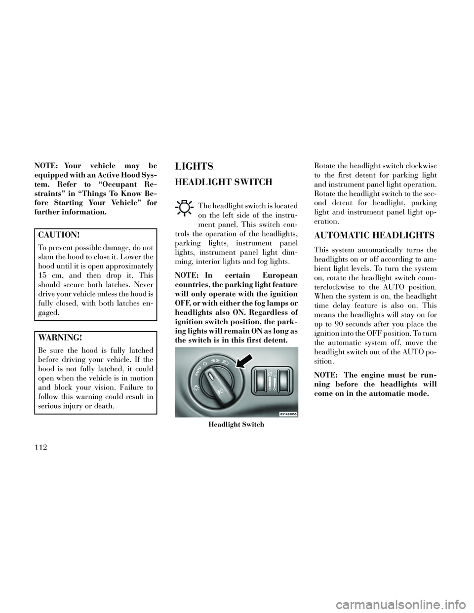
the switch is in this first detent. Rotate the headlight switch clockwise
to the first detent for parking light
and instrument panel light operation.
Rotate the headlight switch to the sec-
ond detent for headlight, parking
light and instrument panel light op-
eration.
AUTOMATIC HEADLIGHTS
This system automatically turns the
headlights on or off according to am-
bient light levels. To turn the system
on, rotate the headlight switch coun-
terclockwise to the AUTO position.
When the system is on, the headlight
time delay feature is also on. This
means the headlights will stay on for
up to 90 seconds after you place the
ignition into the OFF position. To turn
the automatic system off, move the
headlight switch out of the AUTO po-
sition.
NOTE: The engine must be run-
ning before the headlights will
come on in the automatic mode.
Headlight Switch
112
Page 125 of 332

If you activate the washer while the
windshield wiper control is in the de-
lay range, the wipers will operate for
two wipe cycles after releasing the
lever and then resume the intermit-
tent interval previously selected.
If you activate the washer while the
windshield wiper is turned off, the
wipers will operate for three wipe
cycles and then turn off.
WARNING!
Sudden loss of visibility through
the windshield could lead to a col-
lision. You might not see other ve-
hicles or other obstacles. To avoid
sudden icing of the windshield dur-
ing freezing weather, warm the
windshield with the defroster be-
fore and during windshield washer
use.
RAIN SENSING WIPERS
(for versions/markets,
where provided)
This feature senses moisture on the
windshield and automatically acti-
vates the wipers for the driver. Thefeature is especially useful for road
splash or over spray from the wind-
shield washers of the vehicle ahead.
Rotate the end of the multifunction
lever to one of four settings to activate
this feature.
The sensitivity of the system can be
adjusted with the multifunction lever.
Wiper delay position 1 is the least
sensitive, and wiper delay position 4 is
the most sensitive. Setting 3 should be
used for normal rain conditions. Set-
tings 1 and 2 can be used if the driver
desires less wiper sensitivity. Settings
4 can be used if the driver desires
more sensitivity. The rain sense wip-
ers will automatically change between
an intermittent wipe, slow wipe and a
fast wipe depending on the amount of
moisture that is sensed on the wind-
shield. Place the wiper switch in the
OFF position when not using the sys-
tem.
The Rain Sensing feature can be
turned on and off using the
Uconnect® System, refer to
“Uconnect® Settings” in “Under-
standing Your Instrument Panel” for
further information.
NOTE:
The Rain Sensing feature will
not operate when the wiper
speed is in the low or high posi-
tion.
The Rain Sensing feature may not function properly when ice
or dried salt water is present on
the windshield.
The use of products containing wax or silicone may reduce rain
sensor performance.
The Rain Sensing system has protec-
tive features for the wiper blades and
arms. It will not operate under the
following conditions:
Low Temperature Wipe Inhibit
— The Rain Sensing feature will
not operate when the ignition is
placed in the RUN position, the ve-
hicle is stationary and the outside
temperature is below 0°C, unless
the wiper control on the multifunc-
tion lever is moved, the vehicle
speed becomes greater than 0 km/h
or the outside temperature rises
above freezing.
119
Page 126 of 332

Neutral Wipe Inhibit — The Rain
Sensing feature will not operate
when the ignition is placed in the
RUN position, the transmission
shift lever is in the NEUTRAL po-
sition and the vehicle speed is less
than 8 km/h, unless the wiper con-
trol on the multifunction lever is
moved or the shift lever is moved
out of the NEUTRAL position.
HEADLIGHT WASHERS
The multifunction lever operates the
headlight washers when the ignition
switch is in the ON position and the
headlights are turned on. The multi-
function lever is located on the left
side of the steering column.
To use the headlight washers, push
the multifunction lever inward (to-
ward the steering column) and release
it. The headlight washers will spray a
timed high-pressure spray of washer
fluid onto each headlight lens. In ad-
dition, the windshield washers will
spray the windshield and the wind-
shield wipers will cycle. NOTE: After turning the ignition
switch and headlights ON, the
headlight washers will operate on
the first spray of the windshield
washer and then every eleventh
spray after that.
TILT/TELESCOPING
STEERING COLUMN
This feature allows you to tilt the
steering column upward or down-
ward. It also allows you to lengthen or
shorten the steering column. The tilt/
telescoping control handle is located
below the steering wheel at the end of
the steering column.
To unlock the steering column, pull
the control handle outward. To tilt the
steering column, move the steeringwheel upward or downward as de-
sired. To lengthen or shorten the
steering column, pull the steering
wheel outward or push it inward as
desired. To lock the steering column
in position, push the control handle
inward until fully engaged.
WARNING!
Do not adjust the steering column
while driving. Adjusting the steer-
ing column while driving or driving
with the steering column unlocked,
could cause the driver to lose con-
trol of the vehicle. Failure to follow
this warning may result in serious
injury or death.
POWER TILT/
TELESCOPING
STEERING COLUMN (for
versions/markets, where
provided)
This feature allows you to tilt the
steering column upward or down-
ward. It also allows you to lengthen or
shorten the steering column. TheTilt/Telescoping Control Handle
120