remote control Lancia Thesis 2006 Owner handbook (in English)
[x] Cancel search | Manufacturer: LANCIA, Model Year: 2006, Model line: Thesis, Model: Lancia Thesis 2006Pages: 386, PDF Size: 8.69 MB
Page 53 of 386
52
The other recognition system set-
tings that can be enabled/disabled
are:
– automatic locking of doors and
boot.
As regards the setting of the recog-
nition system customizations, refer
to the CONNECT supplement.
FAILURE INDICATION
The presence of anomalies in the
Keyless System is indicated by the
lighting of symbol Yon the instru-
ment display, together with the mes-
sage “VEHICLE PROTECTION
SYSTEM FAULT”.
IMPORTANT In case of fault, con-
tact your Lancia Dealership.
Before and during auto-
matic actuation of the
window regulators and
sunroof, always make sure that
the passengers and the persons
standing near the car are not
exposed to the risk of injures that
may be caused either by the mov-
ing windows and sunroof or by
objects dragged or hit by the
same. To actuate central opening of the
windows and sunroof, keep the
remote control button B(fig. 25)
depressed for more than 2 seconds
after opening the doors: both the win-
dow regulators and the sunroof will be
actuated until they are fully opened or
until the button is released.
This function can be used to aerate
the passenger’s compartment before
getting into the car parked in the sun.
IMPORTANT Do not lay the CID
device outside the car on the sunroof,
to avoid a fake identification of the
CID itself as if inside the car. It is rec-
ommend to carry about with you the
CID device (e.g. into a pocket). SYSTEM SETTINGS
The CONNECT enables to cus-
tomize certain functions of the
Keyless System recognition system,
through the settings that can be
selected on the CONNECT display.
The “central unlock” and “driver’s
door unlock” functions of the central
locking can be set also for the
Keyless System and operate as fol-
lows:
– central unlock: all the car doors
are unlocked simultaneously and
access is possible through every door
– driver’s door unlock: access is
possible through the driver’s door
whereas the other doors remain
locked, thus preventing un-autho-
rized persons from getting into the
car. In this case, the led on the dri-
ver’s door panel lights up (green
colour) whereas the leds on the other
doors remain off.
When “unlocking driver’s door” is
set, it is anyhow possible to unlock all
the doors, to enable access to passen-
gers, by pushing button B(fig. 18) on
CID device or, after opening the dri-
ver’s door, by pushing the central
unlock button existing on the door
panel.
Page 56 of 386
55
To unlock, turn the key clockwise
1; to lock, turn the key counter-
clockwise 2.
When the doors are released by
means of the remote control, the
alarm system and the deadlock
device (described below) are also
switched off.
IMPORTANTThe electronic
alarm will not be switched off if the
door is unlocked by the key in the
lock.
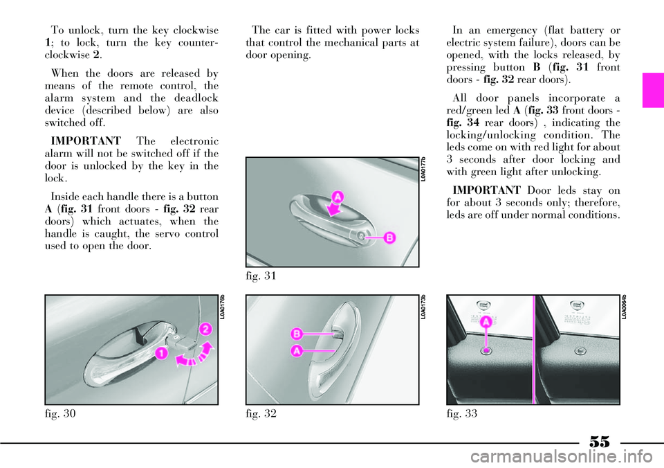
Inside each handle there is a button
A(fig. 31 front doors -fig. 32 rear
doors) which actuates, when the
handle is caught, the servo control
used to open the door.The car is fitted with power locks
that control the mechanical parts at
door opening.
fig. 30
L0A0176b
fig. 32
L0A0173b
fig. 31
L0A0177b
In an emergency (flat battery or
electric system failure), doors can be
opened, with the locks released, by
pressing button B(fig. 31 front
doors -fig. 32 rear doors).
All door panels incorporate a
red/green led A(fig. 33 front doors -
fig. 34 rear doors) , indicating the
locking/unlocking condition. The
leds come on with red light for about
3 seconds after door locking and
with green light after unlocking.
IMPORTANTDoor leds stay on
for about 3 seconds only; therefore,
leds are off under normal conditions.
fig. 33
L0A0064b
Page 57 of 386

56
Deadlock device
The deadlock device enables to dis-
connect mechanically the internal
door handles; in this case, doors can-
not be opened from the inside by
acting on the handles after breaking
the glass (improving protection
against theft).
The device can be switched on by
pressing the remote control button B
(fig. 29) again within 1 second after
closing the doors: active function
will be indicated by a beep and 2
further blinks of the direction indi-
cators.
The device activates only if all the
doors are properly closed.
When the deadlock device is
switched on, the door panel leds will
flash twice with red light.
After activating the dead
lock device it will be
impossible to get out of
the passenger compartment: for
this reason this device must be
activated only after making sure
that the passenger compartment
is empty.The front door leds are also used as
deterrent leds for the alarm system;
as a consequence, they will flash
when the alarm system is on or the
doors are locked.
The CONNECT enables to set the
central locking of all the doors or
only the driver’s door.
In the former case, all the car doors
are unlocked simultaneously and
access is possible through any door.
In the second case, access is possible
only through the driver’s door,
whereas the other doors are locked,
thus preventing un-authorized per-
sons from getting into the car.In this case, the driver’s door led
comes on with green light, whereas
the leds on the other doors will
remain off.
When only the driver’s door is
unlocked, after opening the driver’s
door, also the other doors can be
unlocked by pressing the central
unlocking button B(fig. 35) so as to
enable passengers getting into the
car.
IMPORTANTButtons Band C
(fig. 35) are disabled when the doors
are locked from the outside.
If, when the doors are closed from
the outside, one or more doors
and/or the boot are not closed cor-
rectly, the direction indicators will
flash rapidly for a few seconds.
fig. 34
L0A0063b
fig. 35
L0A0051b
Page 58 of 386

57
OPENING/CLOSING FROM
THE INSIDE
To open the door even when the
lock is locked, pull handle A(fig. 35
front doors -fig. 36 rear doors) set in
the upper part of the panel.
Next to each door handle are two
buttons that actuate lock
locking/unlocking:
– B button for unlocking;
– Cbutton for locking.
The red/green leds A(fig. 33 front
doors –fig. 34 rear doors) indicate
the locking/unlocking condition.
The leds come on with red light for
about 3 seconds after door locking
and with green light after unlocking.
By pulling the internal handle of
the driver’s door, all the doors or
only the driver’s door will be simul-
taneously unlocked, depending on
the setting selected on the CON-
NECT. By pulling the internal han-
dle of any other door, all the doors
are simultaneously unlocked.
fig. 36
L0A0052b
With the dead lock
device on, pressing the
external handle button of
one of the doors while unlocking
the doors by the remote control
could cause the disconnection of
the internal handle of the
involved door thus making
impossible to open that door
from the inside. To restore regu-
lar operation, just press the
remote control central door
unlocking button or button B (fig.
36) on the door panel.A led is located near each door
handle to make it easy to find the
handle in the dark. The leds light up
for about 2 minutes after turning the
ignition key to STOPor until a door
is opened.
Door open indication
The driver is informed that one or
several doors are not closed correct-
ly by the lighting of the correspond-
ing symbols on the instrument dis-
play, together with the messages
“DOOR OPEN” or “DOORS
OPEN”.
Page 60 of 386
59
AUTOCLOSE FUNCTION
(AUTOMATIC LOCKING
WITH KEYLESS SYSTEM
RECOGNITION SYSTEM)
On versions equipped with Keyless
System, the “Autoclose” function
can be actuated/deactivated through
the CONNECT settings. This func-
tion makes it possible to automati-
cally lock the boot and doors when
the CID device is taken away from
the car.
When leaving the car, if one or
more doors are not closed correctly,
the car will remain open and a fur-
ther beep will sound to indicate that
the locks have not been locked.
The “Autoclose” functions actuates
neither the alarm system nor the
door deadlock device (refer to the
contents of the relevant paragraph).
In any case, these functions can be
actuated by means of the remote
control.LOCK RELEASE IN CASE OF
ACCIDENT
In case of collision with actuation
of the inertia switch, the door locks
are automatically released to allows
rescuers to get access to the passen-
ger compartment.In any case, door open-
ing from the outside
depends on the door con-
ditions after the collision:
deformed doors cannot very often
be opened even if the lock is
released. In such a case, try to
open the other doors.
INITIALISING THE DOOR
LOCKING CONTROL UNIT
Whenever the battery is electrically
connected again or it is reloaded
after being completely flat or after
replacing one of the protection fuses,
to restore the correct operation of
the door locking, of air conditioning
and of ESP system, it is necessary to
perform the initialisation operations
contained in the paragraph “If bat-
tery is to be disconnected” in the
chapter “In an emergency”. The external mechanical
connections are active
only when the doors are
unlocked.
In the event that the driver has
actuated central locking from the
inside and, after a collision, the
inertia switch has not actuated
the automatic door unlocking
function due to the loss of or
damage to the battery, access to
the passenger compartment will
not be possible from the outside.
Page 68 of 386
67
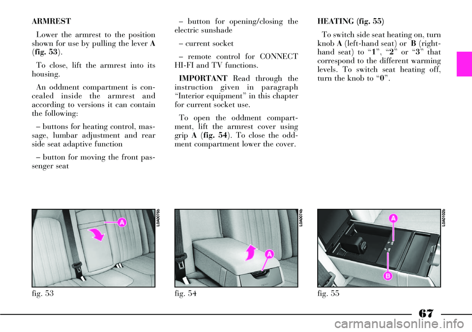
ARMREST
Lower the armrest to the position
shown for use by pulling the lever A
(fig. 53).
To close, lift the armrest into its
housing.
An oddment compartment is con-
cealed inside the armrest and
according to versions it can contain
the following:
– buttons for heating control, mas-
sage, lumbar adjustment and rear
side seat adaptive function
– button for moving the front pas-
senger seat– button for opening/closing the
electric sunshade
– current socket
– remote control for CONNECT
HI-FI and TV functions.
IMPORTANTRead through the
instruction given in paragraph
“Interior equipment” in this chapter
for current socket use.
To open the oddment compart-
ment, lift the armrest cover using
grip A(fig. 54). To close the odd-
ment compartment lower the cover. HEATING (fig. 55)
To switch side seat heating on, turn
knob A(left-hand seat) or B(right-
hand seat) to “1”, “2” or “3” that
correspond to the different warming
levels. To switch seat heating off,
turn the knob to “0”.
fig. 53
L0A0076b
fig. 54
L0A0074b
fig. 55
L0A0102b
Page 76 of 386
75
Pressing briefly the button the win-
dow “jerks”, whereas a prolonged
pressing makes the window opening
or closing in “automatic and continu-
ous” mode. When pressing again the
button the window stops in the
required position.
Rear controls
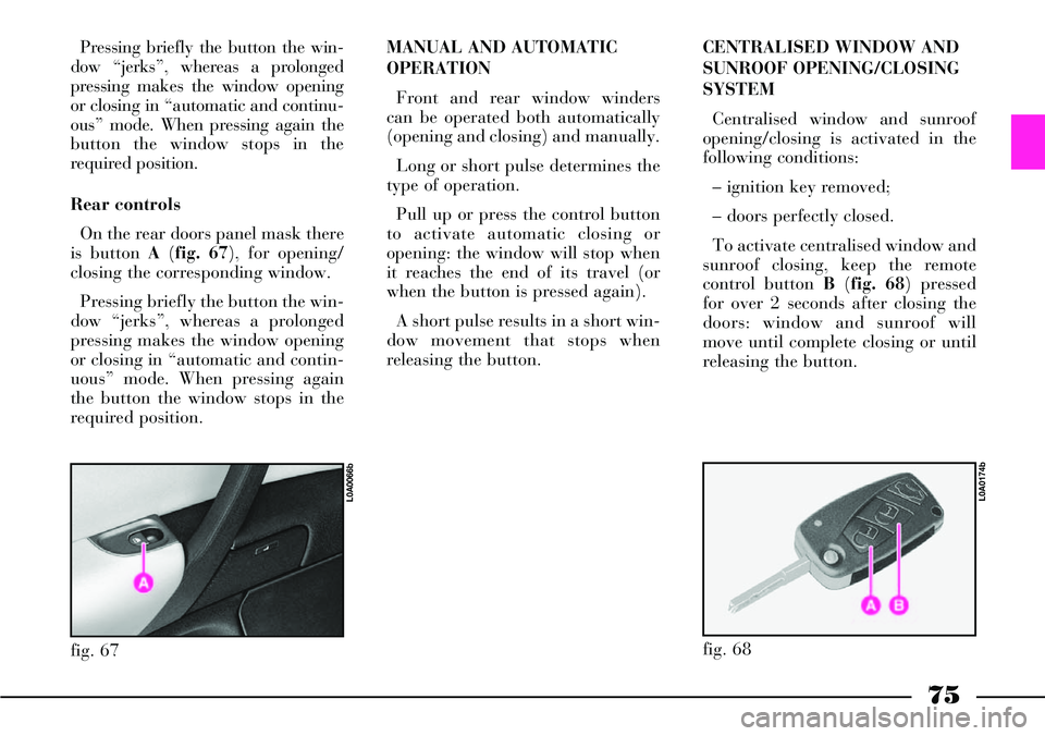
On the rear doors panel mask there
is button A (fig. 67), for opening/
closing the corresponding window.
Pressing briefly the button the win-
dow “jerks”, whereas a prolonged
pressing makes the window opening
or closing in “automatic and contin-
uous” mode. When pressing again
the button the window stops in the
required position.MANUAL AND AUTOMATIC
OPERATION
Front and rear window winders
can be operated both automatically
(opening and closing) and manually.
Long or short pulse determines the
type of operation.
Pull up or press the control button
to activate automatic closing or
opening: the window will stop when
it reaches the end of its travel (or
when the button is pressed again).
A short pulse results in a short win-
dow movement that stops when
releasing the button.CENTRALISED WINDOW AND
SUNROOF OPENING/CLOSING
SYSTEM
Centralised window and sunroof
opening/closing is activated in the
following conditions:
– ignition key removed;
– doors perfectly closed.
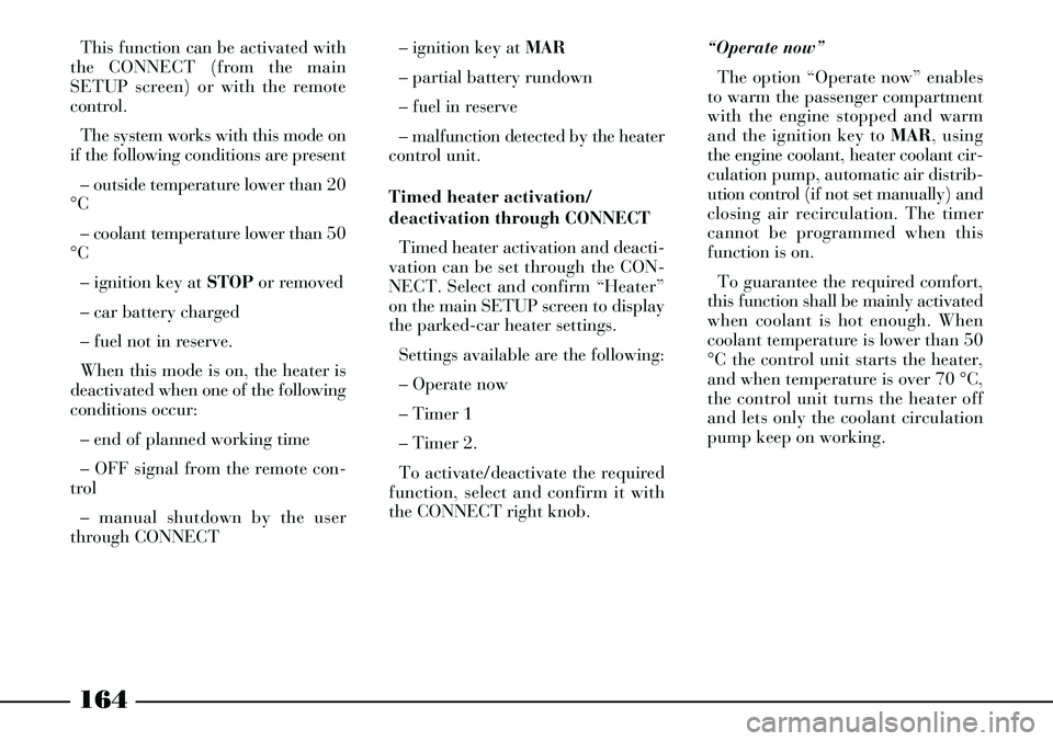
To activate centralised window and
sunroof closing, keep the remote
control button B(fig. 68) pressed
for over 2 seconds after closing the
doors: window and sunroof will
move until complete closing or until
releasing the button.
fig. 67
L0A0066b
fig. 68
L0A0174b
Page 123 of 386

122
Follow me home device
Warning light/symbol
-
Instrument dimmer
Warning light/symbol
x
Meaning of the message
Indicates the set lighting
level (for instrument panel,
display and buttons)
Meaning of the message
Indicates that the “Follow me
home” device is on, external
lights will therefore stay on
for the set time Remarks
–
Remarks
Minimum: 30 seconds,
maximum: 210 seconds, 30
seconds intervals
Steering wheel lock
Warning light/symbol
-
Message
FOLLOW ME
XXs Message
STEERING LOCKED WHEN
DOORS CLOSEDMeaning of the message
Steering will be locked when
locking the doors
with the remote controlRemarks
– Message
DIMMER
INSTRUMENT
Page 165 of 386
164
This function can be activated with
the CONNECT (from the main
SETUP screen) or with the remote
control.
The system works with this mode on
if the following conditions are present
– outside temperature lower than 20
°C
– coolant temperature lower than 50
°C
– ignition key at STOPor removed
– car battery charged
– fuel not in reserve.
When this mode is on, the heater is
deactivated when one of the following
conditions occur:
– end of planned working time
– OFF signal from the remote con-
trol
– manual shutdown by the user
through CONNECT– ignition key at MAR
– partial battery rundown
– fuel in reserve
– malfunction detected by the heater
control unit.
Timed heater activation/
deactivation through CONNECT
Timed heater activation and deacti-
vation can be set through the CON-
NECT. Select and confirm “Heater”
on the main SETUP screen to display
the parked-car heater settings.
Settings available are the following:
– Operate now
– Timer 1
– Timer 2.
To activate/deactivate the required
function, select and confirm it with
the CONNECT right knob.“Operate now”
The option “Operate now” enables
to warm the passenger compartment
with the engine stopped and warm
and the ignition key to MAR, using
the engine coolant, heater coolant cir-
culation pump, automatic air distrib-
ution control (if not set manually) and
closing air recirculation. The timer
cannot be programmed when this
function is on.
To guarantee the required comfort,
this function shall be mainly activated
when coolant is hot enough. When
coolant temperature is lower than 50
°C the control unit starts the heater,
and when temperature is over 70 °C,
the control unit turns the heater off
and lets only the coolant circulation
pump keep on working.
Page 167 of 386

166
– stationary: with the “programma-
ble heater” mode controlled by the
timer, the system conditions are con-
trolled by CONNECT.
The timer is automatically deacti-
vated if:
– the “programmable heater” mode
function is stopped by CONNECT if,
at the timer start, the “programmable
heater” mode is activated with the re-
mote control
– if the user manually activates the
heater during the timer operation
– if the timer is activated within 3
minutes after the previous heater
shutdown
– if the user manually deactivates
the timer– if the fuel level in the tank is low
when the timer is activated. This con-
dition is indicated with a message
coming from the system and the user
must confirm activation. If the user
does not confirm activation, the timer
is deactivated. The fuel level is indi-
cated by the CONNECT; if this infor-
mation is not available, it is taken into
consideration the last record before
stopping the engine
– if the timer is activated when the
heater operated by the remote control
is activated.
IMPORTANTIf the heater is in
prompt operating mode, the timer is
automatically stopped at the moment
of activation. Parameters set with the
timer are stored in the memory. If the
timer has been deactivated or
stopped, it should be manually reac-
tivated by the user.HEATER ACTIVATION/
DEACTIVATION WITH THE
REMOTE CONTROL (fig. 123)
Activation/deactivation of the heater
can be operated with remote control
A.
The activation signal is issued by the
remote control with a range of around
600 meters and picked up by a spe-
cific antenna placed on the car, then
it is transmitted to the supplementary
heater receiver and sent to CON-
NECT.
IMPORTANTThe maximum re-
mote control range is reached on open
land, while it is reduced in the pres-
ence of buildings.
fig. 123
L0A0263b