display Lancia Thesis 2006 Owner handbook (in English)
[x] Cancel search | Manufacturer: LANCIA, Model Year: 2006, Model line: Thesis, Model: Lancia Thesis 2006Pages: 386, PDF Size: 8.69 MB
Page 127 of 386

126
Glow plugs (JTD versions)
Warning light/symbol
m
èm
Message
–
PLUG PREHEATING
FAULT
GO TO DEALERMeaning of the message
Symbol is displayed
when glow plugs
are working. Symbol goes off
when glow plugs reach
the preset temperature.
When outside temperature is high
symbol displaying can be unper-
ceivable
Plug preheating system
faultRemarks / Action
Start engine
as soon as symbol
goes off
Contact a Lancia
Dealership
Fuel level
Warning light/symbol
K
Message
REFUEL Meaning of the message
Low fuel in the tank.
This message is displayed
when about 10 litres
fuel are left in the tank Remarks
Top up fuel
as soon as possible
IMPORTANTDo not travel with
the fuel tank almost empty: the
gaps in fuel delivery could damage
the catalyst
Page 128 of 386

Action
IMPORTANTIf the ¬warning light
does not turn on when turning the ig-
nition key to MARor if it stays on
when travelling, (together with mes-
sage on display) this could indicate a
failure in safety retaining systems; un-
der this condition air bags or preten-
sioners could not trigger in the event of
collision or, in a restricted number of
cases, they could trigger accidentally.
Stop the car and contact Lancia Deal-
ershipto have the system checked im-
mediately.
127
Outside temperature (ice hazard)
Warning light/symbol
❄
Message
WARNING ICE HAZARDMeaning of the message
Outside temperature is low
and there could be ice on the roadRemarks
Under certain conditions
(bridges, overbridges,
curves or road sections in
the shade, etc.) the air temperature
at ground level can be lower than
that at sensor level and therefore
there can be ice on the road
although this warning message is
not displayed
Message
AIRBAG SYSTEM
FAULT
AIRBAG SYSTEM
FAULT
SWITCH OFF ENGINE,
DO NOT PROCEEDMeaning of the message
Airbag system
failure
Airbag system
failure
Airbag
Warning light/symbol
¬
Page 130 of 386

ASR SYSTEM (wheel antiskid system)
Warning light/symbol
V
Message
ASR OFF
ASR ON
SYSTEM
UNAVAILABLEMeaning of the message
System has been deactivated
manually
System has been activated
manually
System setting in progressAction
–
–
–
EBD SYSTEM (electronic brakeforce distributor)
Warning light/symbol
x>
Message
EBD SYSTEM FAULT
SWITCH OFF ENGINE,
DO NOT PROCEED
SYSTEM
UNAVAILABLEMeaning of the message
EBD system failure
System setting in progressAction
Stop the car and contact a
Lancia Dealership
The car is fitted with an
electronic brakeforce
distributor (EBD). The
turning on at the same time of
the
xand >warning lights on
the instrument panel together
with message “EBD SYSTEM
FAULT” on the multifunction
display, with engine running,
indicates and EBD system fail-
ure; in this case heavy braking
may cause the rear wheel lock
before time, with the possibility
of skidding.
–
129
Page 133 of 386
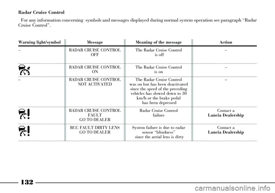
132
Warning light/symbol
–
ú
–
à
à
Message
RADAR CRUISE CONTROL
OFF
RADAR CRUISE CONTROL
ON
RADAR CRUISE CONTROL
NOT ACTIVATED
RADAR CRUISE CONTROL
FAULT
GO TO DEALER
RCC FAULT DIRTY LENS
GO TO DEALERMeaning of the message
The Radar Cruise Control
is off
The Radar Cruise Control
is on
The Radar Cruise Control
was on but has been deactivated
since the speed of the preceding
vehicles has slowed down to 30
km/h or the brake pedal
has been depressed
Radar Cruise Control
failure
System failure is due to radar
sensor “blindness”
since the aerial lens is dirtyAction
–
–
–
Contact a
Lancia Dealership
Contact a
Lancia Dealership
Radar Cruise Control
For any information concerning symbols and messages displayed during normal system operation see paragraph “Radar
Cruise Control”.
Page 142 of 386
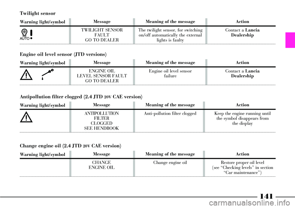
141
Twilight sensor
Warning light/symbol
1
Message
TWILIGHT SENSOR
FAULT
GO TO DEALERMeaning of the message
The twilight sensor, for switching
on/off automatically the external
lights is faultyAction
Contact a Lancia
Dealership
Engine oil level sensor (JTD versions)
Warning light/symbol
èk
Message
ENGINE OIL
LEVEL SENSOR FAULT
GO TO DEALERMeaning of the message
Engine oil level sensor
failureAction
Contact a Lancia
Dealership
Message
ANTIPOLLUTION
FILTER
CLOGGED
SEE HENDBOOK
Meaning of the message
Anti-pollution filter cloggedAction
Keep the engine running until
the symbol disappears from
the display
Antipollution filter clogged (2.4 JTD 20VCAE version)
Warning light/symbol
è
Message
CHANGE
ENGINE OILMeaning of the message
Change engine oilAction
Restore proper oil level
(see “Checking levels” in section
“Car maintenance”)
Change engine oil (2.4 JTD 20VCAE version)
Warning light/symbol
Page 150 of 386
149
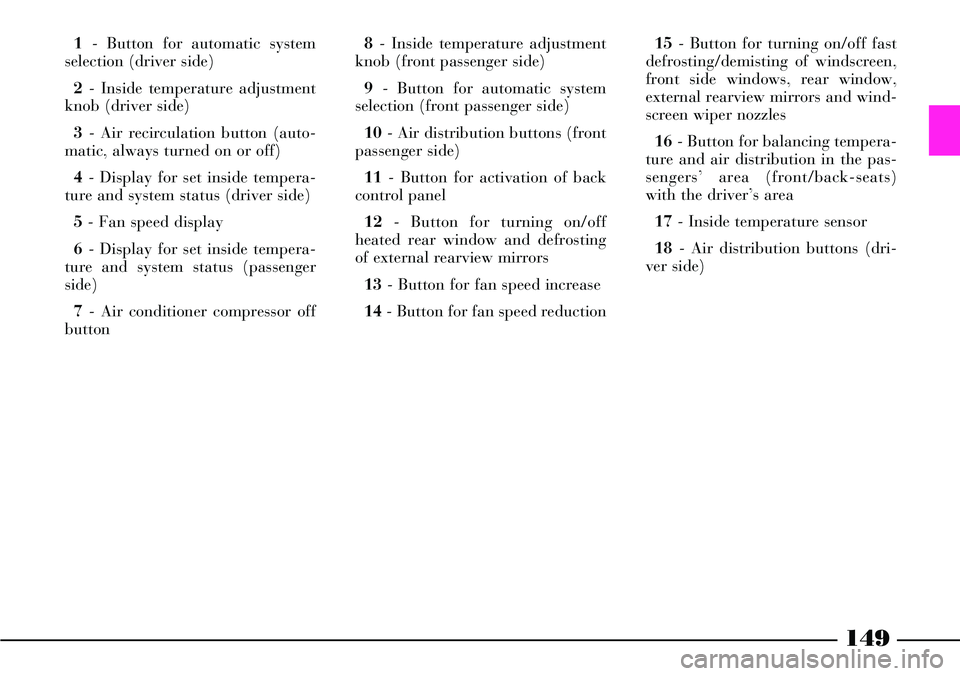
1- Button for automatic system
selection (driver side)
2- Inside temperature adjustment
knob (driver side)
3- Air recirculation button (auto-
matic, always turned on or off)
4- Display for set inside tempera-
ture and system status (driver side)
5- Fan speed display
6- Display for set inside tempera-
ture and system status (passenger
side)
7- Air conditioner compressor off
button 8- Inside temperature adjustment
knob (front passenger side)
9- Button for automatic system
selection (front passenger side)
10- Air distribution buttons (front
passenger side)
11- Button for activation of back
control panel
12- Button for turning on/off
heated rear window and defrosting
of external rearview mirrors
13- Button for fan speed increase
14- Button for fan speed reduction15- Button for turning on/off fast
defrosting/demisting of windscreen,
front side windows, rear window,
external rearview mirrors and wind-
screen wiper nozzles
16- Button for balancing tempera-
ture and air distribution in the pas-
sengers’ area (front/back-seats)
with the driver’s area
17- Inside temperature sensor
18- Air distribution buttons (dri-
ver side)
Page 151 of 386
150
The cooling system uses
coolant “R134a” refriger-
ating fluid that meets cur-
rent regulations and does not
pollute the environment if it acci-
dentally leaks. Under no circum-
stances should other fluids be
used which are incompatible
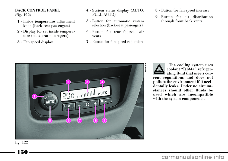
with the system components. BACK CONTROL PANEL
(fig. 122)
1- Inside temperature adjustment
knob (back-seat passengers)
2- Display for set inside tempera-
ture (back-seat passengers)
3- Fan speed display 4- System status display (AUTO,
FULL AUTO)
5- Button for automatic system
selection (back-seat passengers)
6- Button for rear footwell air
vents
7- Button for fan speed reduction8- Button for fan speed increase
9- Button for air distribution
through front back vents
fig. 122
L0A0101b
Page 152 of 386
151
HOW TO USE THE CLIMATE
CONTROL SYSTEM
The system can be switched on in
various ways. We recommend start-
ing by pressing the AUTObutton
and setting the required tempera-
tures on the display.
Since the system controls three
areas of the passenger compartment,
the driver and the front/back pas-
sengers can select different tempera-
ture values, with a maximum differ-
ence accepted by the system of 7 °
C.
In this way, the system will start
working fully automatically to reach
the required temperature as soon as
possible. It will maintain the tem-
perature by adjusting the amount
and distribution pattern of the air let
into the passenger compartment and
manage the recirculation function
and the climate control system com-
pressor.When the system is working auto-
matically, the only possible manual
functions are:
– MONO, to align air temperature
and distribution on the passenger
side or in the back-seat passengers’
area with that on the driver side;
– REAR, to activate the back con-
trol panel;
– √, to switch off the compressor:
in these conditions the system works
only as a heater;
– air recirculation, to keep recircu-
lation always turned on or off;
–-, for faster defrosting/demist-
ing the front windows, rear window,
external rearview mirrors and wind-
screen wiper nozzles;
– (,for defrosting/demisting the
heated rear window and external
rearview mirrors.The temperature, air distribution
and fan speed settings can be
changed at any time during auto-
matic system operation. The system
will automatically adjust to the new
request. When the system is fully
working in automatic mode (FULL
AUTO), if air distribution and/or
flow is changed, definition FULL
disappears. In this way functions
pass from the automatic mode to the
manual mode, until button AUTOis
pressed again. There is only one fan
speed for all the passenger compart-
ment areas and it can be changed
also by operating back controls,
when activated.
With one or more functions manu-
ally on, the air temperature let into
the passenger compartment is auto-
matically managed by the system
unless the climate control compres-
sor is off. In this condition, in fact,
the air inlet into the passenger com-
partment cannot have a lower tem-
perature than that of the external
air.
Page 153 of 386
152
CONTROLS
Knobs for adjusting air tempera-
ture (2, 8 fig. 121 - 1 fig. 122)
Turn the knobs towards the right
or towards the left to raise or lower
the air temperature required respec-
tively in the front left-hand area
(knob 2 fig. 121) and in the front
right-hand area (knob 8 fig. 121) or
back area (knob 1 fig. 122) of the
passenger compartment.
Since the system controls three
areas of the passenger compartment,
the driver and the front/back-seat
passengers can select different tem-
perature values with a maximum
difference accepted by the system of
7 °
C.
Temperature control in the front
passenger area and in the back pas-
senger area is alternated; when the
button led REARis off, control of
front passenger side is on, but when
button REARis pressed (button led
on) the back control panel is activat-
ed. The set temperatures are shown on
the displays set near the respective
knobs.
Press button 16(MONO - fig. 121)
to automatically align the
(front/back) passenger temperature
to the temperature on driver’s side.
Consequently the temperature in the
two areas can be set simply by turn-
ing the knob on the driver side 2
(fig. 121). This function is provided
to facilitate adjusting the temperature
in the passenger compartment when
only the driver is present. The sepa-
rate operation of the set temperatures
and air distribution is automatically
reset when knobs 8 (fig. 121) or 1
(fig. 122) are turned or button 16
(MONO - fig. 121) is pressed again,
when the button led is turned on.
Turn the knobs fully to the right or
to the left to the end positions HIor
LO, to obtain maximum heating or
cooling, respectively:– HIfunction (maximum heating):
this is switched on by turning the
temperature knob to the right
beyond the maximum value (32 °C).
It can be independently switched on
from driver’s side or from
(front/back) passenger’s side or
from both sides (also by selecting the
MONOfunction).
This function can be switched on to
speed up heating in the passenger
compartment by exploiting the sys-
tem potential to the maximum. The
function employs the maximum
coolant temperature while the air
distribution and fan speed are set by
the system according to environ-
mental conditions. In particular, if
the coolant temperature is not suffi-
cient, the function does not switch
the fan on at top speed to limit let-
ting into air which is not adequately
warm.
All the manually settings can be
adjusted when the function is on.
Page 154 of 386

153
To switch this function off, turn
the temperature knob to the left and
set the required temperature.
– LOfunction (maximum cooling):
it is activated by turning the temper-
ature knob to the left beyond the
minimum value (16 °C). It can be
independently switched on from dri-
ver’s side or from (front/back) pas-
senger’s side or from both sides (also
by selecting the MONOfunction).
This function can be switched on to
speed up cooling the passenger com-
partment by exploiting the system
potential to the maximum. This
function cuts out the heater and
switches the air recirculation and the
climate control compressor on. The
air distribution and the fan speed
are selected according to the envi-
ronmental conditions. All the manu-
ally settings can be adjusted when
the function is on. To switch this
function off, turn the temperature
knob to the right and set the
required temperature.Buttons for adjusting front air
distribution (10, 18 fig. 121)
Press these buttons to manually
select one of the seven possible air
distribution patterns in the front
passenger compartment (right and
left side):
AAir flow to windscreen and front
side window vents for defrosting/
demisting the windows.
FDAir flow to central and side
dashboard vents and the rear vents.
IMPORTANTOn versions equipped
with solar cell operated sunroof
(where provided), to check opera-
tion at first speed of climate control
system fan when the car is parked,
disengage air vents and set air distri-
bution from central dashboard vents
only before leaving the car.
SAir flow to the front and rear
footwells. The air distribution pat-
tern, due to the natural tendency of
heat to move upwards, allows to
heat the passenger compartment up
as fast as possible. Furthermore, it
offers a prompt feeling of warmth to
the coolest parts of the body.Air flow shared between
footwell vents (warmer air)
and central and side dashboard
vents and the rear vents (cooler air).
This air distribution pattern is par-
ticularly useful in middle seasons
(spring and autumn) when it is
sunny.
Air flow shared between the
footwell vents and the windscreen
and front side window
defrosting/demisting vents. This air
distribution pattern ensures a good
heating of the passenger compart-
ment and prevents possible misting
up.
Air flow distribution between
central and side dashboard
vents, rear vents and windscreen
and front side window vents.
Air flow distribution
between all passenger com-
partment vents.
Air distribution setting is displayed
when leds relevant to the selected
button are lit, which will be turned
off in case of fully automatic opera-
tion (FULL AUTO). F
SD
A
S
FA
D
FA
SD