reset Lancia Thesis 2006 Owner handbook (in English)
[x] Cancel search | Manufacturer: LANCIA, Model Year: 2006, Model line: Thesis, Model: Lancia Thesis 2006Pages: 386, PDF Size: 8.69 MB
Page 14 of 386
13
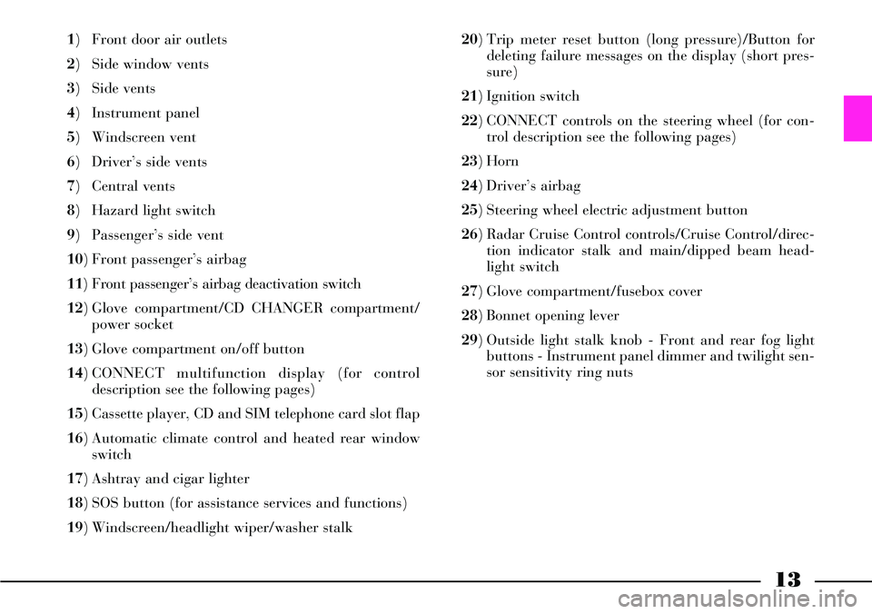
1) Front door air outlets
2) Side window vents
3) Side vents
4) Instrument panel
5) Windscreen vent
6) Driver’s side vents
7) Central vents
8) Hazard light switch
9) Passenger’s side vent
10) Front passenger’s airbag
11) Front passenger’s airbag deactivation switch
12) Glove compartment/CD CHANGER compartment/
power socket
13) Glove compartment on/off button
14) CONNECT multifunction display (for control
description see the following pages)
15) Cassette player, CD and SIM telephone card slot flap
16) Automatic climate control and heated rear window
switch
17) Ashtray and cigar lighter
18) SOS button (for assistance services and functions)
19) Windscreen/headlight wiper/washer stalk 20) Trip meter reset button (long pressure)/Button for
deleting failure messages on the display (short pres-
sure)
21) Ignition switch
22) CONNECT controls on the steering wheel (for con-
trol description see the following pages)
23) Horn
24) Driver’s airbag
25) Steering wheel electric adjustment button
26) Radar Cruise Control controls/Cruise Control/direc-
tion indicator stalk and main/dipped beam head-
light switch
27) Glove compartment/fusebox cover
28) Bonnet opening lever
29) Outside light stalk knob - Front and rear fog light
buttons - Instrument panel dimmer and twilight sen-
sor sensitivity ring nuts
Page 16 of 386
15
THESIS CONNECT infotelematic
system, in its most refined version,
includes: colour TV set, sound sys-
tem with cassette player, CD-
ROM/Audio CD player, CD-chang-
er, GSM cell phone, navigator, trip
computer and voice commands (for
certain functions of cell phone,
audio system and navigator).
The following pages describe the
system controls and main functions.
The car is provided with a special
supplement dealing with CONNECT
infotelematic system to be used as
quick reference guide for using the
system. Read through this supple-
ment carefully and keep it always
within reach (e.g. in the glove com-
partment).
IMPORTANTFor the navigation
system of the CONNECT, only use
only the original CD provided with
the car or, in any case other CDs of
the same brand.If you drive with the vol-
ume too high you put both
your own life and that of
others in jeopardy. You should
adjust the volume so that you can
hear noises from outside the car
(e.g. horns, ambulance/police
sirens, etc.).
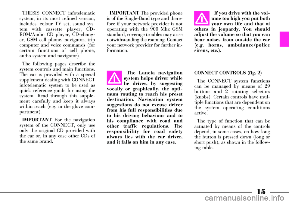
CONNECT CONTROLS (fig. 2)
The CONNECT system functions
can be managed by means of 29
buttons and 2 rotating selectors
(knobs). Certain controls have mul-
tiple functions that are dependent on
the system operating conditions
active.
The type of function that can be
actuated by means of the controls
depend, in some cases, on how long
the button is pressed down (long or
short push), as shown in the follow-
ing table. The Lancia navigation
system helps driver while
he drives, by suggesting
vocally or graphically, the opti-
mum routing to reach his preset
destination. Navigation system
suggestions do not excuse driver
from his full responsibilities due
to his driving behaviour and to
his compliance with road and
other traffic regulations. The
responsibility for road safety
always lies with the car driver,
and it falls on him in any case.IMPORTANTThe provided phone
is of the Single-Band type and there-
fore if your network provider is not
operating with the 900 Mhz GSM
standard, coverage troubles may arise
notwithstanding the roaming. Contact
your network provider for further in-
formation.
Page 18 of 386
17
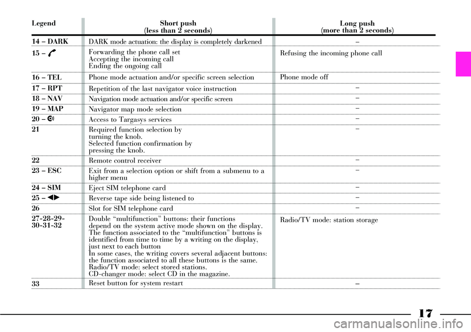
Legend
14 – DARK
15 –
£
16 – TEL
17 – RPT
18 – NAV
19 – MAP
20 – •
21
22
23 – ESC
24 – SIM
25 – ¯˙
26
27-28-29-
30-31-32
33Short push
(less than 2 seconds)
DARK mode actuation: the display is completely darkened
Forwarding the phone call set
Accepting the incoming call
Ending the ongoing call
Phone mode actuation and/or specific screen selection
Repetition of the last navigator voice instruction
Navigation mode actuation and/or specific screen
Navigator map mode selection
Access to Targasys services
Required function selection by
turning the knob.
Selected function confirmation by
pressing the knob.
Remote control receiver
Exit from a selection option or shift from a submenu to a
higher menu
Eject SIM telephone card
Reverse tape side being listened to
Slot for SIM telephone card
Double “multifunction” buttons: their functions
depend on the system active mode shown on the display.
The function associated to the “multifunction” buttons is
identified from time to time by a writing on the display,
just next to each button
In some cases, the writing covers several adjacent buttons:
the function associated to all these buttons is the same.
Radio/TV mode: select stored stations.
CD-changer mode: select CD in the magazine.
Reset button for system restart Long push
(more than 2 seconds)
–
Refusing the incoming phone call
Phone mode off
–
–
–
–
–
–
–
–
–
–
Radio/TV mode: station storage–
Page 65 of 386
64
fig. 47
L0A0310b
Recalling the “parking” position
of the external rear view mirror
on passenger side
To automatically recall the “park-
ing” position of the external passen-
ger rear view mirror, proceed as fol-
lows:
– with the car stopped and the igni-
tion key at MAR, engage the reverse
gear; the mirror will be automatical-
ly brought back to the previously
stored position .
If no “parking” position has been
stored, when engaging reverse the
passenger mirror slightly lowers
than normally to a preset position to
facilitate the driver during parking.
The rear view mirror will automat-
ically return to its initial position
after about 10 seconds from reverse
gear disengagement, or immediately
after exceeding a speed of 10 km/h
with forward gear. IMPORTANTThe “parking” posi-
tion memorisation and recall can
only be performed with ignition key
at MAR.
Automatic realignment
of external rear view mirrors
Every time the ignition key is
turned to MAR, the external rear
view mirrors automatically return to
the latest position reached and/or
recalled before removing the key.
This enables rear view mirror
alignment if, when the car is parked,
one of the rear view mirror has been
manually and/or accidentally
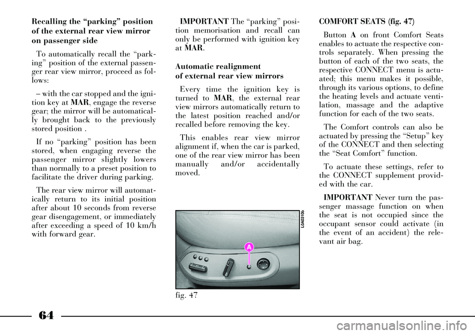
moved.COMFORT SEATS (fig. 47)
Button Aon front Comfort Seats
enables to actuate the respective con-
trols separately. When pressing the
button of each of the two seats, the
respective CONNECT menu is actu-
ated; this menu makes it possible,
through its various options, to define
the heating levels and actuate venti-
lation, massage and the adaptive
function for each of the two seats.
The Comfort controls can also be
actuated by pressing the “Setup” key
of the CONNECT and then selecting
the “Seat Comfort” function.
To actuate these settings, refer to
the CONNECT supplement provid-
ed with the car.
IMPORTANTNever turn the pas-
senger massage function on when
the seat is not occupied since the
occupant sensor could activate (in
the event of an accident) the rele-
vant air bag.
Page 79 of 386
78
The pretensioner does not require
any maintenance or greasing.
Anything that modifies its original
conditions invalidates its efficiency.
If due to unusual natural events
(floods, sea storm, etc.) the device
has been affected by water and mud,
it must necessarily be replaced.
The pretensioner can
only be used once. After a
collision that has trig-
gered it, have it replaced at a
Lancia Dealership Pretensioner
validity is written on the plate
located on the front left door post
near door hinges. The preten-
sioners should be replaced at a
Lancia Dealership as this date
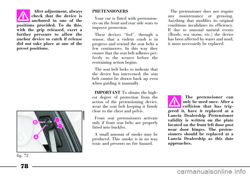
approaches.After adjustment, always
check that the device is
anchored in one of the
positions provided. To do this,
with the grip released, exert a
further pressure to allow the
anchor device to catch if release
did not take place at one of the
preset positions. PRETENSIONERS
Your car is fitted with pretension-
ers on the front and rear side seats to
improve protection.
These devices “feel”, through a
sensor, that a violent crash is in
progress and rewind the seat belts a
few centimetres. In this way they
ensure that the seat belt adheres per-
fectly to the wearer before the
restraining action begins.
The seat belt locks to indicate that
the device has intervened; the seat
belt cannot be drawn back up even
when guiding it manually.
IMPORTANTTo obtain the high-
est degree of protection from the
action of the pretensioning device,
wear the seat belt keeping it firmly
close to the chest and pelvis.
Front seat pretensioners activate
only if front seat belts are properly
fitted into buckles.
A small amount of smoke may be
produced. This smoke is in no way
toxic and presents no fire hazard.
fig. 72
L0A0089b
Page 86 of 386
85
Below is a summary of the rules
of safety to be followed for carry-
ing children:
1) Child restraint system should be
fitted on the rear seat as this is the
most protected area in the car in the
event of a crash.4) Always check the seat belt is
well fastened by pulling the web-
bing.
5) Only one child is to be strapped
to each retaining system.
6) Always check the seat belts do
not fit around the child’s throat.
7) While travelling do not let the
child sit incorrectly or release the
belts.
8) Passengers should never carry
children on their laps. No-one, how-
ever strong they are, can hold a child
in the event of a crash.
9) In case of an accident, replace
the seat with a new one.PRESETTING FOR MOUNTING
THE “ISOFIX TYPE” CHILD
RESTRAINT SYSTEM
THESIS is preset for mounting the
Isofix type child restraint system, a
new European standardised system
for transporting children. Isofix type
child restraint system is an addition-
al option that does not prevent from
using traditional child restraint sys-
tems. Isofix type child's seat covers
three weight groups: 0, 0+and 1.
Due to its different anchoring sys-
tem, the Isofix type child's seat shall
be anchored using the proper metal
brackets set between rear seat back
and cushion, shown in figures 81
and82.
It is possible to mount both the tra-
ditional child restraint system and
the Isofix type one. Max. two Isofix
type child's seats can be mounted on
the rear seat using the proper cou-
plings.
On the front passenger seat it is
possible to mount only traditional
child's seats. Children must never be
seated in the front pas-
senger seat in cars with
passenger’s front airbag.
2) In case of passenger airbag
deactivation check that instrument
panel warning light Fis on to
make sure that deactivation has
actually taken place .
3) Follow the instructions for fas-
tening the specific child restraint
system you are using which must be
provided by the manufacturer. Keep
the child restraint system installa-
tion instructions with the car papers
and with this handbook. Never use a
child restraint system without the
installation instructions.
Page 88 of 386
87
fig. 84
L0A0420b
fig. 85
L0A0255b
For proper mounting, proceed as
follows:
– remove the upper tether on the
back of the child's restraint system;
– check whether the release lever B
(fig. 83) is at rest position (inward);– identify the brackets A(fig. 83)
and mount the child restraint system
with the retainers C(fig. 83) aligned
to the brackets;
– push the child restraint system
until hearing the locking clicks;
– check for proper locking by mov-
ing the child's seat with force: the
built-in safety mechanism actually
inhibit improper coupling with just
one coupling locked;
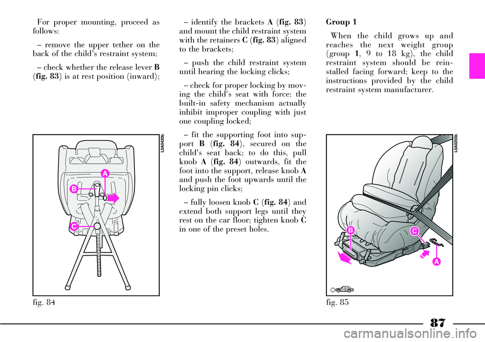
– fit the supporting foot into sup-
port B(fig. 84), secured on the
child's seat back; to do this, pull
knob A(fig. 84) outwards, fit the
foot into the support, release knob A
and push the foot upwards until the
locking pin clicks;
– fully loosen knob C(fig. 84) and
extend both support legs until they
rest on the car floor; tighten knob C
in one of the preset holes.Group 1
When the child grows up and
reaches the next weight group
(group 1, 9 to 18 kg), the child
restraint system should be rein-
stalled facing forward; keep to the
instructions provided by the child
restraint system manufacturer.
Page 106 of 386
INSTRUMENT PANEL
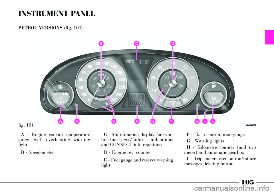
PETROL VERSIONS (fig. 101)
A- Engine coolant temperature
gauge with overheating warning
light
B- SpeedometerC- Multifunction display for sym-
bols/messages/failure indications
and CONNECT info repetition
D- Engine rev. counter
E- Fuel gauge and reserve warning
lightF- Flash consumption gauge
G- Warning lights
H- Kilometre counter (and trip
meter) and automatic gearbox
I- Trip meter reset button/failure
messages deleting button
fig. 101L0A0230b
105
Page 107 of 386
106
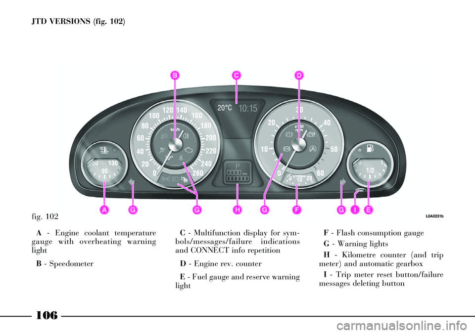
JTD VERSIONS (fig. 102)
fig. 102L0A0231b
A- Engine coolant temperature
gauge with overheating warning
light
B- SpeedometerC- Multifunction display for sym-
bols/messages/failure indications
and CONNECT info repetition
D - Engine rev. counter
E- Fuel gauge and reserve warning
lightF- Flash consumption gauge
G- Warning lights
H- Kilometre counter (and trip
meter) and automatic gearbox
I- Trip meter reset button/failure
messages deleting button
Page 111 of 386
110
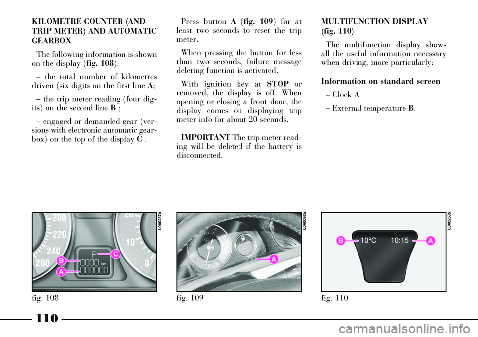
KILOMETRE COUNTER (AND
TRIP METER) AND AUTOMATIC
GEARBOX
The following information is shown
on the display (fig. 108):
– the total number of kilometres
driven (six digits on the first line A;
– the trip meter reading (four dig-
its) on the second line B ;
– engaged or demanded gear (ver-
sions with electronic automatic gear-
box) on the top of the display C .Press button A(fig. 109) for at
least two seconds to reset the trip
meter.
When pressing the button for less
than two seconds, failure message
deleting function is activated.
With ignition key at STOPor
removed, the display is off. When
opening or closing a front door, the
display comes on displaying trip
meter info for about 20 seconds.
IMPORTANTThe trip meter read-
ing will be deleted if the battery is
disconnected.
fig. 108
L0A0237b
fig. 109
L0A0092b
MULTIFUNCTION DISPLAY
(fig. 110)
The multifunction display shows
all the useful information necessary
when driving, more particularly:
Information on standard screen
– Clock A
– External temperature B.
fig. 110
L0A0258b