warning lights Lancia Thesis 2006 Owner handbook (in English)
[x] Cancel search | Manufacturer: LANCIA, Model Year: 2006, Model line: Thesis, Model: Lancia Thesis 2006Pages: 386, PDF Size: 8.69 MB
Page 10 of 386
9
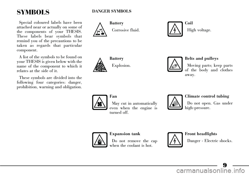
Battery
Corrosive fluid.
SYMBOLS
Special coloured labels have been
attached near or actually on some of
the components of your THESIS.
These labels bear symbols that
remind you of the precautions to be
taken as regards that particular
component.
A list of the symbols to be found on
your THESIS is given below with the
name of the component to which it
relates at the side of it.
These symbols are divided into the
following four categories: danger,
prohibition, warning and obligation.DANGER SYMBOLS
Battery
Explosion.
Fan
May cut in automatically
even when the engine is
turned off.
Expansion tank
Do not remove the cap
when the coolant is hot.
Coil
High voltage.
Belts and pulleys
Moving parts; keep parts
of the body and clothes
away.
Climate control tubing
Do not open. Gas under
high-pressure.
Front headlights
Danger - Electric shocks.
Page 13 of 386
12
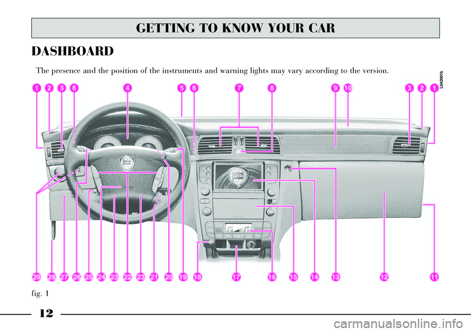
fig. 1
DASHBOARD
The presence and the position of the instruments and warning lights may vary according to the version.
L0A0001b
GETTING TO KNOW YOUR CAR
Page 74 of 386
73
Improper use of the elec-
trical window winders can
be dangerous. Before and
during their operation ensure
that any passengers in the car are
not at risk from the moving glass
either by personal objects getting
caught in the mechanism or by
being injured by it directly.
Always remove the ignition key
when you get out of the car to
prevent the electrical window
winders being operated acciden-
tally and constituting a danger to
the people left in the car. IMPORTANT In the event that the
anti-trap function is activated 5
times in only 1 minute, the system
will automatically enter the “recov-
ery” mode (self-protection). This
condition is pointed out by the fact
that, in the closing phase, the win-
dow goes up in jerks.
It is therefore necessary in this case
to carry out the system restore pro-
cedure by operating window open-
ing control or turning the ignition
key to STOPand then to MAR.
Regular operation is restored if no
malfunction is present: otherwise
contact a Lancia Dealership.
In the event that the system detects
a malfunction, the failure message
and symbol ª!will appear on the
instrument panel display (see
“Window anti-trap safety system” at
paragraph “Warning lights”).ELECTRIC
WINDOWS
ANTI-TRAP SAFETY SYSTEM
Front and rear electric windows are
provided with anti-trap safety
device. When the system control unit
detects an obstacle in the window
closing travel, it makes the window
travel stop and reverse immediately.
This system complies with regula-
tion 2000/4/EC coming soon in
force, which is destined to protect
passengers leaning out of the win-
dows. Therefore, in case of unlawful
intrusions from the outside, the anti-
trap safety device could not activate.
Page 97 of 386
96
Do not hook rigid
objects to the coat hooks
and to the support han-
dles.The airbag does not
replace seat belts but
rather increases their
effectiveness. Furthermore, the
airbag is not fired in the event of
low speed front collisions, rear-
end shunts and roll-overs. In
these cases, the passengers are
only protected by the seat belts
which for this reason must
always be fastened. When the ignition key is
turned to MAR (passenger
front airbag and rear side
bag deactivation switch at ON),
warning lights F F
and
Àwill
come on flashing for a few sec-
onds to remind the driver that
passenger front airbag and rear
side bags will be fired in the
event of a crash. Warning lights
should go out immediately after-
wards.The airbag is set to be
fired in the event of colli-
sions which are greater
than the pretensioner settings.
Consequently, for collisions in
the bracket between the two
thresholds, it is normal for only
the pretensioners to be fired.
Do not wash the seat
back rest with pres-
surised water or steam
(by hand or at automatic seat
washing stations).
Page 98 of 386

97
LIGHT SWITCH
AND STEERING
COLUMN STALKS
The devices and services controlled
by light switch and steering column
stalks can only be activated with the
ignition key at MAR, excluding the
parking lights that are switched on
only with key at STOPor removed.
Outside lights can be switched on
manually or automatically accord-
ing to daylight intensity.LIGHT SWITCH (fig. 94)
It has 5 positions:
0- outside lights off
6- side/taillights
2- dipped beam headlights
F- parking lights
AUTO- automatic outside light
switching on/off according to set
sensitivity level.
Outside lights off
Outside lights are off when ring A
is turned to 0.
Side/taillights and number plate
lights
To switch these lights on, turn ring
Ato 6.
When these lights are on, instru-
ment panel warning light 3lights
up.
When the outside lights are turned
on, the instrument panel and the
various controls and displays located
on the dashboard and central con-
sole light up.Dipped beam headlights
These lights come on when you
turn ring Ato 2.
Parking lights
With ignition key at STOPor
removed, turn ring Ato Fto switch
the parking lights on (side/tail-
lights), the relevant instrument
panel warning light will come on.
When parking lights are on, move
the left stalk downwards to switch
on only the left side lights and move
it upwards to switch on only the
right side lights. In this case the
number plate lights and the instru-
ment panel warning light will not
come on.
When parking lights are on, a
buzzer will sound when opening the
driver’s door. Buzzer sound will stop
when closing the door or switching
the lights off.
fig. 94
L0A0199b
Page 101 of 386
100
After activating the device, the set
time can be extended also within 2
minutes from when the engine is
turned off by pulling the stalk.
Keeping the stalk pulled for over 2
seconds will deactivate this function
with immediate light turning off as a
consequence.
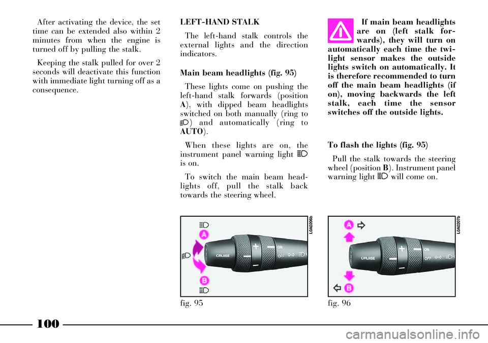
To flash the lights (fig. 95)
Pull the stalk towards the steering
wheel (position B). Instrument panel
warning light 1will come on. LEFT-HAND STALK
The left-hand stalk controls the
external lights and the direction
indicators.
Main beam headlights (fig. 95)
These lights come on pushing the
left-hand stalk forwards (position
A), with dipped beam headlights
switched on both manually (ring to
2) and automatically (ring to
AUTO).
When these lights are on, the
instrument panel warning light 1
is on.
To switch the main beam head-
lights off, pull the stalk back
towards the steering wheel.If main beam headlights
are on (left stalk for-
wards), they will turn on
automatically each time the twi-
light sensor makes the outside
lights switch on automatically. It
is therefore recommended to turn
off the main beam headlights (if
on), moving backwards the left
stalk, each time the sensor
switches off the outside lights.
fig. 95
L0A0206b
fig. 96
L0A0207b
Page 102 of 386
101
IMPORTANTThis operation will
flash the main beam headlights.
Follow the Highway Code to prevent
being fined.
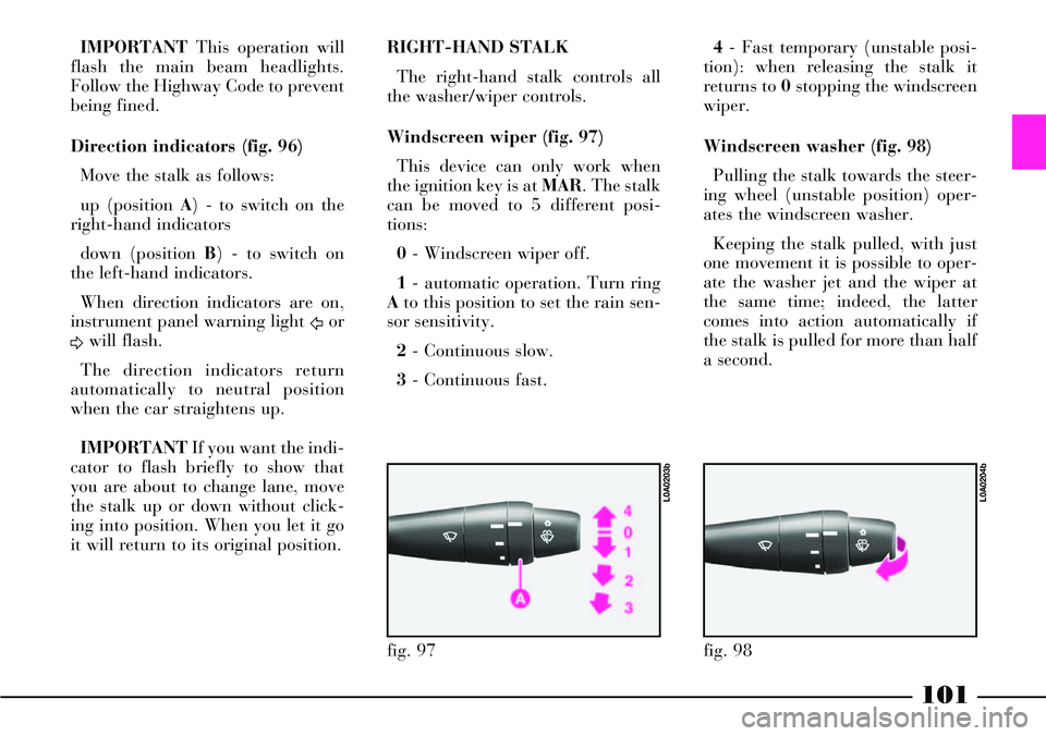
Direction indicators (fig. 96)
Move the stalk as follows:
up (position A) - to switch on the
right-hand indicators
down (position B) - to switch on
the left-hand indicators.
When direction indicators are on,
instrument panel warning light
Ÿor
∆will flash.
The direction indicators return
automatically to neutral position
when the car straightens up.
IMPORTANTIf you want the indi-
cator to flash briefly to show that
you are about to change lane, move
the stalk up or down without click-
ing into position. When you let it go
it will return to its original position.RIGHT-HAND STALK
The right-hand stalk controls all
the washer/wiper controls.
Windscreen wiper (fig. 97)
This device can only work when
the ignition key is at MAR. The stalk
can be moved to 5 different posi-
tions:
0- Windscreen wiper off.
1- automatic operation. Turn ring
Ato this position to set the rain sen-
sor sensitivity.
2- Continuous slow.
3- Continuous fast.4- Fast temporary (unstable posi-
tion): when releasing the stalk it
returns to 0stopping the windscreen
wiper.
Windscreen washer (fig. 98)
Pulling the stalk towards the steer-
ing wheel (unstable position) oper-
ates the windscreen washer.
Keeping the stalk pulled, with just
one movement it is possible to oper-
ate the washer jet and the wiper at
the same time; indeed, the latter
comes into action automatically if
the stalk is pulled for more than half
a second.
fig. 97
L0A0203b
fig. 98
L0A0204b
Page 106 of 386
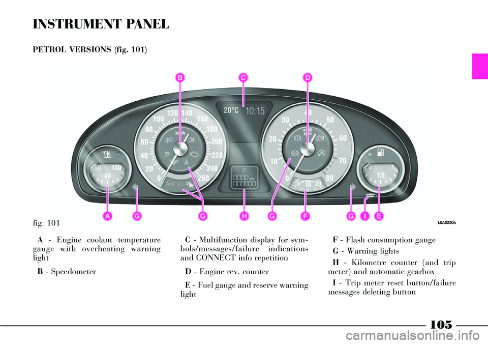
INSTRUMENT PANEL
PETROL VERSIONS (fig. 101)
A- Engine coolant temperature
gauge with overheating warning
light
B- SpeedometerC- Multifunction display for sym-
bols/messages/failure indications
and CONNECT info repetition
D- Engine rev. counter
E- Fuel gauge and reserve warning
lightF- Flash consumption gauge
G- Warning lights
H- Kilometre counter (and trip
meter) and automatic gearbox
I- Trip meter reset button/failure
messages deleting button
fig. 101L0A0230b
105
Page 107 of 386
106
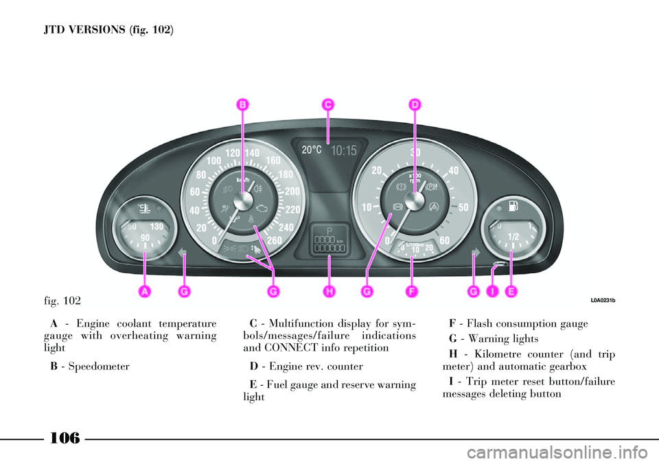
JTD VERSIONS (fig. 102)
fig. 102L0A0231b
A- Engine coolant temperature
gauge with overheating warning
light
B- SpeedometerC- Multifunction display for sym-
bols/messages/failure indications
and CONNECT info repetition
D - Engine rev. counter
E- Fuel gauge and reserve warning
lightF- Flash consumption gauge
G- Warning lights
H- Kilometre counter (and trip
meter) and automatic gearbox
I- Trip meter reset button/failure
messages deleting button
Page 116 of 386

INSTRUMENT
PANEL WARNING
LIGHTS AND
MESSAGES
On the instrument panel are set the
main warning lights. Certain warn-
ing lights with the relevant warning
messages are present also on the
instrument panel multifunction dis-
play.
Many indications/info are displayed
with a symbol only on the multifunc-
tion display with the corresponding
warnings for the driver.
IMPORTANTIndications may
vary according to the car version.GENERAL NOTES
Failure indications shown on the
multifunction display together with
buzzer sounding and warning light
(if any), are accompanied by spe-
cific warning messages(e.g. “GO
TO DEALER”, “SWITCH OFF
ENGINE”, etc.). These indications
are conciseand cautionaryand are
aimed to suggest the prompt action
the driver must adopt when a car
malfunctioning appears. These indi-
cations, however, shall not be con-
sidered as exhaustive and/or as an
alternative to the specifications con-
tained in this Owner Handbook,
which shall always be read through
carefully and thoroughly. In case of
failure indication always refer to
the specifications contained in
this chapter.Failure indications displayed on
the multifunction display are divid-
ed into two categories: very serious
failures and serious failures. The
message and the warning indication
corresponding to very serious fail-
ures are displayed alternately for
few seconds. This “cycle” is repeat-
ed indefinitely and it stops any pre-
vious indication on the display. It is
displayed every time the ignition key
is turned to MAR, until the cause of
malfunctioning is removed. To stop
this “cycle”, briefly press (less than
two seconds) the trip meter reset
button. In this case the failure sym-
bol stays on the display in the cen-
tral area until the cause of malfunc-
tioning is removed.
115