buttons Lancia Thesis 2007 Owner handbook (in English)
[x] Cancel search | Manufacturer: LANCIA, Model Year: 2007, Model line: Thesis, Model: Lancia Thesis 2007Pages: 386, PDF Size: 8.69 MB
Page 58 of 386

57
OPENING/CLOSING FROM
THE INSIDE
To open the door even when the
lock is locked, pull handle A(fig. 35
front doors -fig. 36 rear doors) set in
the upper part of the panel.
Next to each door handle are two
buttons that actuate lock
locking/unlocking:
– B button for unlocking;
– Cbutton for locking.
The red/green leds A(fig. 33 front
doors –fig. 34 rear doors) indicate
the locking/unlocking condition.
The leds come on with red light for
about 3 seconds after door locking
and with green light after unlocking.
By pulling the internal handle of
the driver’s door, all the doors or
only the driver’s door will be simul-
taneously unlocked, depending on
the setting selected on the CON-
NECT. By pulling the internal han-
dle of any other door, all the doors
are simultaneously unlocked.
fig. 36
L0A0052b
With the dead lock
device on, pressing the
external handle button of
one of the doors while unlocking
the doors by the remote control
could cause the disconnection of
the internal handle of the
involved door thus making
impossible to open that door
from the inside. To restore regu-
lar operation, just press the
remote control central door
unlocking button or button B (fig.
36) on the door panel.A led is located near each door
handle to make it easy to find the
handle in the dark. The leds light up
for about 2 minutes after turning the
ignition key to STOPor until a door
is opened.
Door open indication
The driver is informed that one or
several doors are not closed correct-
ly by the lighting of the correspond-
ing symbols on the instrument dis-
play, together with the messages
“DOOR OPEN” or “DOORS
OPEN”.
Page 62 of 386
61
fig. 41- Electrically adjustable
seats, position memorization and
heating
A- Height and back and forth
adjustment, reclining
B- Back rest angle and head
restraint position
C- Lumbar adjustment
D- Seat position memorization
buttons
E- Heating.
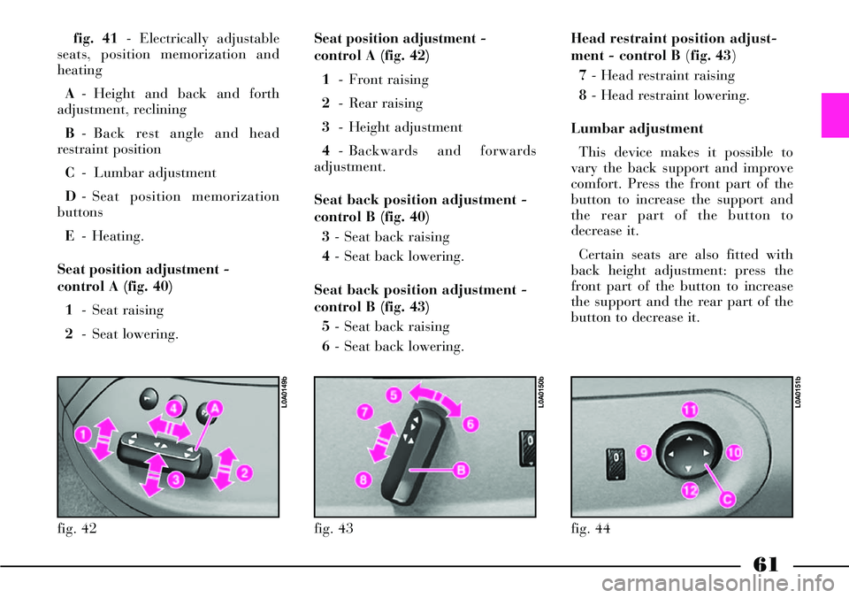
Seat position adjustment -
control A (fig. 40)
1- Seat raising
2- Seat lowering.Seat position adjustment -
control A (fig. 42)
1- Front raising
2- Rear raising
3- Height adjustment
4- Backwards and forwards
adjustment.
Seat back position adjustment -
control B (fig. 40)
3- Seat back raising
4- Seat back lowering.
Seat back position adjustment -
control B (fig. 43)
5- Seat back raising
6- Seat back lowering.
fig. 42
L0A0149b
fig. 43
L0A0150b
fig. 44
L0A0151b
Head restraint position adjust-
ment - control B (fig. 43)
7 - Head restraint raising
8- Head restraint lowering.
Lumbar adjustment
This device makes it possible to
vary the back support and improve
comfort. Press the front part of the
button to increase the support and
the rear part of the button to
decrease it.
Certain seats are also fitted with
back height adjustment: press the
front part of the button to increase
the support and the rear part of the
button to decrease it.
Page 63 of 386
62
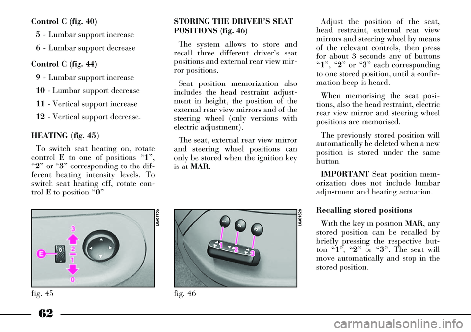
Control C (fig. 40)
5- Lumbar support increase
6- Lumbar support decrease
Control C (fig. 44)
9- Lumbar support increase
10- Lumbar support decrease
11- Vertical support increase
12- Vertical support decrease.
HEATING (fig. 45)
To switch seat heating on, rotate
control Eto one of positions “1”,
“2” or “3” corresponding to the dif-
ferent heating intensity levels. To
switch seat heating off, rotate con-
trol Eto position “0”.
fig. 45
L0A0175b
STORING THE DRIVER’S SEAT
POSITIONS (fig. 46)
The system allows to store and
recall three different driver’s seat
positions and external rear view mir-
ror positions.
Seat position memorization also
includes the head restraint adjust-
ment in height, the position of the
external rear view mirrors and of the
steering wheel (only versions with
electric adjustment).
The seat, external rear view mirror
and steering wheel positions can
only be stored when the ignition key
is at MAR.Adjust the position of the seat,
head restraint, external rear view
mirrors and steering wheel by means
of the relevant controls, then press
for about 3 seconds any of buttons
“1”, “2” or “3” each corresponding
to one stored position, until a confir-
mation beep is heard.
When memorising the seat posi-
tions, also the head restraint, electric
rear view mirror and steering wheel
positions are memorised.
The previously stored position will
automatically be deleted when a new
position is stored under the same
button.
IMPORTANTSeat position mem-
orization does not include lumbar
adjustment and heating actuation.
Recalling stored positions
With the key in position MAR, any
stored position can be recalled by
briefly pressing the respective but-
ton “1”, “2” or “3”. The seat will
move automatically and stop in the
stored position.
fig. 46
L0A0152b
Page 64 of 386
63
Stored position are recalled only if
the required position is different
from the current one and is not pos-
sible when the car speed exceeds 10
km/h.
Seats can be moved only when the
ignition key is at MARand, for
about 1 minute, also after removing
the key or turning it to STOP: dur-
ing this time, the external rear view
mirrors will not move, but when the
car is started again, they will be
automatically realigned together
with the seat position (see paragraph
“Automatic realignment of external
rear view mirrors”).
If stored seat position recalling is
still in course after this time has
elapsed, recalling will be concluded
in any case.If the engine is started during the
recalling stage, seat moving will be
stopped; once this stage is over the
seat will return automatically to the
stored position.
IMPORTANTPressing any of
memorisation or adjustment buttons
during the recalling stage, causes the
immediate stop of the seat (antipan-
ic mode).
Storing the “parking” position of
the external rear view mirror on
passenger side
You can achieve better visibility
during manoeuvres in reverse gear
(for instance, when parking the car)
by adjusting the external passenger
rear view mirror to a different posi-
tion from the one normally used.
This position can be stored by the
driver.To store the position proceed as
follows:
– with the car stopped and the igni-
tion key at MAR, engage the reverse
gear;
– adjust the position of the external
passenger rear view mirror by means
of the respective controls so as to
obtain the optimum position for the
parking manoeuvre;
– press down for at least 3 seconds
any of buttons “1”, “2” or “3” (fig.
46) used to store/recall the seat posi-
tion;
– together with the “parking” posi-
tion of the external passenger side
rear view mirror, also the seat posi-
tion, the driver rear view mirror
position and the driving position of
the external passenger side rear view
mirror are stored.
A sound signal warns the driver
that the mirror position has been
stored.
Page 68 of 386
67
ARMREST
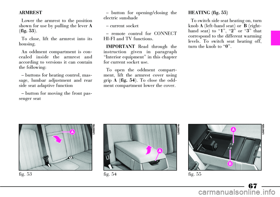
Lower the armrest to the position
shown for use by pulling the lever A
(fig. 53).
To close, lift the armrest into its
housing.
An oddment compartment is con-
cealed inside the armrest and
according to versions it can contain
the following:
– buttons for heating control, mas-
sage, lumbar adjustment and rear
side seat adaptive function
– button for moving the front pas-
senger seat– button for opening/closing the
electric sunshade
– current socket
– remote control for CONNECT
HI-FI and TV functions.
IMPORTANTRead through the
instruction given in paragraph
“Interior equipment” in this chapter
for current socket use.
To open the oddment compart-
ment, lift the armrest cover using
grip A(fig. 54). To close the odd-
ment compartment lower the cover. HEATING (fig. 55)
To switch side seat heating on, turn
knob A(left-hand seat) or B(right-
hand seat) to “1”, “2” or “3” that
correspond to the different warming
levels. To switch seat heating off,
turn the knob to “0”.
fig. 53
L0A0076b
fig. 54
L0A0074b
fig. 55
L0A0102b
Page 69 of 386
68
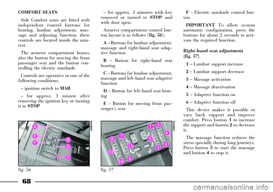
COMFORT SEATS
Side Comfort seats are fitted with
independent control buttons for
heating, lumbar adjustment, mas-
sage and adjusting function; these
controls are located inside the arm-
rest.
The armrest compartment houses
also the button for moving the front
passenger seat and the button con-
trolling the electric sunshade.
Controls are operative in one of the
following conditions:
– ignition switch to MAR
– for approx. 1 minute after
removing the ignition key or turning
it to STOP– for approx. 3 minutes with key
removed or turned to STOPand
with door open.
Armrest compartment control but-
ton layout is as follows (fig. 56):
A– Buttons for lumbar adjustment,
massage and right-hand seat adap-
tive function
B– Button for right-hand seat
heating
C– Buttons for lumbar adjustment,
massage and left-hand seat adaptive
function
D– Button for left-hand seat heat-
ing
E– Button for moving front pas-
senger’s seatF– Electric sunshade control but-
ton.
IMPORTANTTo allow system
automatic configuration, press the
buttons for about 2 seconds to acti-
vate the required function.
Right-hand seat adjustment
(fig. 57)
1 – Lumbar support increase
2– Lumbar support decrease
3– Massage activation
4– Massage deactivation
5– Adaptive function on
6– Adaptive function off
This device makes it possible to
vary back support and improve
comfort. Press button 1to increase
the support and button 2to decrease
it.
The massage function reduces the
stress specially during long journeys.
Press button 3to start the massage
and button 4to stop it.
fig. 56
L0A0312b
fig. 57
L0A0311b
Page 75 of 386

74
CONTROLS
Electric windows work with igni-
tion key at MAR.
IMPORTANTWith ignition key at
STOPor after removing it, the elec-
tric windows can be still operated for
about 2 minutes. They will deacti-
vate immediately when opening one
of the doors.
Driver’s side
On the driver’s door panel mask
there are 5 buttons (fig. 65) for con-
trolling every window.Front windows
Press buttons Aor Bto open/close
the required window (driver or pas-
senger side). Pressing briefly the
button the window “jerks”, whereas
a prolonged pressing makes the win-
dow opening or closing in “automat-
ic and continuous” mode. When
pressing again the button the win-
dow stops in the required position.
A– Front left window opening/ clos-
ing, “continuous automatic” opera-
tion during window opening/ closing
B– Front right window opening/
closing, “continuous automatic” oper-
ation during window opening/ clos-
ing.
Rear windows
Press buttons Cor Dto open/close
the required window (left or right
side). Pressing briefly the button the
window “jerks”, whereas a prolonged
pressing makes the window opening
in “automatic and continuous” mode.
When pressing again the button the
window stops in the required posi-
tion.C– Rear left window opening/clos-
ing, “continuous automatic” opera-
tion just during window opening
D– Rear right window opening/
closing, “continuous automatic” oper-
ation just during window opening
E– Rear window controls enabling/
disabling button; controls are disabled
when the button led is on.
Passenger’s side
On the passenger’s door panel
mask there is button A (fig. 66), for
opening/closing the passenger’s win-
dow.
fig. 65
L0A0050b
fig. 66
L0A0065b
Page 123 of 386

122
Follow me home device
Warning light/symbol
-
Instrument dimmer
Warning light/symbol
x
Meaning of the message
Indicates the set lighting
level (for instrument panel,
display and buttons)
Meaning of the message
Indicates that the “Follow me
home” device is on, external
lights will therefore stay on
for the set time Remarks
–
Remarks
Minimum: 30 seconds,
maximum: 210 seconds, 30
seconds intervals
Steering wheel lock
Warning light/symbol
-
Message
FOLLOW ME
XXs Message
STEERING LOCKED WHEN
DOORS CLOSEDMeaning of the message
Steering will be locked when
locking the doors
with the remote controlRemarks
– Message
DIMMER
INSTRUMENT
Page 144 of 386

143
1- Windscreen defrosting/demist-
ing vents
2- Front side windows defrost-
ing/demisting vents
3- Central directional and
adjustable vents
4- Side directional and adjustable
vents
5- Air vents on driver side
6- Air vents on passenger side
7- Directional and adjustable
vents on front doors
8- Front footwell air vents
9- Rear footwell air vents
10- Rear central directional and
adjustable vents
11- Rear side directional and
adjustable ventsThe climate control system can be
operated in one of the following
ways:
– manually, by selecting the func-
tions by means of the control panel
buttons;
– automatically, by means of the
system electronic control unit.The air is let into the passenger
compartment through a set of vents
on the dashboard, on the front door
panels, on the rear central tunnel, on
door posts and on the floor as shown
in (fig. 112).
Page 150 of 386
149
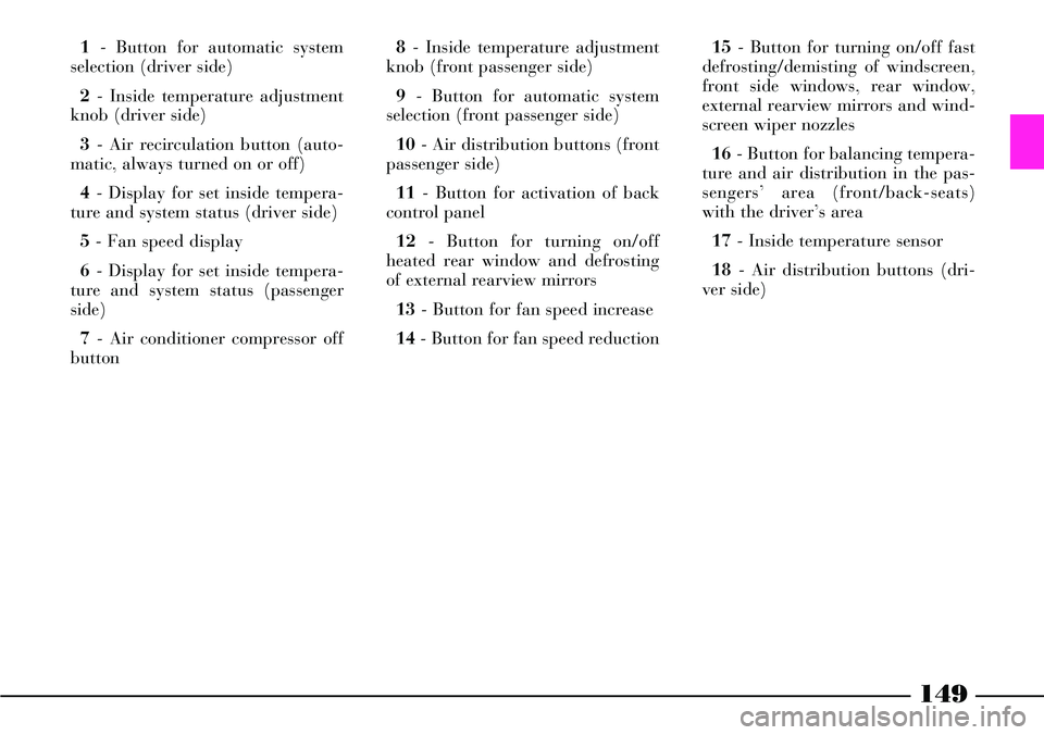
1- Button for automatic system
selection (driver side)
2- Inside temperature adjustment
knob (driver side)
3- Air recirculation button (auto-
matic, always turned on or off)
4- Display for set inside tempera-
ture and system status (driver side)
5- Fan speed display
6- Display for set inside tempera-
ture and system status (passenger
side)
7- Air conditioner compressor off
button 8- Inside temperature adjustment
knob (front passenger side)
9- Button for automatic system
selection (front passenger side)
10- Air distribution buttons (front
passenger side)
11- Button for activation of back
control panel
12- Button for turning on/off
heated rear window and defrosting
of external rearview mirrors
13- Button for fan speed increase
14- Button for fan speed reduction15- Button for turning on/off fast
defrosting/demisting of windscreen,
front side windows, rear window,
external rearview mirrors and wind-
screen wiper nozzles
16- Button for balancing tempera-
ture and air distribution in the pas-
sengers’ area (front/back-seats)
with the driver’s area
17- Inside temperature sensor
18- Air distribution buttons (dri-
ver side)