power steering Lancia Thesis 2007 Owner handbook (in English)
[x] Cancel search | Manufacturer: LANCIA, Model Year: 2007, Model line: Thesis, Model: Lancia Thesis 2007Pages: 386, PDF Size: 8.69 MB
Page 11 of 386
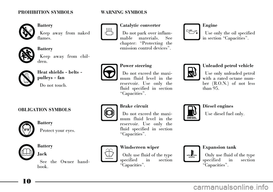
Diesel engines
Use diesel fuel only.
DIESEL
Expansion tank
Only use fluid of the type
specified in section
“Capacities”.
Battery
Protect your eyes.
Battery
Jack
See the Owner hand-
book.
OBLIGATION SYMBOLS
10
Battery
Keep away from naked
flames.
Battery
Keep away from chil-
dren.
Heat shields - belts -
pulleys - fan
Do not touch.
PROHIBITION SYMBOLS
Power steering
Do not exceed the maxi-
mum fluid level in the
reservoir. Use only the
fluid specified in section
“Capacities”.
Catalytic converter
Do not park over inflam-
mable materials. See
chapter: “Protecting the
emission control devices”.
WARNING SYMBOLS
Engine
Use only the oil specified
in section “Capacities”.
Unleaded petrol vehicle
Use only unleaded petrol
with a rated octane num-
ber (R.O.N.) of not less
than 95.
Windscreen wiper
Only use fluid of the type
specified in section
“Capacities”.
Brake circuit
Do not exceed the maxi-
mum fluid level in the
reservoir. Use only the
fluid specified in section
“Capacities”.
Page 14 of 386
13
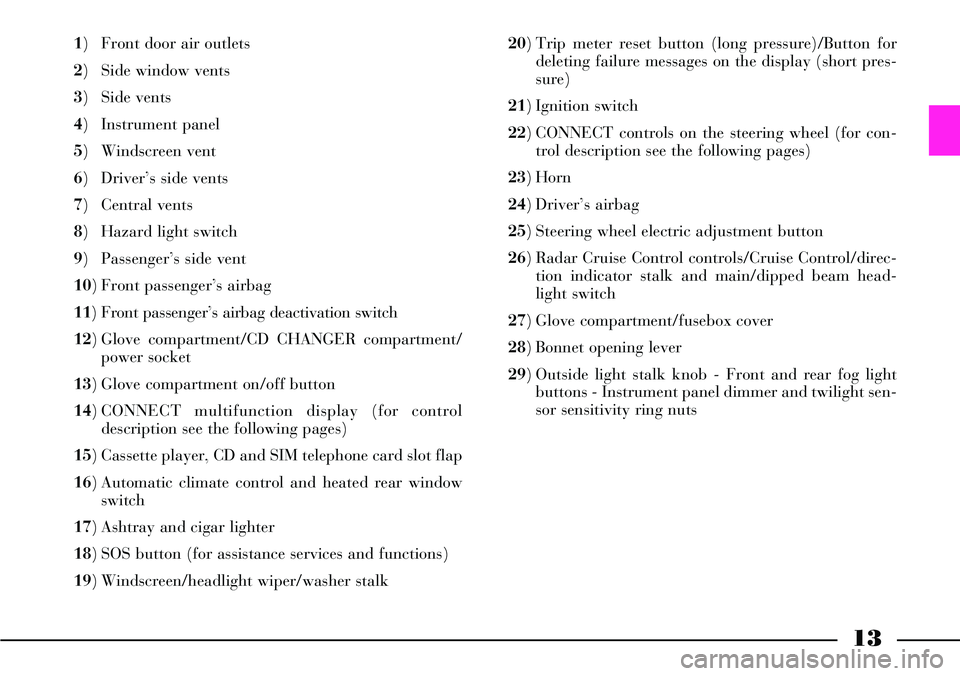
1) Front door air outlets
2) Side window vents
3) Side vents
4) Instrument panel
5) Windscreen vent
6) Driver’s side vents
7) Central vents
8) Hazard light switch
9) Passenger’s side vent
10) Front passenger’s airbag
11) Front passenger’s airbag deactivation switch
12) Glove compartment/CD CHANGER compartment/
power socket
13) Glove compartment on/off button
14) CONNECT multifunction display (for control
description see the following pages)
15) Cassette player, CD and SIM telephone card slot flap
16) Automatic climate control and heated rear window
switch
17) Ashtray and cigar lighter
18) SOS button (for assistance services and functions)
19) Windscreen/headlight wiper/washer stalk 20) Trip meter reset button (long pressure)/Button for
deleting failure messages on the display (short pres-
sure)
21) Ignition switch
22) CONNECT controls on the steering wheel (for con-
trol description see the following pages)
23) Horn
24) Driver’s airbag
25) Steering wheel electric adjustment button
26) Radar Cruise Control controls/Cruise Control/direc-
tion indicator stalk and main/dipped beam head-
light switch
27) Glove compartment/fusebox cover
28) Bonnet opening lever
29) Outside light stalk knob - Front and rear fog light
buttons - Instrument panel dimmer and twilight sen-
sor sensitivity ring nuts
Page 134 of 386
133
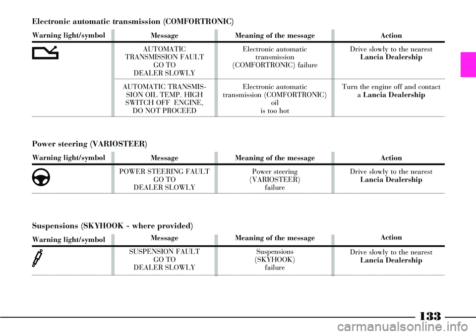
Electronic automatic transmission (COMFORTRONIC)
Warning light/symbol
t
Message
AUTOMATIC
TRANSMISSION FAULT
GO TO
DEALER SLOWLY
AUTOMATIC TRANSMIS-
SION OIL TEMP. HIGH
SWITCH OFF ENGINE,
DO NOT PROCEEDMeaning of the message
Electronic automatic
transmission
(COMFORTRONIC) failure
Electronic automatic
transmission (COMFORTRONIC)
oil
is too hot Action
Drive slowly to the nearest
Lancia Dealership
Turn the engine off and contact
a Lancia Dealership
Power steering (VARIOSTEER)
Warning light/symbol
g
Message
POWER STEERING FAULT
GO TO
DEALER SLOWLYMeaning of the message
Power steering
(VARIOSTEER)
failureAction
Drive slowly to the nearest
Lancia Dealership
Suspensions (SKYHOOK - where provided)
Warning light/symbol
‰
Message
SUSPENSION FAULT
GO TO
DEALER SLOWLYMeaning of the message
Suspensions
(SKYHOOK)
failureAction
Drive slowly to the nearest
Lancia Dealership
Page 191 of 386
190
If the sensors detect the conditions
which might cause car skidding, the
ESP system affects the engine and
the brakes by generating a torque
which makes the car recover the
right driving direction.
The system operations,
in terms of safety, should
not make the driver run
useless risks. The driving behav-
iour must always be appropriate,
according to the conditions of the
road bed, visibility and traffic.
Anyway, the driver is held
responsible for a safe driving.
The ESP system helps the driver
control the car in case of tyre grip
loss, however the forces used by
the system to control the car sta-
bility still depend on the grip
ratio between tyres and road bed.ESP SYSTEM OPERATION
ESP is automatically started when
the car is started and it cannot be
disengaged. On the contrary, it is
possible to exclude the ASR system
by pressing the related button on the
central console.
The ESP main components are the
following:
– an electric-hydraulic control unit
processing signals coming from the
various sensors and choosing the
most appropriate strategy by operat-
ing solenoid valves and the engine
control unit;
– a sensor detecting the steering
wheel rotation angle;
– 4 sensors detecting the rotation
speed of each wheel;
– a sensor detecting the car rota-
tion around a vertical axis;
– a sensor detecting side accelera-
tion (centrifugal force).The ESP core is a sensor, of aero-
nautic origin, detecting the car rota-
tions around its vertical axis.
Centrifugal forces generated when
the car is cornering are detected by a
high-sensitive side acceleration sen-
sor.
The ESP stabilizing action is based
on the signals coming from the steer-
ing wheel rotation sensors, from the
side acceleration sensors and the
wheel speed sensors, thus recogniz-
ing the driving direction selected by
the driver when turning the steering
wheel.
The control unit processes each
information coming from the sensors
and is able to recognize every single
moment of the car position and to
compare it with the direction the
driver is willing to follow. In case of
discrepancy, the control unit
instantly selects and controls the
most appropriate actions to make
the car recover the required direc-
tion: it brakes with a different inten-
sity one or more wheels and, if nec-
essary, reduces the power supplied
by the engine. Corrections are con-
Page 254 of 386

253
Remember that until the
engine has started, the
brake booster and power
steering systems will not work
and a greater effort will therefore
be required to press the brake
pedal and turn the steering
wheel. For cars equipped with
turbosupercharger in
particular, but generally
for any kind of cars, avoid abrupt
accelerations immediately before
turning the engine off. A quick
burst on the accelerator serves
absolutely no practical purpose,
wastes fuel and may damage seri-
ously the turbosupercharger
rotor bearings.EMERGENCY START-UP
If the Lancia CODE system fails to
recognise that code transmitted by
the ignition key (symbol Ytogeth-
er with message “VEHICLE PRO-
TECTION SYSTEM FAULT” on the
multifunction display) the emer-
gency start-up can be performed by
using the CODE card code.
For the correct procedure see chap-
ter “In an emergency”.
Before opening the lug-
gage compartment bonnet
to reload the battery or to
connect an auxiliary battery,
carefully read and comply with
the instructions contained in the
paragraph “If battery is to be dis-
connected” in the chapter “In an
emergency”. Never bump start the
engine (by pushing, tow-
ing or coasting downhill)
as this could cause fuel to flow
into the catalytic exhaust system
and damage it beyond repair.
IMPORTANTIf the engine turns
off while the car is running, the
Lancia CODE symbol Yand the
message “VEHICLE PROTECTION
SYSTEM FAULT” may appear on
the multifunction display when the
engine starts again. In this case
check that the warning light switch-
es off when turning the engine off
and on again with the car stationary.
Otherwise contact aLancia
Dealership.
Page 256 of 386
255
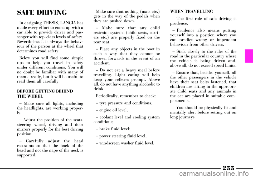
SAFE DRIVING
In designing THESIS, LANCIA has
made every effort to come up with a
car able to provide driver and pas-
senger with top-class levels of safety.
Nevertheless it is always the behav-
iour of the person at the wheel that
determines road safety.
Below you will find some simple
tips to help you travel in safety
under different conditions. You will
no doubt be familiar with many of
them already, but it will be useful to
read them all carefully.
BEFORE GETTING BEHIND
THE WHEEL
– Make sure all lights, including
the headlights, are working proper-
ly.
– Adjust the position of the seats,
steering wheel, driving and door
mirrors properly for the best driving
position.
– Carefully adjust the head
restraints so that the back of the
head and not the nape of the neck is
supported. Make sure that nothing (mats etc.)
gets in the way of the pedals when
they are pushed down.
– Make sure that any child
restraint systems (child seats, carri-
ers etc.) are properly fixed on the
rear seat.
– Place any objects in the boot in
such a way that they cannot be
thrown forwards in the event of an
accident.
– Do not eat a heavy meal before
travelling. Light eating will help
keep your reflexes prompt. Above
all, do not have anything alcoholic to
drink.
Periodically, remember to check:
– tyre pressure and conditions;
– engine oil level;
– coolant level and cooling system
conditions;
– brake fluid level;
– power steering fluid level;
– windscreen washer fluid level. WHEN TRAVELLING
– The first rule of safe driving is
prudence.
– Prudence also means putting
yourself into a position where you
can predict wrong or imprudent
behaviour from other drivers.
– Stick closely to the rules of the
road in the particular country where
the vehicle is being driven and,
above all, do not exceed speed limits.
– Ensure that, besides yourself, all
the other passengers in the vehicle
have their seat belts fastened, that
children are sitting in the appropri-
ate child seats and any animals in
the car are placed in suitable com-
partments.
– You should be physically fit and
mentally alert before setting out on
long journeys.
Page 274 of 386

273
7) Start the engine.
8) When the engine has started,
remove the leads in the reverse order
to before: D, C, Band finally A.
IMPORTANT If the engine fails to
start after a few attempts, do not keep
turning the key but have the car seen
to at a Lancia Dealership.
9) Put the cover back on the bat-
tery positive terminal by fitting the
lock flanges in.
10) Put the cover back and retight-
en the knob.
11) Close the boot tailgate.IMPORTANTWhen the tailgate is
closed, the boot latch is not locked.
To lock it, turn the metal insert of
the key anticlockwise in the latch.
Do not carry out this
procedure if you lack
experience: if it is not
done correctly it can cause very
intense electrical discharges and
the battery might even explode.
Do not to put naked flames or
lighted cigarettes near the battery
and do not cause sparks: risk of
explosion and fire.
Never use a battery
charger to jump start the
engine: you could damage
the electronic system, with spe-
cial reference to ignition and
injection control unit.
BUMP STARTING
Do not bump start by pushing,
towing or coasting downhill. This
way of starting could cause a rush of
fuel into the catalytic converter and
damage it beyond repair.
Remember that ifthe engine is not
running, the brake booster and the
power steering will not work. You
therefore have to use considerably
more effort on both the brake pedal
and the steering wheel.
Never connect the nega-
tive terminals of the two
batteries directly: sparks
could ignite the flammable gas
from the battery. If the auxiliary
battery is installed on another
car, prevent accidental contact
between the metal parts of the
two vehicles.
Page 277 of 386

276
8) Unscrew manually the jack han-
dle A(fig. 7) and remove it from the
container B.9) Open the tool bag and take out
the tools to be used (fig. 8):
1 – tow ring
2 – flat/cross-head screwdriver
3 – ratchet wrench
4 – ratchet wrench bush
5 – wheel bolt (for versions with
alloy rims)
6 – tool for removing the hub cap
(for versions with alloy rims)
7 – bush for unscrewing/screwing
the wheel bolts by hand8 – wrench for power steering re-
servoir cap screws
9 – wrench for actuating the sun-
roof in an emergency (where fitted)
10) On versions with alloy rims,
remove the press-fit wheel hub cap
A(fig. 9), pulling it by tool Bfitted
into C. On versions with steel rims,
remove the press-fit wheel cap A
(fig. 10).
fig. 8
L0A0326b
fig. 7
L0A0038b
fig. 9
L0A0327b
fig. 10
L0A0367b
Page 298 of 386
297
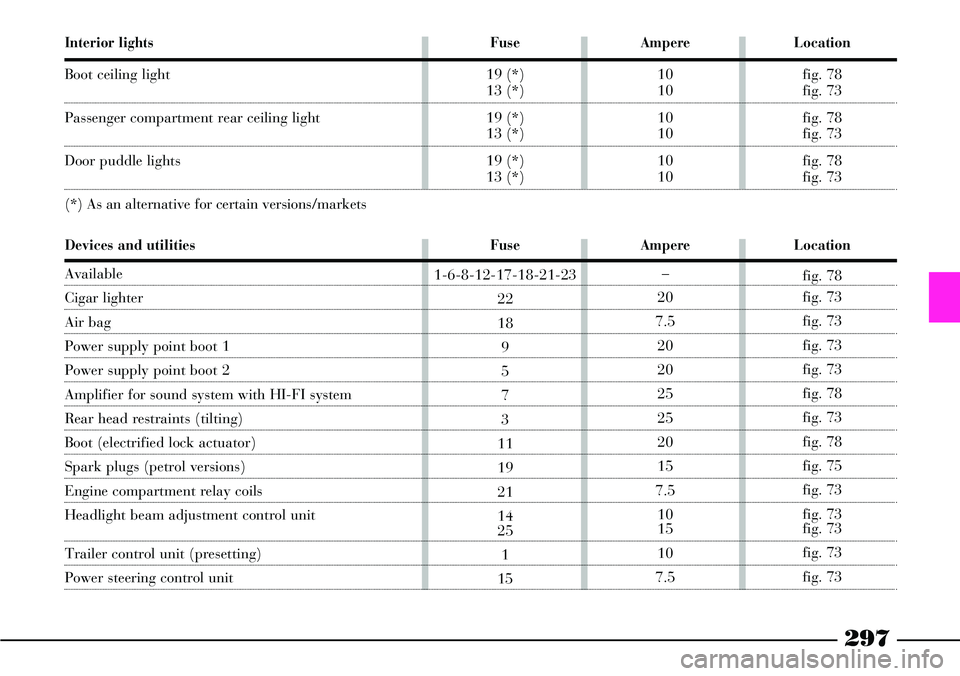
Interior lights
Boot ceiling light
Passenger compartment rear ceiling light
Door puddle lights
(*) As an alternative for certain versions/markets
Fuse
19 (*)
13 (*)
19 (*)
13 (*)
19 (*)
13 (*)
Ampere
10
10
10
10
10
10
Location
fig. 78
fig. 73
fig. 78
fig. 73
fig. 78
fig. 73
Fuse
1-6-8-12-17-18-21-23
22
18
9
5
7
3
11
19
21
14
25
1
15
Ampere
–
20
7.5
20
20
25
25
20
15
7.5
10
15
10
7.5
Location
fig. 78
fig. 73
fig. 73
fig. 73
fig. 73
fig. 78
fig. 73
fig. 78
fig. 75
fig. 73
fig. 73
fig. 73
fig. 73
fig. 73
Devices and utilities
Available
Cigar lighter
Air bag
Power supply point boot 1
Power supply point boot 2
Amplifier for sound system with HI-FI system
Rear head restraints (tilting)
Boot (electrified lock actuator)
Spark plugs (petrol versions)
Engine compartment relay coils
Headlight beam adjustment control unit
Trailer control unit (presetting)
Power steering control unit
Page 300 of 386

299
Devices and utilities
Engine control system point interface
Brake system point interface
Headlight washers
Heated rear window
Automatic gearbox starter
NIM
Passenger position point
Steering lock point
Brake Assistant point
(*) As an alternative for certain versions/markets
Braking system point (NFR 1)
Braking system point (NFR 2)
Infotelematic point
Yaw Lateral point
(*) As an alternative for certain versions/markets
Keyless System point
Driver door point
Driver door point (power supply)
Passenger door point
Fuse
22
29
15
17
17
6
14
22
19 (*)
13 (*)
19
1
6
6
19 (*)
13 (*)
19
22
11
8
11
23
Ampere
7.5
7.5
20
30
30
10
10
10
10
10
7.5
40
40
10
10
10
7.5
10
20
20
20
7.5
Location
fig. 75
fig. 73
fig. 75
fig. 73
fig. 75
fig. 73
fig. 78
fig. 78
fig. 78
fig. 73
fig. 73
fig. 75
fig. 75
fig. 73
fig. 78
fig. 73
fig. 73
fig. 78
fig. 78
fig. 73
fig. 78
fig. 73