lights Lancia Thesis 2008 Owner handbook (in English)
[x] Cancel search | Manufacturer: LANCIA, Model Year: 2008, Model line: Thesis, Model: Lancia Thesis 2008Pages: 386, PDF Size: 4.96 MB
Page 263 of 386

262
Traffic and road conditions
Heavy traffic and higher consump-
tion are synonymous, for example
when driving slowly with frequent
use of lower gears or in towns where
there are numerous traffic lights.
Winding roads, mountain roads
and bumpy roads also have a nega-
tive effect on consumption.
Enforced halts
During prolonged stops (level
crossings, etc.) the engine should be
switched off.Environmental protection has been
one of the guiding principles in the
production of the THESIS.
It is not accident that its pollution
control equipment is much more
effective than that required by cur-
rent legislation.
Nonetheless, the environment can-
not get by without a concerted effort
from everyone.
By following a few simple rules you
can avoid harming the environment
and often cut down fuel consump-
tion at the same time. On this sub-
ject, a few useful tips have been
given below to supplement those
marked by symbol #, at various
points of the handbook.
You are asked to read both the for-
mer and the latter carefully.CHEAP RUNNING THAT RESPECTS THE
ENVIRONMENT
LOOKING AFTER EMISSION
CONTROL DEVICES
The correct use of pollution control
devices not only ensures respect for
the environment but also has an
effect on the car’s performance.
Keeping these devices in good condi-
tion is therefore a fundamental rule
for driving that is easy on your
pocket and on the environment too.
The first step is to follow the
“Service Schedule” to the letter.
Only use unleaded petrol for petrol
engines (95 RON), for JTD versions
only diesel fuel (EN590 specifica-
tion).
Page 265 of 386

264
TOWING A
TRAILER
GENERAL NOTES
The car must be fitted with a
homologated tow hitch and suitable
electrical system for towing a cara-
van or a trailer. Have the tow hitch
fitted by an expert who will issue
specific documentation for use on
roads.
Fit special and/or additional
rearview mirrors in accordance with
the highway code.
Remember that towing a trailer
makes it harder for the car to climb
the maximum gradients specified,
increases braking and overtaking
distance, proportionally to the over-
all weight of the trailer.Engage a low gear when driving
downhill rather than constantly
braking.
The weight the trailer exerts on the
car’s tow hitch coupling reduces the
car’s loading capacity by the same
amount. In order to be sure you are
not exceeding the maximum towing
weight (as specified in the registra-
tion book), you have to take into
account the trailer’s fully laden
weight, including accessories and
personal luggage.
Do not exceed the speed limits for
towing a trailer in the country you
are driving in. In any case, do not
exceed the top speed of 100 km/h.
Trailer electrical connection shall
only be performed with ignition key
atSTOPor removed.
When trailer electrical connection
is on and you switch on the rear fog
lights, only the trailer rear fog lights
will come on.The ABS system will not
control the trailing brak-
ing system. Great care
should therefore be taken when
driving on slippery road surfaces.
Under no circumstances
modify the car’s braking
system for trailer braking
control. The trailer’s braking sys-
tem must be completely indepen-
dent of the car’s hydraulic sys-
tem.
The rear parking sensors
are automatically deacti-
vated when the plug of the
trailer’s electrical cable is insert-
ed in the car’s tow hitch socket.
The rear sensors activate auto-
matically when the trailer’s plug is
disconnected.
Page 266 of 386

265
TOW HITCH INSTALLATION
The tow hitch must be fixed to the
body by an expert in accordance
with the following instructions and
respecting the additional and/or
integrative information provided by
the tow hitch manufacturer.
The tow hitch to be fitted must
comply with the current regulations
in force, with reference to Directive
94/20/EEC and subsequent modifi-
cations.
Use a tow hitch suited for the max-
imum towable load of the car ver-
sion on which the tow hitch is to be
fitted.
Use a unified coupling for the elec-
trical connections. The coupling is
generally fitted on a specific mount
fastened to the tow hitch. A specific
trailer lights control unit shall be
installed on the car.For the electric connections, a 7
pole 12VDC coupling must be used
(CUNA/UNI and ISO/DIN stan-
dards). Follow the instructions pro-
vided by the manufacturer of the car
and/or the tow hitch.
The electrical brake (where rele-
vant) or other device (electrical
winch, etc.) must be powered direct-
ly from the battery by means of a
lead with a cross-section area no
smaller than 2.5 mm
2.
IMPORTANTUse the electrical
brake or winch only when the engine
is running.
In addition to the electrical connec-
tions, only the power wire for an
additional electrical brake and for
internal trailer lighting with a power
not exceeding 15W can be connect-
ed to the car’s electrical system.
For connections use the specific
control unit with battery cable not
less than 2.5 mm
2.INSTALLATION DIAGRAM (fig. 1)
Fasten the tow hitch in the points
marked with (1) using 18 M10
screws and, in the points marked
with (2) use four M8 screws.
Fasten the tow hitch to the body
avoiding any type of drilling and
trimming of the rear bumpers that
remains visible when the tow hitch is
removed.
IMPORTANTFasten a tag in a
clearly visible position at the same
height as the tow hitch. The tag is
compulsory. It must be adequately
sized, made of suitable material and
carry the following information:
MAX LOAD ON BALL COUPLING
75 kg.
After assembly, seal the fastening
screws holes to prevent exhaust fumes
from entering the passenger compart-
ment.
Page 275 of 386

274
Signal the presence of
the stopped car according
to the laws in force: haz-
ard lights, reflecting triangle, etc.
Passengers should get out of the
car and stay clear from oncoming
traffic while the wheel is being
changed.
IF A TYRE
IS PUNCTURED
Follow the instructions on this and
the following pages to use the jack
and the spare wheel correctly.If the wheel is being
changed on a steep or
badly surfaced road,
place wedges or other suitable
material under the wheels to stop
the car from moving.
Have the punctured tyre
repaired and fitted back as soon
as possible. Do not lubricate the
bolt threads before fitting them
back: they could come loose.
Wheel bolts are specific
for the type of rim (alloy
or steel) fitted. Never use,
also if in an emergency, wheel
bolts for another type of rim.
When changing rims (alloy rims
instead of steel ones or vice
versa), also the whole wheel bolt
set shall be changed with other
bolts specific for the new type of
rim adopted.The jack should only be
used to change a wheel on
the car for which it was
designed. It should not be put to
other uses or employed to raise
other models of car. Under no
circumstances should it be used
when carrying out repairs under
the car.
An incorrectly positioned jack
may cause the car to fall.
Do not use the jack to lift loads
exceeding those indicated on the
label attached to the jack itself.
The wheel cap may fly off when
the car is moving if it is not fas-
tened correctly. Never tamper
with the inflation valve. Do not
insert tools between the rim and
the tyre.
Check the tyre and spare wheel
pressure regularly. Tyre pressure
is shown in the “Technical
Specifications” chapter.
Page 282 of 386
281
You should, where pos-
sible, have your bulbs
changed at a Lancia
Dealership. The correct operation
and slant of headlights is essen-
tial for safe driving and compli-
ance with legal requirements.IF A BULB BURNS
OUT
Modifications or repairs
to the electrical system
carried out incorrectly
and without bearing the features
of the system in mind can cause
malfunctions with the risk of fire.
The bulbs of (bi-Xeno)
gas-discharge headlights
must be replaced by a
Lancia Dealership.
Only touch the metal
part when handling halo-
gen bulbs. You will
reduce the light intensity and
possibly compromise bulb life by
touching the glass bulb. If you
touch the bulb accidentally, rub
it with a cloth moistened with
alcohol and leave it to dry.
Halogen bulbs contain
pressurised gas which, if
broken, may cause small
fragments of glass to be projected
outwards.
Due to high voltage, the
bulb of bi-Xeno gas-dis-
charge headlights must
only be replaced by experts: dan-
ger of death! Contact the Lancia
Dealership.
Page 284 of 386
283
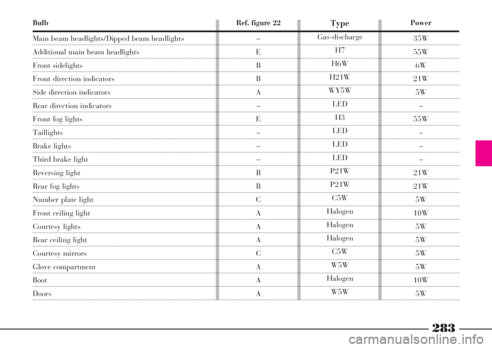
Bulb
Main beam headlights/Dipped beam headlights
Additional main beam headlights
Front sidelights
Front direction indicators
Side direction indicators
Rear direction indicators
Front fog lights
Taillights
Brake lights
Third brake light
Reversing light
Rear fog lights
Number plate light
Front ceiling light
Courtesy lights
Rear ceiling light
Courtesy mirrors
Glove compartment
Boot
Doors
Power
35W
55W
6W
21W
5W
–
55W
–
–
–
21W
21W
5W
10W
5W
5W
5W
5W
10W
5W
Type
Gas-discharge
H7
H6W
H21W
WY5W
LED
H3
LED
LED
LED
P21W
P21W
C5W
Halogen
Halogen
Halogen
C5W
W5W
Halogen
W5W
Ref. figure 22
–
E
B
B
A
–
E
–
–
–
B
B
C
A
A
A
C
A
A
A
Page 285 of 386
284
IF AN EXTERIOR
BULB BURNS OUT
FRONT LIGHT CLUSTER
The front light cluster includes
main beam headlights/dipped beam
headlights, additional main beam
headlights, direction indicators and
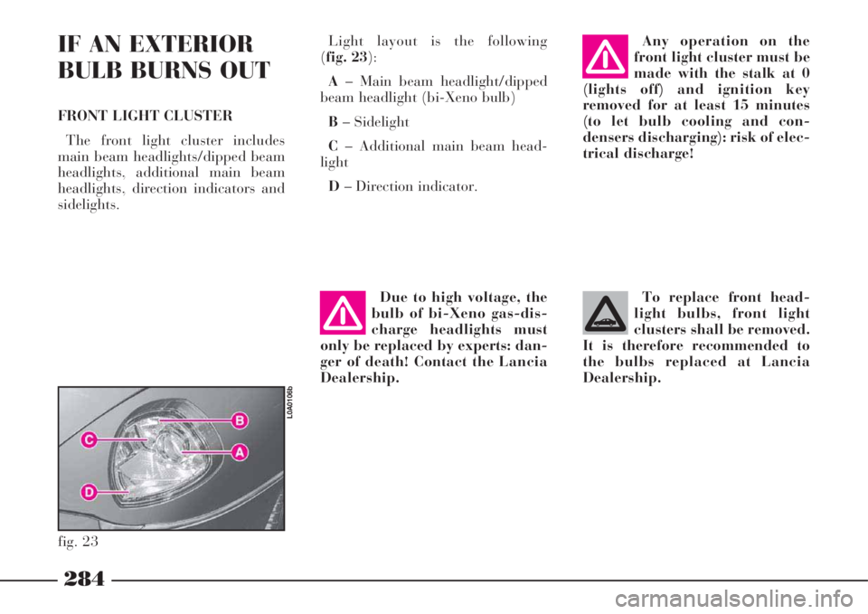
sidelights.Light layout is the following
(fig. 23):
A– Main beam headlight/dipped
beam headlight (bi-Xeno bulb)
B– Sidelight
C– Additional main beam head-
light
D– Direction indicator.Any operation on the
front light cluster must be
made with the stalk at 0
(lights off) and ignition key
removed for at least 15 minutes
(to let bulb cooling and con-
densers discharging): risk of elec-
trical discharge!
fig. 23
L0A0106b
To replace front head-
light bulbs, front light
clusters shall be removed.
It is therefore recommended to
the bulbs replaced at Lancia
Dealership.Due to high voltage, the
bulb of bi-Xeno gas-dis-
charge headlights must
only be replaced by experts: dan-
ger of death! Contact the Lancia
Dealership.
Page 286 of 386
285
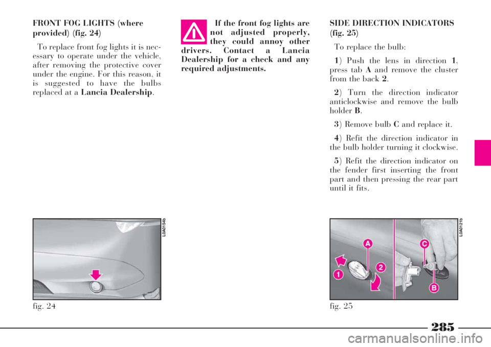
SIDE DIRECTION INDICATORS
(fig. 25)
To replace the bulb:
1) Push the lens in direction 1,
press tab Aand remove the cluster
from the back 2.
2) Turn the direction indicator
anticlockwise and remove the bulb
holderB.
3) Remove bulb Cand replace it.
4) Refit the direction indicator in
the bulb holder turning it clockwise.
5) Refit the direction indicator on
the fender first inserting the front
part and then pressing the rear part
until it fits. If the front fog lights are
not adjusted properly,
they could annoy other
drivers. Contact a Lancia
Dealership for a check and any
required adjustments.
fig. 24
L0A0154b
fig. 25
L0A0121b
FRONT FOG LIGHTS (where
provided) (fig. 24)
To replace front fog lights it is nec-
essary to operate under the vehicle,
after removing the protective cover
under the engine. For this reason, it
is suggested to have the bulbs
replaced at a Lancia Dealership.
Page 287 of 386
286
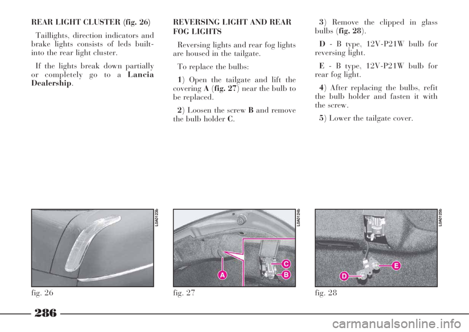
REAR LIGHT CLUSTER (fig. 26)
Taillights, direction indicators and
brake lights consists of leds built-
into the rear light cluster.
If the lights break down partially
or completely go to a Lancia
Dealership.REVERSING LIGHT AND REAR
FOG LIGHTS
Reversing lights and rear fog lights
are housed in the tailgate.
To replace the bulbs:
1) Open the tailgate and lift the
coveringA(fig. 27) near the bulb to
be replaced.
2) Loosen the screw Band remove
the bulb holder C.3) Remove the clipped in glass
bulbs (fig. 28).
D- B type, 12V-P21W bulb for
reversing light.
E- B type, 12V-P21W bulb for
rear fog light.
4) After replacing the bulbs, refit
the bulb holder and fasten it with
the screw.
5) Lower the tailgate cover.
fig. 26
L0A0123b
fig. 27
L0A0124b
fig. 28
L0A0125b
Page 288 of 386
287
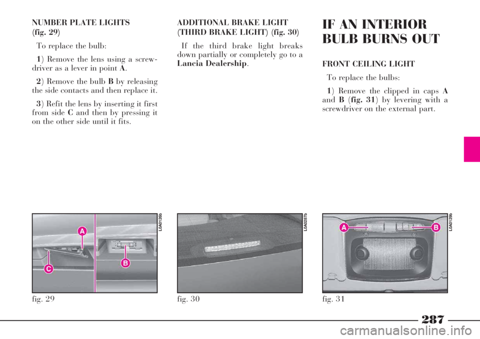
NUMBER PLATE LIGHTS
(fig. 29)
To replace the bulb:
1) Remove the lens using a screw-
driver as a lever in point A.
2) Remove the bulb Bby releasing
the side contacts and then replace it.
3) Refit the lens by inserting it first
from side Cand then by pressing it
on the other side until it fits.ADDITIONAL BRAKE LIGHT
(THIRD BRAKE LIGHT) (fig. 30)
If the third brake light breaks
down partially or completely go to a
Lancia Dealership.IF AN INTERIOR
BULB BURNS OUT
FRONT CEILING LIGHT
To replace the bulbs:
1) Remove the clipped in caps A
andB(fig. 31) by levering with a
screwdriver on the external part.
fig. 29
L0A0126b
fig. 30
L0A0287b
fig. 31
L0A0129b