ABS Lancia Voyager 2012 Owner handbook (in English)
[x] Cancel search | Manufacturer: LANCIA, Model Year: 2012, Model line: Voyager, Model: Lancia Voyager 2012Pages: 344, PDF Size: 3.95 MB
Page 40 of 344

Gas props support the liftgate in the
open position. However, because the
gas pressure drops with temperature,
it may be necessary to assist the props
when opening the liftgate in cold
weather.
OCCUPANT RESTRAINTS
Some of the most important safety
features in your vehicle are the re-
straint systems:
Three-point lap and shoulder beltsfor all seating positions
Advanced Front Air Bags for driver and front passenger
Supplemental Active Head Re- straints (AHR) located on top of the
front seats (integrated into the head
restraint)
Supplemental Side Air Bag Inflat- able Curtains (SABIC) that span
the front, second, and third row
seating for the driver and passen-
gers seated next to a window
Supplemental Seat-Mounted Side Air Bags (SAB)
An energy-absorbing steering col- umn and steering wheel Knee bolsters/blockers for front
seat occupants (for versions/
markets, where provided)
Front seat belts incorporate preten- sioners that may enhance occupant
protection by managing occupant
energy during an impact event
All seat belt systems (except the driver’s) include Automatic Lock-
ing Retractors (ALRs), which lock
the seat belt webbing into position
by extending the belt all the way
out and then adjusting the belt to
the desired length to restrain a child
seat or secure a large item in a seat
If you will be carrying children too
small for adult-sized seat belts, the
seat belts or the ISOFIX feature also
can be used to hold infant and child
restraint systems. For more informa-
tion on ISOFIX, see ISOFIX — Child
Seat Anchorage System.
NOTE:
The Advanced Front Air Bags have
a multistage inflator design. This
allows the air bag to have different
rates of inflation based on several
factors, including the severity and
type of collision. Please pay close attention to the infor-
mation in this section. It tells you how
to use your restraint system properly,
to keep you and your passengers as
safe as possible.
WARNING!
In a collision, you and your passen-
gers can suffer much greater injuries
if you are not properly buckled up.
You can strike the interior of your
vehicle or other passengers, or you
can be thrown out of the vehicle.
Always be sure you and others in
your vehicle are buckled up prop-
erly.
Buckle up even though you are an
excellent driver, even on short trips.
Someone on the road may be a poor
driver and cause a collision that in-
cludes you. This can happen far away
from home or on your own street.
Research has shown that seat belts
save lives, and they can reduce the
seriousness of injuries in a collision.
Some of the worst injuries happen
when people are thrown from the ve-
hicle. Seat belts reduce the possibility
of ejection and the risk of injury
34
Page 157 of 344

2. Slide the console forward into the
floor bracket.
3. Rotate the rear of the console down
until it is resting on the floor bracket.
4. Push down on the rear of the con-
sole until it is seated in the rear floor
bracket.
5. Pull up on the console to be sure it
is firmly latched.WARNING!
In an accident, serious injury could
result if the removable floor console
is not properly installed. Always be
sure the removable floor console is
fully latched.
SUPER CONSOLE (for
versions/markets, where
provided)
The Super Console contains multiple
storage areas, front lower pass
through, top forward bin, top rear-
ward bin and rear pull out drawer.
The super console contains a pass
through storage area accessible for
both the driver and front passenger. The super console tambour doors are
opened by pushing down on the finger
tabs and sliding the door. The front
tambour door slides forward, the rear
tambour door slides rearward.
NOTE:
The front cupholder light ring and
pass through lighting is controlled
by a dimming switch located on
the instrument panel, refer to
“Lights” in “Understanding The
Features Of Your Vehicle” for fur-
ther information.
Located in the back of the super con-
sole is a storage drawer and cuphold-
ers for the rear passengers.
Front Lower Pass Through
Super Console
1 — Front Sliding Tambour Door
2 — Cupholder Light Ring
3 — Rear Sliding Tambour Door
Rear Drawer Storage
151
Page 170 of 344
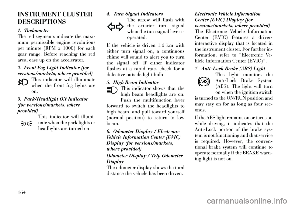
INSTRUMENT CLUSTER
DESCRIPTIONS
1. Tachometer
The red segments indicate the maxi-
mum permissible engine revolutions
per minute (RPM x 1000) for each
gear range. Before reaching the red
area, ease up on the accelerator.
2. Front Fog Light Indicator (for
versions/markets, where provided)This indicator will illuminate
when the front fog lights are
on.
3. Park/Headlight ON Indicator
(for versions/markets, where
provided) This indicator will illumi-
nate when the park lights or
headlights are turned on. 4. Turn Signal Indicators
The arrow will flash with
the exterior turn signal
when the turn signal lever is
operated.
If the vehicle is driven 1.6 km with
either turn signal on, a continuous
chime will sound to alert you to turn
the signal off. If either indicator
flashes at a rapid rate, check for a
defective outside light bulb.
5. High Beam Indicator This indicator shows that the
high beam headlights are on.
Push the multifunction lever
forward to switch the headlights to
high beam, and pull toward yourself
(normal position) to return to low
beam.
6. Odometer Display / Electronic
Vehicle Information Center (EVIC)
Display (for versions/markets,
where provided)
Odometer Display / Trip Odometer
Display
The odometer display shows the total
distance the vehicle has been driven. Electronic Vehicle Information
Center (EVIC) Display (for
versions/markets, where provided)
The Electronic Vehicle Information
Center (EVIC) features a driver-
interactive display that is located in
the instrument cluster. For further in-
formation, refer to “Electronic Ve-
hicle Information Center (EVIC)”.
7. Anti-Lock Brake (ABS) Light
This light monitors the
Anti-Lock Brake System
(ABS). The light will turn
on when the ignition switch
is turned to the ON/RUN position and
may stay on for as long as four sec-
onds.
If the ABS light remains on or turns on
while driving, it indicates that the
Anti-Lock portion of the brake sys-
tem is not functioning and that service
is required. However, the conven-
tional brake system will continue to
operate normally if the BRAKE warn-
ing light is not on.164
Page 171 of 344

If the ABS light is on, the brake sys-
tem should be serviced as soon as
possible to restore the benefits of
Anti-Lock brakes. If the ABS light
does not turn on when the ignition
switch is turned to the ON/RUN posi-
tion, have the light inspected by an
authorized dealer.
8. Tire Pressure Monitoring
Telltale Light (for versions/
markets, where provided)Each tire, including the
spare (if provided), should
be checked monthly when
cold and inflated to the in-
flation pressure recommended by the
vehicle manufacturer on the vehicle
placard or tire inflation pressure la-
bel. (If your vehicle has tires of a
different size than the size indicated
on the vehicle placard or tire inflation
pressure label, you should determine
the proper tire inflation pressure for
those tires.) As an added safety feature, your ve-
hicle has been equipped with a Tire
Pressure Monitoring System (TPMS)
that illuminates a low tire pressure
telltale when one or more of your tires
is significantly under-inflated. Ac-
cordingly, when the low tire pressure
telltale illuminates, you should stop
and check your tires as soon as pos-
sible, and inflate them to the proper
pressure. Driving on a significantly
under-inflated tire causes the tire to
overheat and can lead to tire failure.
Under-inflation also reduces fuel effi-
ciency and tire tread life, and may
affect the vehicle’s handling and stop-
ping ability.
Please note that the TPMS is not a
substitute for proper tire mainte-
nance, and it is the driver’s responsi-
bility to maintain correct tire pres-
sure, even if under-inflation has not
reached the level to trigger illumina-
tion of the TPMS low tire pressure
telltale.Your vehicle has also been equipped
with a TPMS malfunction indicator to
indicate when the system is not oper-
ating properly. The TPMS malfunc-
tion indicator is combined with the
low tire pressure telltale. When the
system detects a malfunction, the tell-
tale will flash for approximately one
minute and then remain continuously
illuminated. This sequence will con-
tinue upon subsequent vehicle start-
ups as long as the malfunction exists.
When the malfunction indicator is il-
luminated, the system may not be
able to detect or signal low tire pres-
sure as intended. TPMS malfunctions
may occur for a variety of reasons,
including the installation of replace-
ment or alternate tires or wheels on
the vehicle that prevent the TPMS
from functioning properly. Always
check the TPMS malfunction telltale
after replacing one or more tires or
wheels on your vehicle, to ensure that
the replacement or alternate tires and
wheels allow the TPMS to continue to
function properly.
165
Page 174 of 344

17. Vehicle Security Light (for
versions/markets, where provided)This light will flash at a fast
rate for approximately
15 seconds, when the ve-
hicle security alarm is arm-
ing, and then will flash slowly until
the vehicle is disarmed.
18. Brake Warning Light This light monitors various
brake functions, including
brake fluid level and parking
brake application. If the brake light
turns on it may indicate that the park-
ing brake is applied, that the brake
fluid level is low, or that there is a
problem with the anti-lock brake sys-
tem reservoir.
If the light remains on when the park-
ing brake has been disengaged, and
the fluid level is at the full mark on the
master cylinder reservoir, it indicates
a possible brake hydraulic system
malfunction or that a problem with
the Brake Booster has been detected
by the Anti-Lock Brake System (ABS)
/ Electronic Stability Control (ESC)
system. In this case, the light will re-
main on until the condition has been corrected. If the problem is related to
the brake booster, the ABS pump will
run when applying the brake and a
brake pedal pulsation may be felt dur-
ing each stop.
The dual brake system provides a re-
serve braking capacity in the event of
a failure to a portion of the hydraulic
system. A leak in either half of the
dual brake system is indicated by the
Brake Warning Light, which will turn
on when the brake fluid level in the
master cylinder has dropped below a
specified level.
The light will remain on until the
cause is corrected.
NOTE:
The light may flash momentarily
during sharp cornering maneu-
vers, which change fluid level con-
ditions. The vehicle should have
service performed, and the brake
fluid level checked.
If brake failure is indicated, immedi-
ate repair is necessary.
WARNING!
Driving a vehicle with the red brake
light on is dangerous. Part of the
brake system may have failed. It will
take longer to stop the vehicle. You
could have a collision. Have the ve-
hicle checked immediately.
Vehicles equipped with the Anti-Lock
Brake System (ABS), are also
equipped with Electronic Brake Force
Distribution (EBD). In the event of an
EBD failure, the Brake Warning Light
will turn on along with the ABS Light.
Immediate repair to the ABS system is
required.
Operation of the Brake Warning Light
can be checked by turning the ignition
switch from the OFF position to the
ON/RUN position. The light should
illuminate for approximately two sec-
onds. The light should then turn off
unless the parking brake is applied or
a brake fault is detected. If the light
does not illuminate, have the light
inspected by an authorized dealer.
168
Page 228 of 344

SHALLOW STANDING WATER . . . . . . . . . . . 237
POWER STEERING . . . . . . . . . . . . . . . . . . . . . . 238 POWER STEERING FLUID CHECK . . . . . . . . 238
PARKING BRAKE . . . . . . . . . . . . . . . . . . . . . . . 238
ANTI-LOCK BRAKE SYSTEM (ABS) . . . . . . . . . 240 ANTI-LOCK BRAKE WARNING LIGHT . . . . . 240
ELECTRONIC BRAKE CONTROL SYSTEM . . . . 241 TRACTION CONTROL SYSTEM (TCS) . . . . . . 241
BRAKE ASSIST SYSTEM (BAS) . . . . . . . . . . . 242
ELECTRONIC STABILITY CONTROL (ESC) . . 242
TIRES — GENERAL INFORMATION . . . . . . . . . 244 TIRE PRESSURE . . . . . . . . . . . . . . . . . . . . . . 244
TIRE INFLATION PRESSURES . . . . . . . . . . . 245
TIRE PRESSURES FOR HIGH-SPEEDOPERATION . . . . . . . . . . . . . . . . . . . . . . . . . 246
RADIAL-PLY TIRES . . . . . . . . . . . . . . . . . . . 246
SPARE TIRE MATCHING ORIGINAL EQUIPPED TIRE AND WHEEL (for
versions/markets, where provided) . . . . . . . . 246
COMPACT SPARE TIRE (for versions/ markets, where provided) . . . . . . . . . . . . . . . 247
FULL SIZE SPARE (for versions/markets, where provided) . . . . . . . . . . . . . . . . . . . . . . . 247
LIMITED-USE SPARE (for versions/ markets, where provided) . . . . . . . . . . . . . . . 247
TIRE SPINNING . . . . . . . . . . . . . . . . . . . . . . 248
222
Page 246 of 344

ANTI-LOCK BRAKE
SYSTEM (ABS)
The Anti-Lock Brake System (ABS)
provides increased vehicle stability
and brake performance under most
braking conditions. The system oper-
ates with a separate computer to
modulate hydraulic pressure to pre-
vent wheel lock-up and help avoid
skidding on slippery surfaces.
ABS is activated during braking un-
der certain road or stopping condi-
tions. ABS-inducing conditions can
include ice, snow, gravel, bumps, rail-
road tracks, loose debris, or panic
stops.
You may experience the following
when the brake system goes into anti-
lock:
The ABS motor running (it maycontinue to run for a short time
after the stop)
A clicking sound of solenoid valves
Brake pedal pulsations
A slight drop or fall away of the brake pedal at the end of the stop
WARNING!
The Anti-Lock Brake System con-tains sophisticated electronic
equipment that may be suscep-
tible to interference caused by im-
properly installed, or high output
radio transmitting equipment.
This interference can cause pos-
sible loss of anti-lock braking ca-
pability. Installation of such
equipment should be performed
by qualified professionals.
Pumping of the Anti-Lock Brakes
will diminish their effectiveness
and may lead to a collision.
Pumping makes the stopping dis-
tance longer. Just press firmly on
your brake pedal when you need
to slow down or stop.
The Anti-Lock Brake System can-
not prevent collisions, including
those resulting from excessive
speed in turns, following another
vehicle too closely, or hydroplan-
ing.
(Continued)
WARNING!(Continued)
The capabilities of an ABS-
equipped vehicle must never be
exploited in a reckless or danger-
ous manner, which could jeopar-
dize the user’s safety or the safety
of others.
All vehicle wheels and tires must be
the same size and type, and tires must
be properly inflated to produce accu-
rate signals for the computer.
ANTI-LOCK BRAKE
WARNING LIGHT The “Anti-Lock Brake
Warning Light” monitors
the anti-lock brake system.
The light will come on when
the ignition switch is turned to the ON
position and may stay on for as long
as four seconds.
If the “Anti-Lock Brake Warning
Light” remains on or comes on while
driving, it indicates that the anti-lock
portion of the brake system is not
functioning and that service is re-
quired. However, the conventional
240
Page 247 of 344

brake system will continue to operate
normally if the “Brake Warning
Light” is not on.
If the “Anti-Lock Brake Warning
Light” is on, the brake system should
be serviced as soon as possible to re-
store the benefits of anti-lock brakes.
If the “Anti-Lock Brake Warning
Light” does not come on when the
ignition switch is turned to the ON
position, have the bulb repaired as
soon as possible.
If both the “Brake Warning Light”
and the “Anti-Lock Brake Warning
Light” remain on, the ABS and Elec-
tronic Brake Force Distribution
(EBD) systems are not functioning.
Immediate repair to the ABS system is
required. Consult with your autho-
rized dealer service center as soon as
possible.
ELECTRONIC BRAKE
CONTROL SYSTEM
Your vehicle is equipped with an ad-
vanced electronic brake control sys-
tem that includes the Traction Control
System (TCS), Brake Assist System
(BAS) and Electronic Stability Con-trol (ESC). These systems comple-
ment the Anti-Lock Brake System
(ABS) by optimizing the vehicle brak-
ing capability during emergency
braking maneuvers.
TRACTION CONTROL
SYSTEM (TCS)
The Traction Control System (TCS)
monitors the amount of wheel spin of
each of the driven wheels. If wheel
spin is detected, brake pressure is ap-
plied to the slipping wheel(s) and en-
gine power is reduced, to provide en-
hanced acceleration and stability. A
feature of the TCS functions similarly
to a limited-slip differential, and con-
trols the wheel spin across a driven
axle. If one wheel on a driven axle is
spinning faster than the other, the sys-
tem will apply the brake of the spin-
ning wheel. This will allow more en-
gine torque to be applied to the wheel
that is not spinning. This feature re-
mains active even if the ESC is in the
“Partial Off” mode.
The “ESC Activation/Malfunction In-
dicator Light” (in the instrument
cluster) will start to flash as soon as
the tires lose traction and the wheels
begin to spin. This indicates that the
TCS is active. If the indicator light
flashes during acceleration, ease up
on the accelerator and apply as little
throttle as possible. Be sure to adapt
your speed and driving to the prevail-
ing road conditions, and do not switch
off the ESC or TCS.
WARNING!
The TCS cannot prevent the natu-
ral laws of physics from acting on
the vehicle, nor can it increase the
traction afforded.
The TCS cannot prevent colli-
sions, including those resulting
from excessive speed in turns, or
hydroplaning.
The capabilities of a TCS-
equipped vehicle must never be
exploited in a reckless or danger-
ous manner, which could jeopar-
dize the user's safety or the safety
of others.
241
Page 248 of 344

BRAKE ASSIST SYSTEM
(BAS)
The Brake Assist System (BAS) isde-
signed to optimize the vehicle’s brak-
ing capability during emergency
braking maneuvers. The system de-
tects an emergency braking situation
by sensing the rate and amount of
brake application, and then applies
optimum pressure to the brakes. This
can help reduce braking distances.
The BAS complements the ABS. Ap-
plying the brakes very quickly results
in the best BAS assistance. To receive
the benefit of the system, you must
apply continuous braking pressure
during the stopping sequence. Do not
reduce brake pedal pressure unless
braking is no longer desired. Once the
brake pedal is released, the BAS is
deactivated.WARNING!
The BAS cannot prevent the natu- ral laws of physics from acting on
the vehicle, nor can it increase the
traction afforded by prevailing
road conditions.
(Continued)
WARNING!(Continued)
The BAS cannot prevent colli-
sions, including those resulting
from excessive speed in turns,
driving on very slippery surfaces,
or hydroplaning.
The capabilities of a BAS-
equipped vehicle must never be
exploited in a reckless or danger-
ous manner which could jeopar-
dize the user's safety or the safety
of others.
ELECTRONIC STABILITY
CONTROL (ESC)
The Electronic Stability Control
(ESC) enhances directional control
and stability of the vehicle under vari-
ous driving conditions. ESC corrects
for over/under steering of the vehicle
by applying the brake of the appro-
priate wheel to assist in counteracting
the over/under steer condition. En-
gine power may also be reduced to
help the vehicle maintain the desired
path. ESC uses sensors in the vehicle to
determine the vehicle path intended
by the driver and compares it to the
actual path of the vehicle. When the
actual path does not match the in-
tended path, ESC applies the brake of
the appropriate wheel to assist in
counteracting the oversteer or under-
steer condition.
Oversteer - when the vehicle is
turning more than appropriate for
the steering wheel position.
Understeer - when the vehicle is turning less than appropriate for
the steering wheel position.
WARNING!
The Electronic Stability Control(ESC) cannot prevent the natural
laws of physics from acting on the
vehicle, nor can it increase the
traction afforded by prevailing
road conditions.
(Continued)
242
Page 278 of 344

NOTE:
If either front tire is flat it may be
necessary to jack up the vehicle to
remove the compact spare tire/
cover assembly from under the ve-
hicle.
4. Stand the tire/cover assembly up-
right and remove the wheel spacer by
squeezing the winch retaining tabs to-
gether. Push the retainer through the
spare tire to release it from the wheel.
PREPARATIONS FOR
JACKING
1. Park the vehicle on a firm, level
surface. Avoid ice or slippery areas.
WARNING!
Do not attempt to change a tire on
the side of the vehicle close to mov-
ing traffic, pull far enough off the
road to avoid being hit when operat-
ing the jack or changing the wheel.
2. Turn on the Hazard Warning
flasher.
3. Set the parking brake.
4. Place the shift lever into PARK.
5. Turn OFF the ignition. 6. Block both the
front and rear of
the wheel diago-
nally opposite the
jacking position.
For example, if
changing the right
front tire, block the left rear wheel.
NOTE:
Passengers should not remain in
the vehicle when the vehicle is be-
ing jacked. JACKING INSTRUCTIONS
WARNING!
Carefully follow these tire changing
warnings to help prevent personal
injury or damage to your vehicle:
Always park on a firm, level sur-
face as far from the edge of the
roadway as possible before raising
the vehicle.
Turn on the Hazard Warning
flasher.
Block the wheel diagonally oppo-
site the wheel to be raised.
Set the parking brake firmly and
set an automatic transmission in
PARK; a manual transmission in
REVERSE.
Never start or run the engine with
the vehicle on a jack.
Do not let anyone sit in the vehicle
when it is on a jack.
Do not get under the vehicle when
it is on a jack.
Only use the jack in the positions
indicated and for lifting this ve-
hicle during a tire change.
(Continued)
Removing Wheel Spacer
272