stop start Lancia Voyager 2013 Owner handbook (in English)
[x] Cancel search | Manufacturer: LANCIA, Model Year: 2013, Model line: Voyager, Model: Lancia Voyager 2013Pages: 360, PDF Size: 4.21 MB
Page 237 of 360
Starting And Operating Cautions
– Diesel EngineWARNING!
NEVER pour fuel or other flam-
mable liquid into the air inlet open-
ing in an attempt to start the ve-
hicle. This could result in a flash
fire causing serious personal injury.
Running a cold engine at high speeds during driving or idling may
damage engine components. Before turning off your turbo diesel
engine, always allow the engine to
return to normal idle speed and run
for several seconds. This assures
proper lubrication of the turbo-
charger. This is particularly neces-
sary after any period of hard driv-
ing. Turbocharger Cool Down
NOTE: Letting the engine idle
af-
ter extended operation allows the
turbine housing to cool to normal
operating temperature.
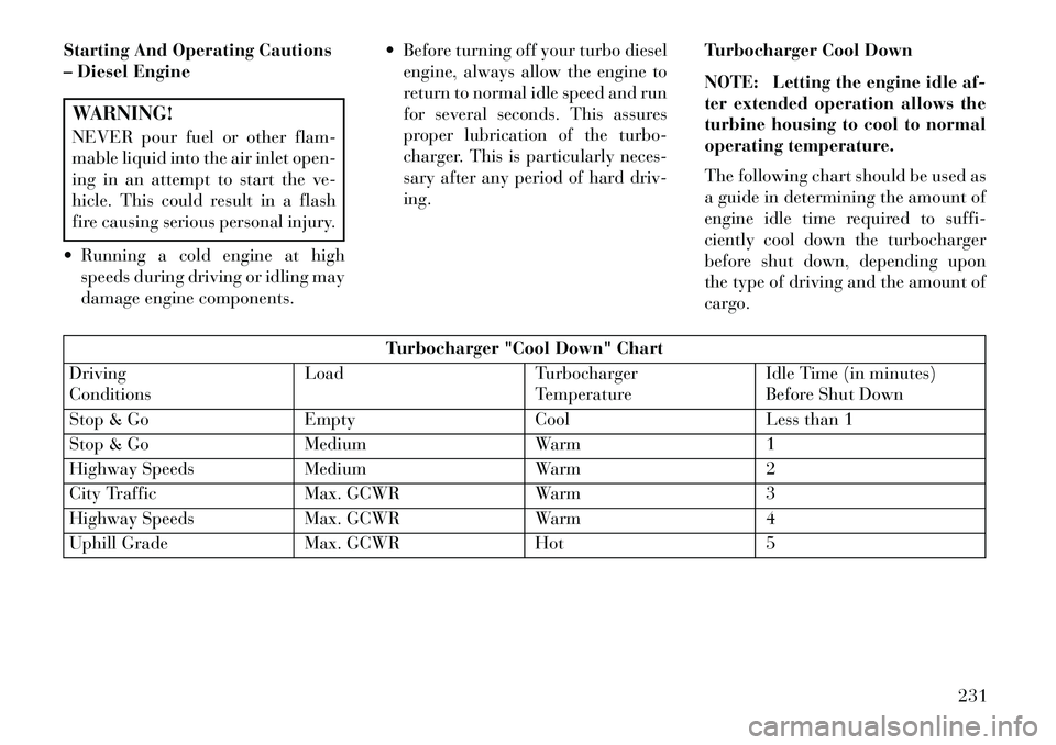
The following chart should be used as
a guide in determining the amount of
engine idle time required to suffi-
ciently cool down the turbocharger
before shut down, depending upon
the type of driving and the amount of
cargo.
Turbocharger "Cool Down" Chart
Driving
Conditions Load Turbocharger
TemperatureIdle Time (in minutes)
Before Shut Down
Stop & Go EmptyCoolLess than 1
Stop & Go MediumWarm1
Highway Speeds MediumWarm2
City Traffic Max. GCWRWarm3
Highway Speeds Max. GCWRWarm4
Uphill Grade Max. GCWRHot5
231
Page 239 of 360
LOCK/OFF position, and once re-
moved, the shift lever is locked in
PARK.
NOTE: If a malfunction occurs,
the system will trap the key fob in
the ignition switch to warn you
that this safety feature is inoper-
able. The engine can be started
and stopped but the key fob cannot
be removed until you obtain ser-
vice.
BRAKE/TRANSMISSION
SHIFT INTERLOCK
SYSTEM
This vehicle is equipped with a Brake
Transmission Shift Interlock System
(BTSI) that holds the shift lever in the
PARK position unless the brakes are
applied. To move the shift lever out of
PARK, the ignition switch must be
turned to the ON/RUN position (en-
gine running or not) and the brake
pedal must be pressed.SIX-SPEED AUTOMATIC
TRANSMISSION
The shift lever position display (lo-
cated in the instrument cluster) indi-
cates the transmission gear range. You
must press the brake pedal to move
the shift lever out of PARK (Refer to
Brake/Transmission Shift Interlock
System in this section). To drive,
move the shift lever from PARK or
NEUTRAL to the DRIVE position.
The electronically-controlled trans-
mission provides a precise shift sched-
ule. The transmission electronics are
self-calibrating; therefore, the first
few shifts on a new vehicle may be
somewhat abrupt. This is a normal
condition, and precision shifts will de-
velop within a few hundred kilome-
ters.
Only shift from DRIVE to PARK or
REVERSE when the accelerator
pedal is released and the vehicle is
stopped. Be sure to keep your foot on
the brake pedal when shifting be-
tween these gears.
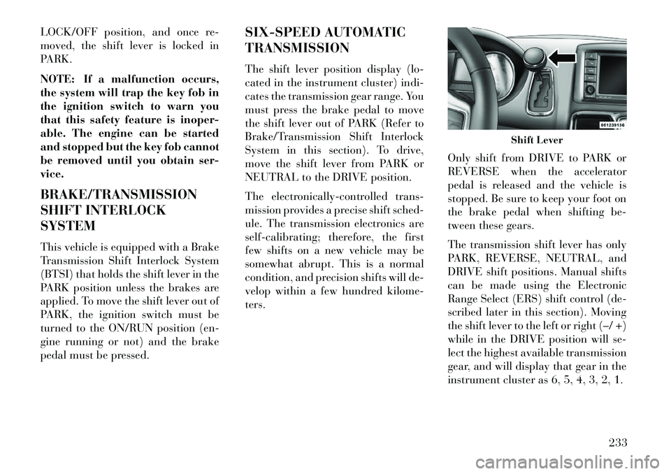
The transmission shift lever has only
PARK, REVERSE, NEUTRAL, and
DRIVE shift positions. Manual shifts
can be made using the Electronic
Range Select (ERS) shift control (de-
scribed later in this section). Moving
the shift lever to the left or right (–/ +)
while in the DRIVE position will se-
lect the highest available transmission
gear, and will display that gear in the
instrument cluster as 6, 5, 4, 3, 2, 1.
Shift Lever
233
Page 241 of 360
WARNING!(Continued)
Allowing children to be in a ve- hicle unattended is dangerous for
a number of reasons. A child or
others could be seriously or fa-
tally injured. Children should be
warned not to touch the parking
brake, brake pedal or the shift
lever.
Do not leave the key fob in or near
the vehicle. A child could operate
power windows, other controls, or
move the vehicle.CAUTION!
Before moving the shift lever outof PARK, you must turn the igni-
tion switch from the LOCK/OFF
position to the ON/RUN position,
and also press the brake pedal.
Otherwise, damage to the shift
lever could result.
DO NOT race the engine when
shifting from PARK or NEU-
TRAL into another gear range, as
this can damage the drivetrain. The following indicators should be
used to ensure that you have engaged
the shift lever into the PARK position:
When shifting into PARK, firmly
move the shift lever all the way
forward and to the left until it stops
and is fully seated.
Look at the shift lever position dis- play and verify that it indicates the
PARK position.
With brake pedal released, verify that the shift lever will not move out
of PARK.
REVERSE
This range is for moving the vehicle
backward. Shift into REVERSE only
after the vehicle has come to a com-
plete stop.
NEUTRAL
Use this range when the vehicle is
standing for prolonged periods with
the engine running. The engine may
be started in this range. Apply the parking brake and shift the transmis-
sion into PARK if you must leave the
vehicle.
WARNING!
Do not coast in NEUTRAL and
never turn off the ignition to coast
down a hill. These are unsafe prac-
tices that limit your response to
changing traffic or road conditions.
You might lose control of the ve-
hicle and have a collision.CAUTION!
Towing the vehicle, coasting, or
driving for any other reason with
the transmission in NEUTRAL can
cause severe transmission damage.
Refer to “Recreational Towing” in
“Starting And Operating” and
“Towing A Disabled Vehicle” in
What To Do In Emergencies” for
further information.
DRIVE
This range should be used for most
city and highway driving. It provides
the smoothest upshifts and down-
shifts, and the best fuel economy. The
235
Page 242 of 360
transmission automatically upshifts
through underdrive first, second,
third, and fourth gears, direct fifth
gear and overdrive sixth gear. The
DRIVE position provides optimum
driving characteristics under all nor-
mal operating conditions.
When frequent transmission shifting
occurs (such as when operating the
vehicle under heavy loading condi-
tions, in hilly terrain, traveling into
strong head winds, or while towing
heavy trailers), use the Electronic
Range Select (ERS) shift control (de-
scribed below) to select a lower gear
range. Under these conditions, using a
lower gear range will improve perfor-
mance and extend transmission life
by reducing excessive shifting and
heat buildup.
During cold temperatures, transmis-
sion operation may be modified de-
pending on engine and transmission
temperature as well as vehicle speed.
This feature improves warm up time
of the engine and transmission to
achieve maximum efficiency. Engage-
ment of the torque converter clutch isinhibited until the transmission fluid
is warm (refer to the “Note” under
“Torque Converter Clutch” in this
section). During extremely cold tem-
peratures (27°C or below), operation
may briefly be limited to third gear
only. Normal operation will resume
once the transmission temperature
has risen to a suitable level.
Transmission Limp Home Mode
Transmission function is monitored
electronically for abnormal condi-
tions. If a condition is detected that
could result in transmission damage,
Transmission Limp Home Mode is ac-
tivated. In this mode, the transmis-
sion remains in third gear regardless
of which forward gear is selected.
PARK, REVERSE, and NEUTRAL
will continue to operate. The Mal-
function Indicator Light (MIL) may
be illuminated. Limp Home Mode al-
lows the vehicle to be driven to an
authorized dealer for service without
damaging the transmission.
In the event of a momentary problem,
the transmission can be reset to regain
all forward gears by performing the
following steps:
1. Stop the vehicle.
2. Shift the transmission into PARK.
3. Turn the engine OFF.
4. Wait approximately 10 seconds.
5. Restart the engine.
6. Shift into the desired gear range. If
the problem is no longer detected, the
transmission will return to normal op-
eration.
NOTE: Even if the transmission
can be reset, we recommend that
you visit your authorized dealer at
your earliest possible conve-
nience. Your authorized dealer has
diagnostic equipment to deter-
mine if the problem could recur.
If the transmission cannot be reset,
authorized dealer service is required.
236
Page 246 of 360

WARNING!
Driving through standing waterlimits your vehicle’s traction ca-
pabilities. Do not exceed 8 km/h
when driving through standing
water.
Driving through standing water
limits your vehicle’s braking ca-
pabilities, which increases stop-
ping distances. Therefore, after
driving through standing water,
drive slowly and lightly press on
the brake pedal several times to
dry the brakes.
Getting water inside your vehi-
cle’s engine can cause it to lock up
and stall out, and leave you
stranded.
Failure to follow these warnings may result in injuries that are se-
rious or fatal to you, your passen-
gers, and others around you. POWER STEERING
The standard power steering system
will give you good vehicle response
and increased ease of maneuverability
in tight spaces. The system will pro-
vide mechanical steering capability if
power assist is lost.
If for some reason the power assist is
interrupted, it will still be possible to
steer your vehicle. Under these condi-
tions, you will observe a substantial
increase in steering effort, especially
at very low vehicle speeds and during
parking maneuvers.
NOTE:
Increased noise levels at the end
of the steering wheel travel are
considered normal and do not
indicate that there is a problem
with the power steering system.
Upon initial start-up in cold weather, the power steering
pump may make noise for a
short amount of time. This is due
to the cold, thick fluid in the
steering system. This noise
should be considered normal, and it does not in any way dam-
age the steering system.
WARNING!
Continued operation with reduced
power steering assist could pose a
safety risk to yourself and others.
Service should be obtained as soon
as possible.CAUTION!
Prolonged operation of the steering
system at the end of the steering
wheel travel will increase the steer-
ing fluid temperature and it should
be avoided when possible. Damage
to the power steering pump may
occur.
POWER STEERING FLUID
CHECK
Checking the power steering fluid
level at a defined service interval is
not required. The fluid should only be
checked if a leak is suspected, abnor-
mal noises are apparent, and/or the
system is not functioning as antici-
pated. Coordinate inspection efforts
through an authorized dealer.
240
Page 249 of 360

WARNING!(Continued)
Pumping of the Anti-Lock Brakes will diminish their effectiveness
and may lead to a collision.
Pumping makes the stopping dis-
tance longer. Just press firmly on
your brake pedal when you need
to slow down or stop.
The Anti-Lock Brake System cannot prevent collisions, includ-
ing those resulting from excessive
speed in turns, following another
vehicle too closely, or hydroplan-
ing.
The capabilities of an ABS- equipped vehicle must never be
exploited in a reckless or danger-
ous manner, which could jeopar-
dize the user’s safety or the safety
of others.
All vehicle wheels and tires must be
the same size and type, and tires must
be properly inflated to produce accu-
rate signals for the computer. ANTI-LOCK BRAKE
WARNING LIGHT
The “Anti-Lock Brake
Warning Light” monitors
the anti-lock brake system.
The light will come on when
the ignition switch is turned to the ON
position and may stay on for as long
as four seconds.
If the “Anti-Lock Brake Warning
Light” remains on or comes on while
driving, it indicates that the anti-lock
portion of the brake system is not
functioning and that service is re-
quired. However, the conventional
brake system will continue to operate
normally if the “Brake Warning
Light” is not on.
If the “Anti-Lock Brake Warning
Light” is on, the brake system should
be serviced as soon as possible to re-
store the benefits of anti-lock brakes.
If the “Anti-Lock Brake Warning
Light” does not come on when the
ignition switch is turned to the ON
position, have the bulb repaired as
soon as possible. If both the “Brake Warning Light”
and the “Anti-Lock Brake Warning
Light” remain on, the ABS and Elec-
tronic Brake Force Distribution
(EBD) systems are not functioning.
Immediate repair to the ABS system is
required. Consult with your autho-
rized dealer service center as soon as
possible.
ELECTRONIC BRAKE
CONTROL SYSTEM (FOR
VERSIONS/MARKETS,
WHERE PROVIDED)
Your vehicle is equipped with an ad-
vanced electronic brake control sys-
tem that includes the Traction Control
System (TCS), Brake Assist System
(BAS) and Electronic Stability Con-
trol (ESC), Trailer Sway Control
(TSC), and Hill Start Assist (HSA).
These systems complement the Anti-
Lock Brake System (ABS) by opti-
mizing the vehicle braking capability
during emergency braking maneu-
vers.
243
Page 250 of 360

TRACTION CONTROL
SYSTEM (TCS) (FOR
VERSIONS/MARKETS,
WHERE PROVIDED)
The Traction Control System (TCS)
monitors the amount of wheel spin of
each of the driven wheels. If wheel
spin is detected, brake pressure is ap-
plied to the slipping wheel(s) and en-
gine power is reduced, to provide en-
hanced acceleration and stability. A
feature of the TCS functions similarly
to a limited-slip differential, and con-
trols the wheel spin across a driven
axle. If one wheel on a driven axle is
spinning faster than the other, the sys-
tem will apply the brake of the spin-
ning wheel. This will allow more en-
gine torque to be applied to the wheel
that is not spinning. This feature re-
mains active even if the ESC is in the
“Partial Off” mode.The “ESC Activation/Malfunction In-
dicator Light” (in the instrument
cluster) will start to flash as soon as
the tires lose traction and the wheels
begin to spin. This indicates that the
TCS is active. If the indicator light
flashes during acceleration, ease up
on the accelerator and apply as little
throttle as possible. Be sure to adapt
your speed and driving to the prevail-
ing road conditions, and do not switch
off the ESC or TCS.
WARNING!
The TCS cannot prevent the
natural laws of physics from act-
ing on the vehicle, nor can it in-
crease the traction afforded.
The TCS cannot prevent colli- sions, including those resulting
from excessive speed in turns, or
hydroplaning.
The capabilities of a TCS- equipped vehicle must never be
exploited in a reckless or danger-
ous manner, which could jeopar-
dize the user's safety or the safety
of others. BRAKE ASSIST SYSTEM
(BAS) (FOR VERSIONS/
MARKETS, WHERE
PROVIDED)
The Brake Assist System (BAS) is de-
signed to optimize the vehicle’s brak-
ing capability during emergency
braking maneuvers. The system de-
tects an emergency braking situation
by sensing the rate and amount of
brake application, and then applies
optimum pressure to the brakes. This
can help reduce braking distances.
The BAS complements the ABS. Ap-
plying the brakes very quickly results
in the best BAS assistance. To receive
the benefit of the system, you must
apply continuous braking pressure
during the stopping sequence. Do not
reduce brake pedal pressure unless
braking is no longer desired. Once the
brake pedal is released, the BAS is
deactivated.
244
Page 267 of 360

WARNING!
Overloading of your tires is danger-
ous. Overloading can cause tire
failure, affect vehicle handling, and
increase your stopping distance.
Use tires of the recommended load
capacity for your vehicle. Never
overload them.
TIRE ROTATION
RECOMMENDATIONS
Tires on the front and rear axles of
vehicles operate at different loads and
perform different steering, driving,
and braking functions. For these rea-
sons, they wear at unequal rates.
These effects can be reduced by
timely rotation of tires. The benefits
of rotation are especially worthwhile
with aggressive tread designs such as
those on all season type tires. Rotation
will increase tread life, help to main-
tain mud, snow, and wet traction lev-
els, and contribute to a smooth, quiet
ride.
Refer to the “Maintenance Schedule”
for the proper maintenance intervals. The reasons for any rapid or unusual
wear should be corrected prior to ro-
tation being performed.
TIRE PRESSURE
MONITOR SYSTEM
(TPMS)
The TPMS will warn the driver of a
low tire pressure based on the cold
inflation tire pressure requirements
found on the tire placard located on
the driver's-side B-pillar.
The tire pressure will vary with tem-
perature by about 0.07 BAR for every
7°C. This means that when the out-
side temperature decreases, the tire
pressure will decrease. Tire pressure
should always be set based on cold
inflation tire pressure. This is defined
as the tire pressure after a vehicle has
not been driven for more than three
hours - and in outside ambient tem-
perature.
Refer to “Tires – General
Information” in “Starting and Op-
erating” for information on how to
properly inflate the vehicle’s tires.
The tire pressure will also increase as the vehicle is driven - this is normal
and there should be no adjustment for
this increased pressure.
The TPMS will warn the driver of a
low tire pressure if the tire pressure
falls below the low pressure warning
threshold for any reason, including
low temperature effects, or natural air
pressure loss through the tire.
The TPMS will continue to warn the
driver of low tire pressure as long as
the condition exists, and will not turn
off until the tire pressure is at or above
recommended cold tire placard pres-
sure. Once the low tire pressure warn-
ing has been illuminated, the tire
pressure must be increased to the rec-
ommended cold tire placard pressure
in order for the “Tire Pressure Moni-
toring Telltale Light” to be turned off.
The system will automatically update
and the “Tire Pressure Monitoring
Telltale Light” will extinguish once
the updated tire pressures have been
received. The vehicle may need to be
driven for up to 20 minutes above
24 km/h to receive this information.
261
Page 300 of 360

NOTE: Press the "ESC Off"
switch, to place the Electronic Sta-
bility Control (ESC) system in
"Partial Off" mode before rocking
the vehicle. Refer to “Electronic
Brake Control System” in “Start-
ing and Operating” for further in-
formation.Once the vehicle has
been freed, press the "ESC Off"
switch again to restore "ESC On"
mode.
CAUTION!
When “rocking” a stuck vehicleby shifting between DRIVE and
REVERSE, do not spin the
wheels faster than 24 km/h, or
drivetrain damage may result.
Revving the engine or spinning
the wheels too fast may lead to
transmission overheating and
failure. It can also damage the
tires. Do not spin the wheels
above 48 km/h while in gear (no
transmission shifting occurring).
WARNING!
Fast spinning tires can be danger-
ous. Forces generated by excessive
wheel speeds may cause damage, or
even failure, of the axle and tires. A
tire could explode and injure some-
one. Do not spin your vehicle's
wheels faster than 48 km/h or for
longer than 30 seconds continu-
ously without stopping when you
are stuck and do not let anyone
near a spinning wheel, no matter
what the speed.
294
Page 308 of 360
CAUTION!(Continued)
Car maintenance should be done at a LANCIA Dealership. For
routine and minor maintenance
operations you wish to carry out
yourself, we do recommend you
have the proper equipment,
genuine LANCIA spare parts and
the necessary fluids; do not how-
ever carry out these operations if
you have no experience.
Your vehicle has been built with improved fluids that protect the
performance and durability of
your vehicle and also allow ex-
tended maintenance intervals. Do
not use chemical flushes in these
components as the chemicals can
damage your engine, transmis-
sion, power steering or air condi-
tioning. Such damage is not cov-
ered by the New Vehicle Limited
Warranty. If a flush is needed be-
cause of component malfunction,
use only the specified fluid for the
flushing procedure. ENGINE OIL
Checking Oil Level
To assure proper engine lubrication,
the engine oil must be maintained at
the correct level. Check the oil level at
regular intervals, such as every fuel
stop.
The best time to check the engine oil
level is about five minutes after a fully
warmed engine is shut off or before
starting the engine after it has sat
overnight.
Checking the oil while the vehicle is
on level ground will improve the ac-
curacy of the oil level readings. Main-
tain the oil level between the MIN and
MAX markings on the dipstick. Add-
ing one quart of oil when the reading
is at the MIN mark will result in a
MAX reading on these engines.
CAUTION!
Overfilling or underfilling will
cause oil aeration or loss of oil pres-
sure. This could damage your en-
gine.CAUTION!
Car maintenance should be done at
a LANCIA Dealership. For routine
and minor maintenance operations
you wish to carry out yourself, we
do recommend you have the proper
equipment, genuine LANCIA spare
parts and the necessary fluids; do
not however carry out these opera-
tions if you have no experience.
Change Engine Oil – All Engines
The oil change indicator system will
remind you that it is time to take your
vehicle in for scheduled maintenance.
Refer to “Maintenance Schedule” for
further information on this system.
302