display Lancia Voyager 2014 Owner handbook (in English)
[x] Cancel search | Manufacturer: LANCIA, Model Year: 2014, Model line: Voyager, Model: Lancia Voyager 2014Pages: 364, PDF Size: 3.49 MB
Page 19 of 364
A WORD ABOUT YOUR
KEYS
Your vehicle is equipped with a key-
less ignition system. This system con-
sists of a Key Fob with Remote Key-
less Entry (RKE) transmitter and a
Wireless Ignition Node (WIN) with
integral ignition switch. You can in-
sert the Key Fob into the ignition
switch with either side up.
Keyless Enter-N-Go™ Feature for
(versions/markets where provided)
This vehicle may be equipped with
the Keyless Enter-N-Go™ feature, re-
fer to Starting Procedures in Starting
And Operating for further informa-
tion.
IGNITION NODE MODULE
(IGNM) — (for
versions/markets where
provided)
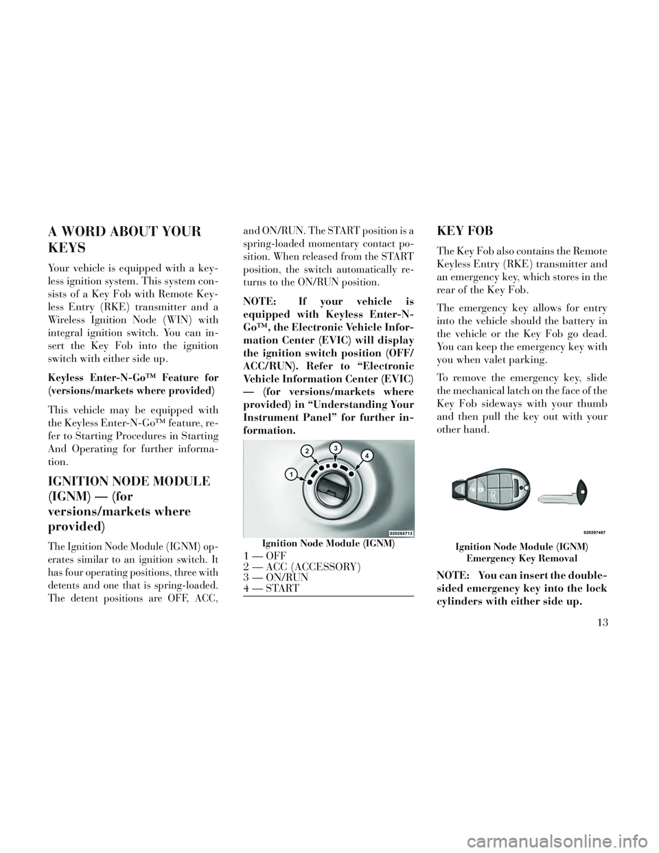
The Ignition Node Module (IGNM) op-
erates similar to an ignition switch. It
has four operating positions, three with
detents and one that is spring-loaded.
The detent positions are OFF, ACC,and ON/RUN. The START position is a
spring-loaded momentary contact po-
sition. When released from the START
position, the switch automatically re-
turns to the ON/RUN position.
NOTE: If your vehicle is
equipped with Keyless Enter-N-
Go™, the Electronic Vehicle Infor-
mation Center (EVIC) will display
the ignition switch position (OFF/
ACC/RUN). Refer to “Electronic
Vehicle Information Center (EVIC)
— (for versions/markets where
provided) in “Understanding Your
Instrument Panel” for further in-
formation.
KEY FOB
The Key Fob also contains the Remote
Keyless Entry (RKE) transmitter and
an emergency key, which stores in the
rear of the Key Fob.
The emergency key allows for entry
into the vehicle should the battery in
the vehicle or the Key Fob go dead.
You can keep the emergency key with
you when valet parking.
To remove the emergency key, slide
the mechanical latch on the face of the
Key Fob sideways with your thumb
and then pull the key out with your
other hand.
NOTE: You can insert the double-
sided emergency key into the lock
cylinders with either side up.
Ignition Node Module (IGNM)
1 — OFF
2 — ACC (ACCESSORY)
3 — ON/RUN
4—STARTIgnition Node Module (IGNM)
Emergency Key Removal
13
Page 50 of 364
system whenever the ignition switch is
in the START or ON/RUN position. If
the key is in the LOCK position, in the
ACC position, or not in the ignition,
the Active Hood system is not on and
the Active Hood will not deploy.
The EPPM contains a backup power
supply system that may deploy the
actuators even if the battery loses
power or it becomes disconnected
prior to deployment.
Service Active Hood System
If the EPPM has deployed the Active
Hood, or if it detects a malfunction in
any part of the system, it turns on the
Air Bag Warning Light and it will
display the “SERVICE ACTIVE
HOOD” message in the Electronic Ve-
hicle Information Center (EVIC), for
versions/markets, where provided. A
single chime will sound if the Air Bag
Warning Light comes on again after
initial startup. It also includes diag-
nostics that will illuminate the Air Bag
Warning Light if a malfunction is
noted that could affect the Active
Hood system. The diagnostics also re-
cord the nature of the malfunction. Ifthe Air Bag Warning Light is illumi-
nated, or if “SERVICE ACTIVE
HOOD” appears in the EVIC, see
your authorized dealer.
In the event of an Active Hood deploy-
ment, the vehicle should be serviced
by an authorized dealer. The hood
hinges must be serviced and the ac-
tuator assemblies replaced to restore
system functionality.
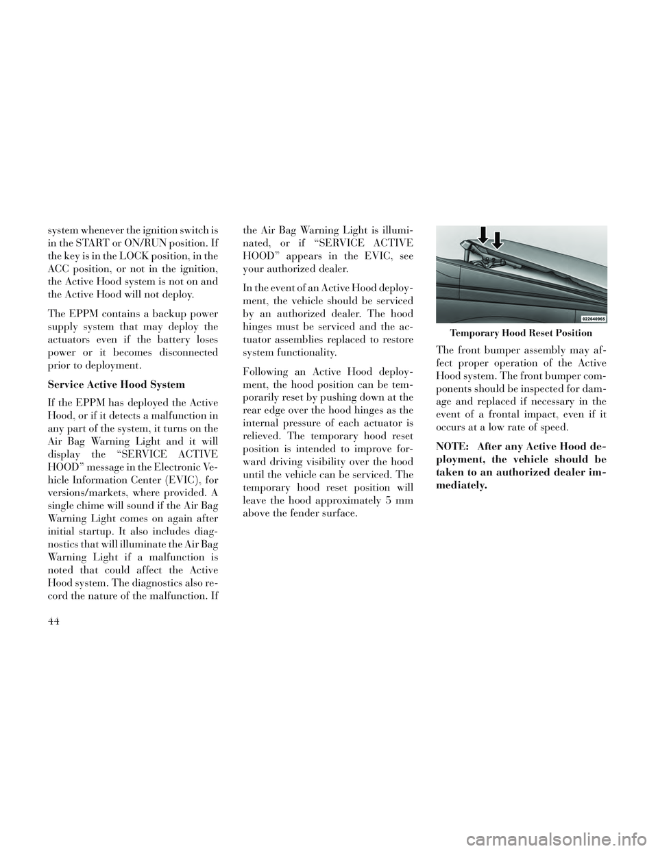
Following an Active Hood deploy-
ment, the hood position can be tem-
porarily reset by pushing down at the
rear edge over the hood hinges as the
internal pressure of each actuator is
relieved. The temporary hood reset
position is intended to improve for-
ward driving visibility over the hood
until the vehicle can be serviced. The
temporary hood reset position will
leave the hood approximately 5 mm
above the fender surface.
The front bumper assembly may af-
fect proper operation of the Active
Hood system. The front bumper com-
ponents should be inspected for dam-
age and replaced if necessary in the
event of a frontal impact, even if it
occurs at a low rate of speed.
NOTE: After any Active Hood de-
ployment, the vehicle should be
taken to an authorized dealer im-
mediately.
Temporary Hood Reset Position
44
Page 84 of 364
RAIN SENSING WIPERS (for versions/markets,where provided) ....................... .134
TILT/TELESCOPING STEERING COLUMN .....135
ADJUSTABLE PEDALS (for versions/markets, where provided) .............................. .135
ELECTRONIC SPEED CONTROL ............136
TO ACTIVATE ......................... .137
TO SET A DESIRED SPEED ...............137
TO DEACTIVATE ...................... .137
TO RESUME SPEED .................... .137
TO VARY THE SPEED SETTING ...........137
TO ACCELERATE FOR PASSING ...........138
PARKSENSE® REAR PARK ASSIST (for versions/markets, where provided) ...........138
PARK ASSIST SENSORS .................138
PARKSENSE® WARNING DISPLAY .........138
PARKSENSE® DISPLAY .................139
ENABLING/DISABLING PARKSENSE® ......140
SERVICE THE PARKSENSE® REAR PARK ASSIST SYSTEM ...................... .140
CLEANING THE PARK ASSIST SYSTEM .....141
PARKSENSE® SYSTEM USAGE PRECAUTIONS ........................ .141
PARKVIEW® REAR BACK UP CAMERA (for versions/markets, where provided) ...........143
TURNING PARKVIEW® ON OR OFF — WITH NAVIGATION/MULTIMEDIA RADIO .........144
78
Page 96 of 364
Voice Command Button
Actual button location may
vary with radio. The indi-
vidual buttons are described
in the “Operation” section.
The Uconnect® Phone can be used
with Hands-Free Profile certified
Bluetooth® mobile phones. Some
phones may not support all the
Uconnect® Phone features. Refer to
your mobile service provider or the
phone manufacturer for details.
The Uconnect® Phone is fully inte-
grated with the vehicle's audio sys-
tem. The volume of the Uconnect®
Phone can be adjusted either from the
radio volume control knob or from the
steering wheel radio control, if so
equipped.
The radio display will be used for
visual prompts from the Uconnect®
Phone such as CELL or caller ID on
certain radios.
COMPATIBLE PHONES
* The Uconnect® Phone requires a
mobile phone equipped with the
Bluetooth® “Hands-Free Profile”,
version 1.0 or higher.
See Uconnect® website for supported
phones.
www.UconnectPhone.com
To find the list of compatible phones
navigate through the following
menus:
Select model year for the vehicle
Select type of the vehicle
In the getting started tab, selectcompatible phones
OPERATION
Voice commands can be used to oper-
ate the Uconnect® Phone and to navi-
gate through the Uconnect® Phone
menu structure. Voice commands are
required after most Uconnect® Phone
prompts. You will be prompted for a
specific command and then guided
through the available options. Prior to giving a voice command,
one must wait for the beep, which
follows the “Ready” prompt or an-
other prompt.
For certain operations, compound commands can be used. For ex-
ample, instead of saying “Setup”
and then “Phone Pairing”, the fol-
lowing compound command can be
said: “Setup Phone Pairing”.
For each feature explanation in this section, only the compound form of
the voice command is given. You
can also break the commands into
parts and say each part of the com-
mand when you are asked for it.
For example, you can use the com-
pound form voice command
“Phonebook New Entry”, or you
can break the compound form
command into two voice com-
mands: “Phonebook” and “New
Entry”. Please remember, the
Uconnect® Phone works best when
you talk in a normal conversational
tone, as if speaking to someone sit-
ting a few meters away from you.
90
Page 98 of 364
Dial By Saying A Number
Press the
button to begin.
After the “Ready” prompt and the following beep, say “Dial.”
The system will prompt you to say the number you want to call.
For example, you can say “151-1234-5555.”
The Uconnect® Phone will confirm the phone number and then dial.
The number will appear in the dis-
play of certain radios.
Call By Saying A Name
Press the
button to begin.
After the “Ready” prompt and the following beep, say “Call.”
The system will prompt you to say the name of the person you want to
call.
After the “Ready” prompt and the following beep, say the name of the
person you want to call. For ex-
ample, you can say “John Doe”,
where John Doe is a previously stored name entry in the
Uconnect® Phonebook or down-
loaded phonebook. To learn how to
store a name in the phonebook ,
refer to “Add Names to Your
Uconnect® Phonebook”.
The Uconnect® Phone will confirm the name and then dial the corre-
sponding phone number, which
may appear in the display of certain
radios.
Add Names To Your Uconnect®
Phonebook
NOTE: Adding names to the
Uconnect® Phonebook is recom-
mended when the vehicle is not in
motion.
Press the
button to begin.
After the “Ready” prompt and the following beep, say “Phonebook
New Entry”.
When prompted, say the name of the new entry. Use of long names
helps the Voice Command and it is recommended. For example, say
“Robert Smith” or “Robert” in-
stead of “Bob”.
When prompted, enter the number designation (e.g., “Home”,
“Work”, “Mobile”, or “Other”).
This will allow you to store multiple
numbers for each phonebook entry,
if desired.
When prompted, recite the phone number for the phonebook entry
that you are adding.
After you are finished adding an entry
into the phonebook, you will be given
the opportunity to add more phone
numbers to the current entry or to
return to the main menu.
The Uconnect® Phone will allow you
to enter up to 32 names in the phone-
book with each name having up to
four associated phone numbers and
designations. Each language has a
separate 32-name phonebook acces-
sible only in that language. In addi-
tion, for versions/markets, where pro-
vided, and supported by your phone,
92
Page 104 of 364
You can use your Uconnect® Phone to
access a voice mail system or an auto-
mated service, such as a paging ser-
vice or automated customer service.
Some services require immediate re-
sponse selection. In some instances,
that may be too quick for use of the
Uconnect® Phone.
When calling a number with your
Uconnect® Phone that normally re-
quires you to enter in a touch-tone
sequence on your mobile phone key-
pad, you can press the
button
and say the sequence you wish to en-
ter followed by the word “Send”. For
example, if required to enter your PIN
followed with a hash, (3746#),you
can press the
button and say,
“3746#Send”. Saying a number, or
sequence of numbers, followed by
“Send”, is also to be used for navigat-
ing through an automated customer
service center menu structure, and to
leave a number on a pager.
You can also send stored Uconnect®
Phonebook entries as tones for fast
and easy access to voice mail and
pager entries. To use this feature, dial
the number you wish to call and then press the
button and say “Send.”
The system will prompt you to enter
the name or number and say the name
of the phonebook entry you wish to
send. The Uconnect® Phone will then
send the corresponding phone num-
ber associated with the phonebook
entry, as tones over the phone.
NOTE:
You may not hear all of the tones due to mobile phone network
configurations; this is normal.
Some paging and voice mail sys- tems have system time out set-
tings that are too short and may
not allow the use of this feature.
BARGE IN — OVERRIDING
PROMPTS
The “Voice Command” button can be
used when you wish to skip part of a
prompt and issue your voice com-
mand immediately. For example, if a
prompt is asking “Would you like to
pair a phone, clear a…,” you could
press the
button and say, “Pair a Phone” to select that option without
having to listen to the rest of the voice
prompt.
TURNING CONFIRMATION
PROMPTS ON/OFF
Turning confirmation prompts off
will stop the system from confirming
your choices (e.g., the Uconnect®
Phone will not repeat a phone number
before you dial it).
Press the
button to begin.
After the “Ready” prompt and the following beep, say:
“Setup Confirmations Prompts On”
“Setup Confirmations Prompts Off”
PHONE AND NETWORK
STATUS INDICATORS
If available on the radio and/or on a
premium display such as the instru-
ment panel cluster, and supported by
your mobile phone, the Uconnect®
Phone will provide notification to in-
form you of your phone and network
98
Page 132 of 364
SETTING MEMORY
POSITIONS AND LINKING
RKE TRANSMITTER TO
MEMORY
NOTE: Each time the SET (S) but-
ton and a numbered button (1 or 2)
is pressed, you erase the memory
settings for that button and store a
new one.
1. Insert the ignition key and turn the
ignition switch to the ON position.
2. Press the driver door MEMORY
button number 1 if you are setting the
memory for driver 1, or button num-
ber 2 if you are setting the memory for
driver 2. The system will recall any
stored settings. Wait for the system to
complete the memory recall before
continuing to Step 3.
3. Adjust the driver's seat, recliner,
and driver's side-view mirror to the
desired positions.
4. Adjust the brake and accelerator
pedals to the desired positions.5. Turn on the radio and set the radio
station presets (up to 10 AM and 10
FM stations can be set).
6. Turn the ignition switch to the
OFF position and remove the key.
7. Press and release the SET (S) but-
ton located on the driver's door.
8. Within five seconds, press and re-
lease MEMORY button 1 or 2 on the
driver's door. The next step must be
performed within 5 seconds if you
desire to also use a RKE transmitter to
recall memory positions.
9. Select “Remote Linked to
Memory” in the Electronic Vehicle In-
formation Center (EVIC) and enter
“Yes”. Refer to “Electronic Vehicle In-
formation Center (EVIC)/Customer-
Programmable Features” in “Under-
standing Your Instrument Panel” for
further information.
10. Press and release the LOCK but-
ton on one of the RKE transmitters.
11. Insert the ignition key and turn
the ignition switch to the ON position.12. Repeat the above steps to set the
next Memory position using the other
numbered Memory button or to link
another RKE transmitter to memory.
Memory Position Recall
NOTE: The vehicle must be in
PARK to recall memory positions.
If a recall is attempted when the
vehicle is not in PARK, a message
will be displayed in the EVIC.
To recall the memory settings for
driver one, press MEMORY button 1
on the driver's door or the UNLOCK
button on the RKE transmitter linked
to memory position 1.
To recall the memory setting for
driver two, press MEMORY button 2
on the driver's door or the UNLOCK
button on the RKE transmitter linked
to Memory Position 2.
A recall can be cancelled by pressing
any of the MEMORY buttons on the
driver's door during a recall (S, 1, or
2). When a recall is cancelled, the
driver's seat, outside mirrors, and the
126
Page 142 of 364
The switch is located on the left side of
the steering column.
Press the switch forward to move the
pedals forward (toward the front of
the vehicle).
Press the switch rearward to move the
pedals rearward (toward the driver).
The pedals can be adjusted with theignition OFF.
The pedals cannotbe adjusted
when the vehicle is in REVERSE or
when the Electronic Speed Control
System is on. The following mes-
sages will be displayed on vehicles
equipped with the Electronic Ve-
hicle Information System (EVIC) if
the pedals are attempted to be ad-
justed when the system is locked
out (“Adjustable Pedal Disabled — Cruise Control Engaged” or “Ad-
justable Pedal Disabled — Vehicle
In Reverse”.
NOTE:
Always adjust the pedals to a po- sition that allows full pedal
travel.
Further small adjustments may be necessary to find the best pos-
sible seat/pedal position.
CAUTION!
Do not place any article under the
adjustable pedals or impede its
ability to move, as it may cause
damage to the pedal controls. Pedal
travel may become limited if move-
ment is stopped by an obstruction
in the adjustable pedal's path.
WARNING!
Do not adjust the pedals while the
vehicle is moving. You could lose
control and have an accident. Al-
ways adjust the pedals while the
vehicle is parked.
ELECTRONIC SPEED
CONTROL
When engaged, the Electronic Speed
Control takes over accelerator opera-
tions at speeds greater than 40 km/h.
NOTE: In order to ensure proper
operation, the Electronic Speed
Control System has been designedAdjustable Pedal Switch
Electronic Speed Control Buttons
1 — ON/OFF 2 — RES +
4 — CANCEL 3 — SET -
136
Page 144 of 364
speed. Each subsequent tap of the
button results in a decrease of
1.6 km/h.
TO ACCELERATE FOR
PASSING
Press the accelerator as you would
normally. When the pedal is released,
the vehicle will return to the set speed.
Using Electronic Speed Control
On Hills
The transmission may downshift on
hills to maintain the vehicle set speed.
NOTE: The Electronic Speed
Control system maintains speed up
and down hills. A slight speed
change on moderate hills is nor-
mal.
On steep hills, a greater speed loss or
gain may occur so it may be prefer-
able to drive without Electronic Speed
Control.
WARNING!
Electronic Speed Control can be
dangerous where the system cannot
maintain a constant speed. Your ve-
hicle could go too fast for the con-
ditions, and you could lose control
and have an accident. Do not use
Electronic Speed Control in heavy
traffic or on roads that are winding,
icy, snow-covered or slippery.
PARKSENSE® REAR
PARK ASSIST (for
versions/markets, where
provided)
The ParkSense® Rear Park Assist sys-
tem provides visual and audible indi-
cations of the distance between the rear
fascia and a detected obstacle when
backing up, e.g. during a parking ma-
neuver. Refer to ParkSense® System
Usage Precautions for limitations of
this system and recommendations.
ParkSense® will retain the last system
state (enabled or disabled) from the
last ignition cycle when the ignition is
changed to the ON/RUN position.
ParkSense® can be active only when
the shift lever is in REVERSE. If
ParkSense® is enabled at this shift
lever position, the system will remain
active until the vehicle speed is in-
creased to approximately 11 km/h or
above. The system will become active
again if the vehicle speed is decreased
to speeds less than approximately
9 km/h.
PARK ASSIST SENSORS
The four Park Assist sensors, located
in the rear fascia/bumper, monitor the
area behind the vehicle that is within
the sensors’ field of view. The sensors
can detect obstacles from approxi-
mately 30 cm up to 200 cm from the
rear fascia/bumper in the horizontal
direction, depending on the location,
type and orientation of the obstacle.
PARKSENSE® WARNING
DISPLAY
The ParkSense® Warning screen will
only be displayed if Sound and Dis-
play is selected from the Customer-
Programmable Features section of the
Electronic Vehicle Information Center
138
Page 145 of 364
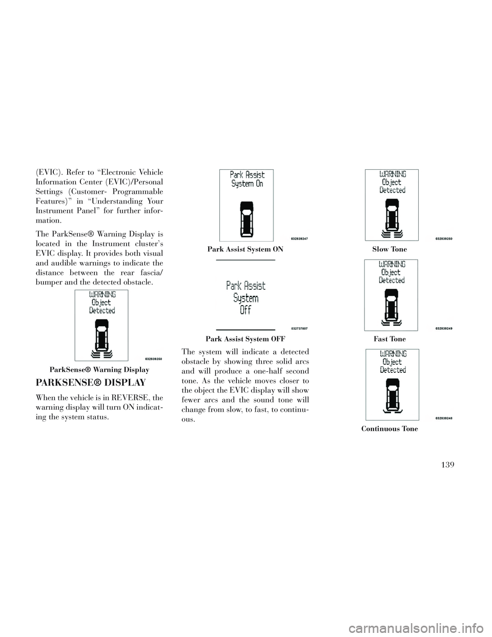
(EVIC). Refer to “Electronic Vehicle
Information Center (EVIC)/Personal
Settings (Customer- Programmable
Features)” in “Understanding Your
Instrument Panel” for further infor-
mation.
The ParkSense® Warning Display is
located in the Instrument cluster’s
EVIC display. It provides both visual
and audible warnings to indicate the
distance between the rear fascia/
bumper and the detected obstacle.
PARKSENSE® DISPLAY
When the vehicle is in REVERSE, the
warning display will turn ON indicat-
ing the system status.The system will indicate a detected
obstacle by showing three solid arcs
and will produce a one-half second
tone. As the vehicle moves closer to
the object the EVIC display will show
fewer arcs and the sound tone will
change from slow, to fast, to continu-
ous.
ParkSense® Warning Display
Park Assist System ON
Park Assist System OFF
Slow Tone
Fast Tone
Continuous Tone
139