lock Lancia Ypsilon 2002 Owner handbook (in English)
[x] Cancel search | Manufacturer: LANCIA, Model Year: 2002, Model line: Ypsilon, Model: Lancia Ypsilon 2002Pages: 191, PDF Size: 2.45 MB
Page 60 of 191

57
G
In the case of failure, although the
anti-locking system is no longer avail-
able, the car braking capacity is not
interfered with.
If you have never driven a car with
ABS it is advised to familiarise by
making a few preliminary trials on
slippery ground, obviously maintain-
ing safety conditions and respecting
the Highway Code of the country
where you are travelling. Before start-
ing, read carefully the notes below.
The advantage of ABS as compared
with the traditional system is that it
permits maximum manoeuvrability
even when pressing the brakes right
down on roads with poor grip, pre-
venting the wheels from locking.
However, this does not mean that
with ABS the braking distance is al-
ways reduced. For example, on soft
gravel surfaces or fresh snow on a
slippery surface the distance could in-
crease.In order to get the best out of the
anti-lock system when necessary, fol-
low these hints.
If the ABS triggers it
means that the car is
reaching the limit of ad-
herence between the tyres and the
road surface. Slow down to adapt
the speed to the road grip.
ABS exploits the avail-
able grip, but it is not able
to increase it. Therefore
drive carefully on slippery surfaces
and do not take undue risks.
If there is a system fail-
ure, indicated by warning
light>lighting up on the
instrument panel, drive slowly and
go immediately to a LANCIA Deal-
ership to have the system checked.
When braking round a bend be very
careful, even with the aid of ABS.
However, the most important advice
is the following:
When the ABS switches
on and you feel the pedal
throbbing, no not lighten
the pressure, but keep the pedal
pressed well down and do not
worry. In this way you will be able
to stop within the minimum dis-
tance possible, according to the
road surface.
Following these instructions you will
be always have the best braking con-
ditions.
4C001-067 ING 11-03-2008 11:57 Pagina 57
Page 61 of 191

58
G
FRONT AND SIDE
AIRBAGS
FRONT AIRBAGS (fig. 85)
Description and operation
The front airbag (driver and pas-
senger) is a safety device which is im-
mediately triggered in the event of a
front impact.
It consists of an instantly inflatable
bag housed in a special compartment
located:
– in the centre of the steering wheel
on the driver’s side;
– in the dashboard on the passen-
ger’s side (larger bag).
The front airbag (driver and pas-
senger) is a device which protects the
occupants of the car during a head-on
collision of a medium-high degree.
The system was designed to protect
from injury caused by the body crash-
ing to the steering wheel or the dash-
board. IMPORTANTCars fitted with ABS
must always be fitted with the wheel
rims, tyres and brake linings of the
type and make recommended by the
Manufacturer.
The system also includes the EBD
electronic brake correction (Electronic
Brake Distributor) which, through the
control unit and the ABSsensors fur-
ther enhances the braking system.
The car is fitted with an
electronic brake distribu-
tor (EBD). If warning lights
>andxlight up simultaneously
when the engine is running, this
indicates an EBD fault. This
means that violent braking could
cause early locking of the rear
wheels causing the car to skid.
Drive very carefully to the nearest
LANCIA Dealership to have the
system checked.
If only warning light >
switches on when the en-
gine is running, this usu-
ally indicates an ABS fault. In such
cases the braking system is still ef-
ficient, although the anti-locking
device does not function. The EBD
system may also be less efficient.
Go to a LANCIA Dealership imme-
diately, taking care not to brake
suddenly, and have the system
checked.
If the xbrake fluid low
warning light comes on,
stop the car immediately
and contact the nearest LANCIA
Dealership. Fluid leaks from the
hydraulic system, can compromise
brake system operation, both tra-
ditional systems and systems with
ABS.
4C001-067 ING 11-03-2008 11:57 Pagina 58
Page 70 of 191

67
G
Only change the fuel filler cap with
a genuine spare part in order not to
compromise the petrol fume recovery
system.FUEL TANK CAP
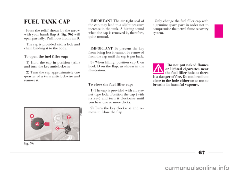
Press the relief shown by the arrow
with your hand; flapA (fig. 96)will
open partially. Pull it out from rim B.
The cap is provided with a lock and
chain binding it to the body.
To open the fuel filler cap:
1)Hold the cap in position (still)
and turn the key anticlockwise.
2)Turn the cap approximately one
quarter of a turn anticlockwise and
remove it.IMPORTANTThe air-tight seal of
the cap may lead to a slight pressure
increase in the tank. A hissing sound
when the cap is removed is, therefore,
quite normal.
IMPORTANTTo prevent the key
from being lost it cannot be removed
from the cap until the cap is put back.
3)When filling, position cap Con
hookDon the flap, as shown in the
illustration.
To close the fuel filler cap:
1)The cap is provided with a bayo-
net type lock. Position the cap (with
its key) and turn it clockwise until
you hear one or more clicks.
2)Turn the key clockwise and re-
move it. Close the flap.Do not put naked flames
or lighted cigarettes near
the fuel filler hole as there
is a danger of fire. Do not bend too
close to the hole either so as not to
breathe in harmful vapours.
fig. 96
P4C00381
4C001-067 ING 11-03-2008 11:57 Pagina 67
Page 74 of 191

71
G
HANDBRAKE
The handbrake lever is situated be-
tween the two front seats.
To put the handbrake on, pull it up-
wards until the vehicle is blocked;
normally four or five clicks are suffi-
cient on flat ground, whereas seven or
eight might be necessary when park-
ing on steep slopes with the vehicle
laden.
IMPORTANTIf this is not the case,
take the car to a LANCIA Dealer-
shipto have the handbrake adjusted.
When the ignition key is turned to
MARand the handbrake pulled up,
the warning lamp xwill light up on
the instrument panel.To release the handbrake:
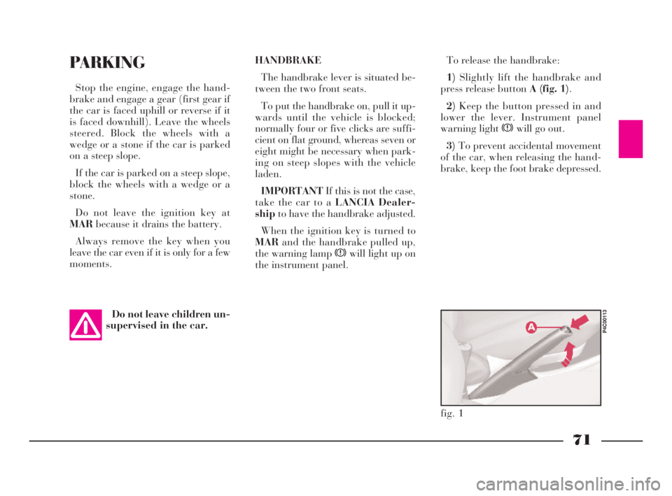
1)Slightly lift the handbrake and
press release button A (fig. 1).
2)Keep the button pressed in and
lower the lever. Instrument panel
warning light xwill go out.
3)To prevent accidental movement
of the car, when releasing the hand-
brake, keep the foot brake depressed.PARKING
Stop the engine, engage the hand-
brake and engage a gear (first gear if
the car is faced uphill or reverse if it
is faced downhill). Leave the wheels
steered. Block the wheels with a
wedge or a stone if the car is parked
on a steep slope.
If the car is parked on a steep slope,
block the wheels with a wedge or a
stone.
Do not leave the ignition key at
MARbecause it drains the battery.
Always remove the key when you
leave the car even if it is only for a few
moments.
Do not leave children un-
supervised in the car.
fig. 1
P4C00113
4C068-089 ING 11-03-2008 11:59 Pagina 71
Page 82 of 191

79
G
DRIVING IN THE MOUNTAINS
– When driving downhill use the en-
gine braking effect by engaging a low
gear so as not to overheat the brakes.
– Under no circumstances should
you drive downhill with the engine off
or with the car in neutral, let alone
with the ignition key out.
– Drive at a moderate speed without
cutting corners.
– Remember that overtaking while
going uphill is slower and therefore re-
quires more free road. If you are being
overtaken while driving uphill, make
it easier for the other vehicle to pass.DRIVING ON SNOW OR ICE
Here are some tips for driving in
these conditions.
– Before starting off, check that the
windscreen wiper blades are not stuck
to the windscreen.
– Remove any snow from the climate
control system air intake.
– Keep your speed down.
– Use chains or snow tyres if the
roads are covered in snow, see the re-
spective paragraphs in this chapter.
– Do not keep the engine running for
long periods in deep snow as the snow
could push exhaust gases into the pas-
senger compartment.– Mainly use the braking effect of
the engine and under all circum-
stances avoid braking sharply.
– When braking in a car not fitted
with ABS, avoid the wheels locking by
varying the pressure you exert on the
brake pedal.
– Do not accelerate suddenly and
avoid swerving.
– In the winter, even apparently dry
roads may have icy patches. Be care-
ful therefore when driving over
stretches that do not get much expo-
sure to the sun or that are lined by
trees and rocks, where ice might not
have melted.
– Keep a good distance from the ve-
hicles in front.
4C068-089 ING 11-03-2008 11:59 Pagina 79
Page 83 of 191

80
G
DRIVING WITH ABS
The car can be fitted with a wheel
anti-locking system (ABS) and with
electronic brake correction (EBD) sys-
tem.
ABS is a braking system that essen-
tially offers two advantages:
1)It prevents wheel locking and
consequent skidding in emergency
stops, particularly when the road does
not offer much grip.
2)It makes it possible to brake and
steer at the same time so you can
avoid unexpected obstacles and direct
the car where you want while brak-
ing. The extent to which this can be
done will depend on the physical lim-
its of the tyre’s total grip.To get the most out of ABS:
– During emergency stops or when
grip conditions are poor, you will feel
a slight pulsation on the brake pedal.
This is the sign that the ABS is work-
ing. Do not release the brake pedal
but continue to press so as not to in-
terrupt the braking action.
– ABS prevents the wheels from
locking, but it does not increase ac-
tual grip conditions between tyre and
road. Therefore, even if your car is fit-
ted with ABS, respect the safety dis-
tance from the car in front of you and
keep your speed down when driving
into bends.
ABS serves to increase the controlla-
bility of the car, not to enable you to
go faster.If warning light >
switches on when the en-
gine is running, this usu-
ally indicates an ABS fault. In such
cases the braking system is still ef-
ficient, although the anti-locking
device does not function. The EBD
system may also be less efficient.
Go to a LANCIA Dealership imme-
diately, taking care not to brake
suddenly, and have the system
checked.
The car is fitted with an
electronic brake corrector
(EBD). If warning lights >
andxlight up simultaneously
when the engine is running, this
indicates an EBD fault. This
means that violent braking could
cause early locking of the rear
wheels causing the car to skid.
Drive the car extremely carefully
to the nearest LANCIA Dealership
to have the system checked.
4C068-089 ING 11-03-2008 11:59 Pagina 80
Page 105 of 191

102
fG
FRONT SIDE LIGHTS
To replace the 12V-5W bulb (type
W5W):
1)Remove the cover B (fig.10)by
turning partially in an anti-clockwise
direction.
2)Slide out bulb holder C (fig. 12)
by turning it slightly to make it easier
to release.
3)Remove the bulb.
4)Replace the press-fit bulb and re-
fit the bulb holder and cover.
fig. 12
P4C00025
HEADLIGHTS
To replace the halogen lights (12V-
55W):
1)Remove covers AandB (fig. 10)
by turning them partially in an anti-
clockwise direction.
2)Release the clips C-E (fig. 11)
and remove the burnt-out bulb D
(mainbeam headlight of type H3 with
printed wire already attached) or F
(dippedbeam headlight, type H7).
3)Insert the new bulb, making sure
it is positioned properly.
4)Reattach the securing clips and
close the covers.IF AN EXTERIOR
LIGHT BURNS OUT
fig. 10
P4C00027
fig. 11
P4C00026
Modifications or repairs
to the electrical system
carried out incorrectly and
without bearing the features of the
system in mind can cause mal-
functions with the risk of fire.
4C090-119 ING 13-03-2008 12:51 Pagina 102
Page 106 of 191

103
fG
FRONT DIRECTION
INDICATORS
To replace the 12V-21W bulb (type
PY21W):
1)Release spring clip A (fig. 13)
from support Bby turning in the di-
rection of the arrow.
2)Pull out the lens unit from the
front.
3)The bulb holder Cis connected to
the lens unit. To remove it, turn it
slightly.4)Remove bulbE (fig. 14), by push-
ing it gently and turning it in an an-
ticlockwise direction.
5)Replace the bulb, then refit the
bulb holder to the lens unit.
6)Reposition the lens unit, by intro-
ducing the two tabs Dinto the guides
at the side of the headlamp.
7)Reattach spring clip A.DIRECTION INDICATOR
REPEATERS
To replace the 12V-5W bulb (type
W5W):
1)Push the lens A (fig. 15)in the di-
rection of the arrow to release the fas-
tening tab. Be careful not to damage
the bodywork.
2)Take the unit out.
fig. 13
P4C00029
fig. 14
P4C00405
fig. 15
P4C00382
4C090-119 ING 13-03-2008 12:51 Pagina 103
Page 107 of 191

REAR LIGHT CLUSTER
1)From inside the car boot, lift the
carpeting and undo screw A (fig. 19)
securing the light cluster.
2)Remove the light cluster B.
3)Replace the burnt-out bulb by
pushing it slightly and turning anti-
clockwise.
Bulbs in (fig. 20):
C - 12V-21W (orange) (type PY21W)
for the direction indicators.
D - 12-21W (type P21W) for the re-
versing lights.
104
fG
3)Remove the bulb holder B
(fig. 16)fromCin the lens.
4)Remove press-fit bulb Dand re-
place it.
5)Refit the bulb holder into Cand
then fit the lens.
FRONT FOGLIGHTS
To replace the halogen bulb 12V-
55W (type H1):
1)Turn the wheels to the right to get
at the left light, and to the left to get
at the right light.
2)Unscrew screw A (fig. 17)in the
cover on the wheelarch.3)Turn cover Bin an anticlockwise
direction.
4)Release clip D (fig. 18)and re-
move bulbC.
5)Release the clip Dand screw
coverBback in.
fig. 16
P4C00383
fig. 17
P4C00152
fig. 18
P4C00406
fig. 19
P4C00038
4C090-119 ING 13-03-2008 12:51 Pagina 104
Page 113 of 191

110
fG
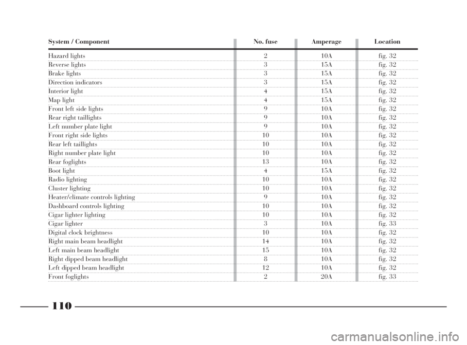
System / Component No. fuse Amperage Location
Hazard lights
Reverse lights
Brake lights
Direction indicators
Interior light
Map light
Front left side lights
Rear right taillights
Left number plate light
Front right side lights
Rear left taillights
Right number plate light
Rear foglights
Boot light
Radio lighting
Cluster lighting
Heater/climate controls lighting
Dashboard controls lighting
Cigar lighter lighting
Cigar lighter
Digital clock brightness
Right main beam headlight
Left main beam headlight
Right dipped beam headlight
Left dipped beam headlight
Front foglights
2 10A fig. 32
3 15A fig. 32
3 15A fig. 32
3 15A fig. 32
4 15A fig. 32
4 15A fig. 32
9 10A fig. 32
9 10A fig. 32
9 10A fig. 32
10 10A fig. 32
10 10A fig. 32
10 10A fig. 32
13 10A fig. 32
4 15A fig. 32
10 10A fig. 32
10 10A fig. 32
9 10A fig. 32
10 10A fig. 32
10 10A fig. 32
3 10A fig. 33
10 10A fig. 32
14 10A fig. 32
15 10A fig. 32
8 10A fig. 32
12 10A fig. 32
2 20A fig. 33
4C090-119 ING 13-03-2008 12:51 Pagina 110