fog light Lancia Ypsilon 2002 Owner handbook (in English)
[x] Cancel search | Manufacturer: LANCIA, Model Year: 2002, Model line: Ypsilon, Model: Lancia Ypsilon 2002Pages: 191, PDF Size: 2.45 MB
Page 47 of 191
44
G
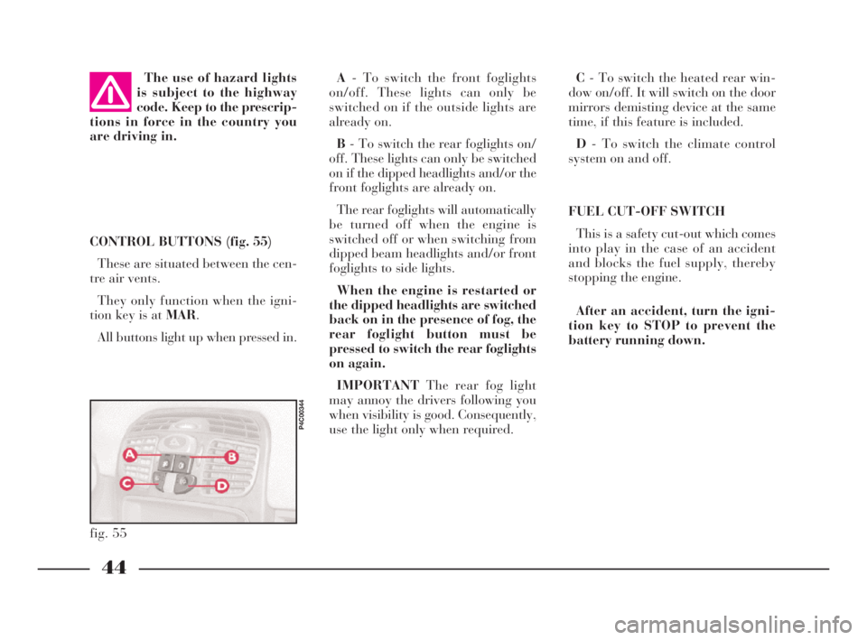
C- To switch the heated rear win-
dow on/off. It will switch on the door
mirrors demisting device at the same
time, if this feature is included.
D- To switch the climate control
system on and off.
FUEL CUT-OFF SWITCH
This is a safety cut-out which comes
into play in the case of an accident
and blocks the fuel supply, thereby
stopping the engine.
After an accident, turn the igni-
tion key to STOP to prevent the
battery running down. CONTROL BUTTONS (fig. 55)
These are situated between the cen-
tre air vents.
They only function when the igni-
tion key is at MAR.
All buttons light up when pressed in. The use of hazard lights
is subject to the highway
code. Keep to the prescrip-
tions in force in the country you
are driving in.
fig. 55
P4C00344
A- To switch the front foglights
on/off. These lights can only be
switched on if the outside lights are
already on.
B- To switch the rear foglights on/
off. These lights can only be switched
on if the dipped headlights and/or the
front foglights are already on.
The rear foglights will automatically
be turned off when the engine is
switched off or when switching from
dipped beam headlights and/or front
foglights to side lights.
When the engine is restarted or
the dipped headlights are switched
back on in the presence of fog, the
rear foglight button must be
pressed to switch the rear foglights
on again.
IMPORTANTThe rear fog light
may annoy the drivers following you
when visibility is good. Consequently,
use the light only when required.
4C001-067 ING 11-03-2008 11:57 Pagina 44
Page 59 of 191

56
G
ABS
The car is fitted with an ABS brak-
ing system that prevents the wheels
locking when braking, it exploits the
grip on the road surface holding the
car in the case of sudden braking.
The driver becomes aware of the
ABS activation through a slight throb-
bing of the brake pedal and the rele-
vant noise it makes.
This does not indicate brake mal-
functioning, it is an indication to the
driver that the ABS is operating. It is
a warning that the car is travelling at
borderline road grip and therefore the
speed should be adjusted to the type
of road surface.
The ABS is an addition to the basic
braking system; in the case of a fail-
ure it disables, leaving the braking
system in the same conditions as a ve-
hicle without ABS installed. COMPENSATION
FOR THE UPWARD SLANT
OF THE HEADLIGHT BEAMS
When the car is loaded, it “slopes”
backwards. This means that the head-
light beam rises. In this case it is nec-
essary to return it to the correct posi-
tion.
The car is fitted with an electric ad-
juster(fig. 84)situated at the side of
the handbrake:
Position0- one or two people on the
front seats.
Position1- five people.
Position2- five people + load in
luggage compartment.
Position3- driver + maximum per-
missible load all in the boot.
fig. 84
P4C00105
Check the positioning of
the headlight beams every
time you change the load
to be carried.
IMPORTANTIn order that the ad-
juster operates properly, the load in
the boot must not exceed the maxi-
mum values indicated.
ADJUSTING THE BEAM
OF THE FRONT FOGLIGHTS
Ask a LANCIA Dealershipto check
and, if necessary, adjust the beam for
you.
4C001-067 ING 11-03-2008 11:57 Pagina 56
Page 77 of 191
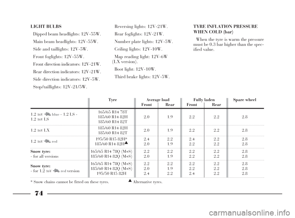
LIGHT BULBS
Dipped beam headlights: 12V-55W.
Main beam headlights: 12V-55W.
Side and taillights: 12V-5W.
Front foglights: 12V-55W.
Front direction indicators: 12V-21W.
Rear direction indicators: 12V-21W.
Side direction indicators: 12V-5W.
Stop/taillights: 12V-21/5W.Reversing lights: 12V-21W.
Rear foglights: 12V-21W.
Number plate lights: 12V-5W.
Ceiling lights: 12V-10W.
Map reading light: 12V-6W
(LX version).
Boot light: 12V-10W.
Third brake lights: 12V-5W.TYRE INFLATION PRESSURE
WHEN COLD (bar)
When the tyre is warm the pressure
must be 0.3 bar higher than the spec-
ified value.
74
G
TyreAverage loadFully laden Spare wheel
Front Rear Front Rear
1.2
16VM Nblue- 1.2 LS - 165/65 R14 78T
1.2
16VLS185/60 R14 82H 2.0 1.9 2.2 2.2 2.8185/60 R14 82T
1.2
16VLX185/60 R14 82H
2.0 1.9 2.2 2.2 2.8185/60 R14 82T
1.2
16VM Nred195/50 R15 82H* 2.4 2.2 2.4 2.2 2.8
185/60 R14 82H▲
2.0 1.9 2.2 2.2 2.8
Snow tyre:165/65 R14 78Q (M+S) 2.2 2.2 2.2 2.2 2.8
- for all versions 185/60 R14 82Q (M+S) 2.0 1.9 2.2 2.2 2.8
Snow tyre:165/65 R14 78Q (M+S) 2.2 2.2 2.2 2.2 2.8
- for 1.2
16VM Nredversion185/60 R14 82Q (M+S) 2.0 1.9 2.2 2.2 2.8195/50 R15 82H 2.4 2.2 2.4 2.2 2.8
* Snow chains cannot be fitted on these tyres.▲
Alternative tyres.
4C068-089 ING 11-03-2008 11:59 Pagina 74
Page 81 of 191
78
G
Here is some advice for driving in
the rain:
– Reduce speed and maintain a
greater safety distance from the cars
in front.
– If it is raining particularly heavily,
visibility is also reduced. In these
cases, switch on the dipped headlights
even if it is still daylight so you can be
seen more easily.
– Do not drive through puddles at
speed and hold on tightly to the
wheel: a puddle taken at high speed
might cause you to lose control of the
car (“aquaplaning”).
– Move the ventilation controls to
the position for demisting the win-
dows (see the section “Getting to
know your car”), to avoid visibility
problems.
– Periodically check the condition of
the windscreen wiper blades.DRIVING IN FOG
– If the fog is thick, do not start out
on a journey unless you absolutely
have to.
If driving in mist, blanket fog or
when there is the danger of fog
patches:
– Keep your speed down.
– Turn on the dipped headlights,
rear foglights and front foglights, if
fitted, even during the day. Do not
drive with your headlights at full-
beam.
– Remember that fog also means the
tarmac is wet and therefore manoeu-
vres of all kinds are more difficult and
stopping distances are longer.
– Keep a good distance from the cars
in front of you.
– As far as possible, avoid spurts of
speed or sudden deceleration.
– Do not overtake other vehicles if
you can help it.– If you are forced to stop your car
(breakdown, limited visibility etc.)
try to stop off the road. Turn on the
hazard lights and, if possible, the
dipped headlights. Rhythmically
sound the horn if you realise another
car is coming.
IMPORTANTOn stretches of road
with good visibility, switch off your
rear foglights; the brightness of these
lights could annoy the people travel-
ling in the cars behind.
4C068-089 ING 11-03-2008 11:59 Pagina 78
Page 104 of 191

101
fG
C Tubular bulbs
Release these bulbs from rela-
tive contacts to remove them.
D Halogen bulbs
Release the securing spring
from its seat to remove the
bulb.BULB Fig. 9 TYPE POWER
Main beam headlights
Dipped beam headlights
Front side lights
Front direction indicators
Side direction indicators
Rear direction indicators
Foglights
Reverse lights
Rear brake and side lights
Rear side lights
Rear fog lights
Third brake light
Number plate
Ceiling light (1.2 16VM Nblue- LS versions)
Ceiling light:
– with courtesy light
– with map light
BootD H3 12V-55W
D H7 12V-55W
A W5W 12V-5W
B PY21W 12V-21W
A W5W 12V-5W
B PY21W 12V-21W
D H1 12V-55W
B P21W 12V-21W
B R5W 12V-21/5W
B R5W 12V-21W
B P21W 12V-21W
A W5W 12V-5W
C C5W 12V-5W
C – 12V-10W
C – 12V-10W
A – 12V-6W
C C5W 12V-5W
4C090-119 ING 13-03-2008 12:51 Pagina 101
Page 107 of 191

REAR LIGHT CLUSTER
1)From inside the car boot, lift the
carpeting and undo screw A (fig. 19)
securing the light cluster.
2)Remove the light cluster B.
3)Replace the burnt-out bulb by
pushing it slightly and turning anti-
clockwise.
Bulbs in (fig. 20):
C - 12V-21W (orange) (type PY21W)
for the direction indicators.
D - 12-21W (type P21W) for the re-
versing lights.
104
fG
3)Remove the bulb holder B
(fig. 16)fromCin the lens.
4)Remove press-fit bulb Dand re-
place it.
5)Refit the bulb holder into Cand
then fit the lens.
FRONT FOGLIGHTS
To replace the halogen bulb 12V-
55W (type H1):
1)Turn the wheels to the right to get
at the left light, and to the left to get
at the right light.
2)Unscrew screw A (fig. 17)in the
cover on the wheelarch.3)Turn cover Bin an anticlockwise
direction.
4)Release clip D (fig. 18)and re-
move bulbC.
5)Release the clip Dand screw
coverBback in.
fig. 16
P4C00383
fig. 17
P4C00152
fig. 18
P4C00406
fig. 19
P4C00038
4C090-119 ING 13-03-2008 12:51 Pagina 104
Page 108 of 191

105
fG
E- 12V-21/5W (type R5W) for the
brake and taillights.
F- 12V-5W (type R5W) for the tail-
lights.
G- 12V-21W (type P21W) for the
rear foglights.
5)Refit the lighting cluster, and
tighten screw A (fig. 19), without
forcing it.THIRD BRAKE LIGHT
To change one or more 12V-5W
(type W5W) bulbs:
1)Unscrew the two screws A (fig. 21)
and remove trim B.
2)Loosen the two screws C (fig. 22),
disconnect the connector Dand sep-
arate the lens from the cover B.
3)Loosen the tab E (fig. 23)and
separate the bulbs from the lens.4)Replace the burnt-out bulb F
(fig. 23).
5)Refit the unit by reversing the
various operations.
fig. 20
P4C00039
fig. 21
P4C00407
fig. 22
P4C00408
fig. 23
P4C00409
4C090-119 ING 13-03-2008 12:51 Pagina 105
Page 113 of 191
110
fG
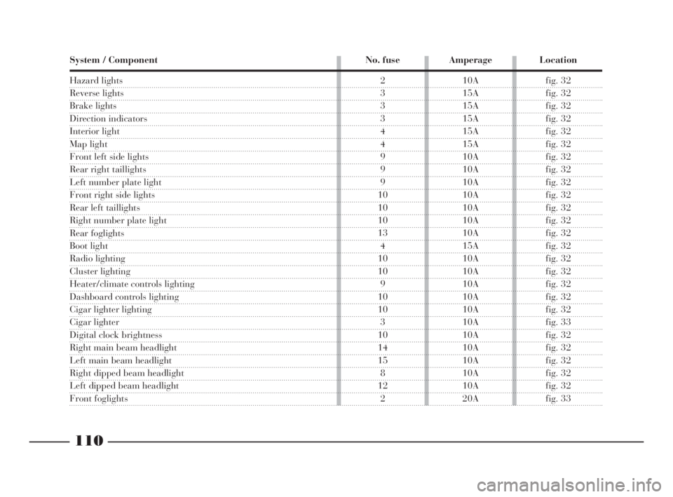
System / Component No. fuse Amperage Location
Hazard lights
Reverse lights
Brake lights
Direction indicators
Interior light
Map light
Front left side lights
Rear right taillights
Left number plate light
Front right side lights
Rear left taillights
Right number plate light
Rear foglights
Boot light
Radio lighting
Cluster lighting
Heater/climate controls lighting
Dashboard controls lighting
Cigar lighter lighting
Cigar lighter
Digital clock brightness
Right main beam headlight
Left main beam headlight
Right dipped beam headlight
Left dipped beam headlight
Front foglights
2 10A fig. 32
3 15A fig. 32
3 15A fig. 32
3 15A fig. 32
4 15A fig. 32
4 15A fig. 32
9 10A fig. 32
9 10A fig. 32
9 10A fig. 32
10 10A fig. 32
10 10A fig. 32
10 10A fig. 32
13 10A fig. 32
4 15A fig. 32
10 10A fig. 32
10 10A fig. 32
9 10A fig. 32
10 10A fig. 32
10 10A fig. 32
3 10A fig. 33
10 10A fig. 32
14 10A fig. 32
15 10A fig. 32
8 10A fig. 32
12 10A fig. 32
2 20A fig. 33
4C090-119 ING 13-03-2008 12:51 Pagina 110
Page 176 of 191

173
G
For mechanical connections, the fol-
lowing must be used:
– “CUNA 501” 1
stclass ball coupling
(CUNA NC 138-40 table);
– “CUNA 501” 1
stclass socket cou-
pling (CUNA NC 438-40 table).For the electric connection a 7-pole,
12 Volt coupling must be used
(CUNA UNI 9128).
The electric coupling must be fixed
on a special mount to be attached to
the ball coupling.
The electrical functions for the cou-
pling must be connected as illustrated
in(fig. 5).
In addition to the electrical connec-
tions (illustrated in the diagram that
follows), only the lead for powering
an electric brake and the lead to
power a light inside the trailer not ex-
ceeding 15W may be connected to the
car’s electrical system.
The electric brake must be powered
directly from the battery by means of
a lead with a cross-section no less
than 2.5 sq. mm.
Location of the components
on the car:
1.Left taillight (rear foglight con-
nection) - 2.Right taillight (brake
lights connection) - 3.Pole socket -
4.Trailer direction indicators power
supply relays - 5.High-amp fusebox
-6.Branching box. TOW HITCH INSTALLATION
(fig. 5)
The tow hitch must be fixed to the
body by an expert in accordance with
the following instructions and with
any additional instructions or infor-
mation provided by the tow hitch
manufacturer.
fig. 5
P4C00416
4C168-176 ING 11-03-2008 12:03 Pagina 173
Page 181 of 191
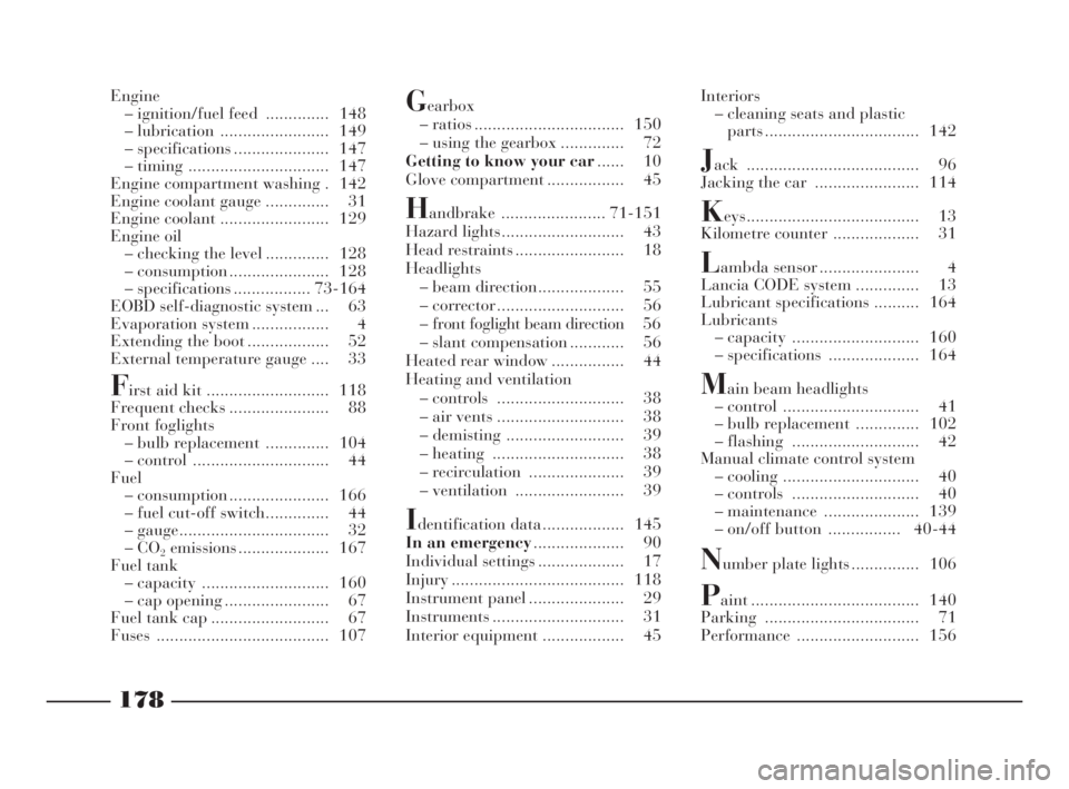
178
fdG
Interiors
– cleaning seats and plastic
parts .................................. 142
Jack ...................................... 96
Jacking the car ....................... 114
Keys...................................... 13
Kilometre counter ................... 31
Lambda sensor ...................... 4
Lancia CODE system .............. 13
Lubricant specifications .......... 164
Lubricants
– capacity ............................ 160
– specifications .................... 164
Main beam headlights
– control .............................. 41
– bulb replacement .............. 102
– flashing ............................ 42
Manual climate control system
– cooling .............................. 40
– controls ............................ 40
– maintenance ..................... 139
– on/off button ................ 40-44
Number plate lights ............... 106
Paint ..................................... 140
Parking .................................. 71
Performance ........................... 156 Engine
– ignition/fuel feed .............. 148
– lubrication ........................ 149
– specifications ..................... 147
– timing ............................... 147
Engine compartment washing . 142
Engine coolant gauge .............. 31
Engine coolant ........................ 129
Engine oil
– checking the level .............. 128
– consumption ...................... 128
– specifications ................. 73-164
EOBD self-diagnostic system ... 63
Evaporation system ................. 4
Extending the boot .................. 52
External temperature gauge .... 33
First aid kit ........................... 118
Frequent checks ...................... 88
Front foglights
– bulb replacement .............. 104
– control .............................. 44
Fuel
– consumption ...................... 166
– fuel cut-off switch.............. 44
– gauge................................. 32
–CO
2emissions .................... 167
Fuel tank
– capacity ............................ 160
– cap opening ....................... 67
Fuel tank cap .......................... 67
Fuses ...................................... 107
Gearbox
– ratios ................................. 150
– using the gearbox .............. 72
Getting to know your car...... 10
Glove compartment ................. 45
Handbrake ....................... 71-151
Hazard lights........................... 43
Head restraints ........................ 18
Headlights
– beam direction................... 55
– corrector ............................ 56
– front foglight beam direction 56
– slant compensation ............ 56
Heated rear window ................ 44
Heating and ventilation
– controls ............................ 38
– air vents ............................ 38
– demisting .......................... 39
– heating ............................. 38
– recirculation ..................... 39
– ventilation ........................ 39
Identification data .................. 145
In an emergency.................... 90
Individual settings ................... 17
Injury ...................................... 118
Instrument panel ..................... 29
Instruments ............................. 31
Interior equipment .................. 45
4C177-184 Indice ING 13-03-2008 13:31 Pagina 178