roof Lancia Ypsilon 2002 Owner handbook (in English)
[x] Cancel search | Manufacturer: LANCIA, Model Year: 2002, Model line: Ypsilon, Model: Lancia Ypsilon 2002Pages: 191, PDF Size: 2.45 MB
Page 13 of 191
You are recommended to read this chapter sit-
ting comfortably in your new Lancia Y. In this
way you will be able to identify the parts de-
scribed immediate and see for yourself what you
have just read.
In short, you will increase your knowledge of your
Lancia Y with its controls and other devices. Later,
when you start the engine and join the traffic you
will make a host of other pleasant discoveries.
DASHBOARD................................................. 11
THE LANCIA CODE SYSTEM....................... 13
IGNITION SWITCH ........................................ 16
INDIVIDUAL SETTINGS ............................... 17
SEAT BELTS .................................................. 21
TRANSPORTING CHILDREN SAFELY .......... 26
INSTRUMENT PANEL ................................... 29
INSTRUMENTS............................................. 31
WARNING LIGHTS ........................................ 34HEATING AND VENTILATION ..................... 37
CLIMATE CONTROL SYSTEM....................... 40
STEERING COLUMN STALKS ...................... 41
CONTROLS.................................................... 43
INTERIOR EQUIPMENT ................................ 45
SUNROOF...................................................... 48
DOORS........................................................... 49
BOOT ............................................................. 51
BONNET........................................................ 53
SKI AND ROOF RACKS................................. 55
HEADLIGHTS............................................... 55
ABS ................................................................ 56
FRONT AND SIDE AIRBAGS.......................... 58
EOBD SYSTEM............................................... 63
SOUND SYSTEM ........................................... 64
RADIO-NAVIGATION SYSTEM..................... 65
CELLULAR PHONE SETUP........................... 66
FUEL TANK CAP ............................................ 67
10
G
GETTING TO KNOW YOUR CAR
4C001-067 ING 11-03-2008 11:57 Pagina 10
Page 51 of 191

48
G
A key C (fig. 67)is attached to the
back of the cover B (fig. 67); insert
this key into D (fig. 68) and turn it to
manually perform the operations de-
scribed previously (opening/closing).
To reach D, remove the press-fitted
cover.
fig. 68
P4C00187
Do not open the roof if
there is snow or ice on it as
you risk damaging it.
SUNROOF
The sunroof is electrically operated.
It will only work if the ignition key
is at MAR.
ButtonA (fig. 65)on the ceiling light
unit controls the opening, closing,
raising and lowering of the roof.
When you release the button, the
roof locks in the position it is in at
that moment.
£Press once to open in the spoiler
position.
Press again to open completely.
¢Press to close.
fig. 65
P4C00101
A sliding sunshade, fitted under the
sunroof, will lessen the effect of the
sun’s rays or the amount of air enter-
ing the car (fig. 66).
If there is an electrical fault in the
sunroof, open the glove compartment.
fig. 66
P4C00102
fig. 67
P4C00103
4C001-067 ING 11-03-2008 11:57 Pagina 48
Page 52 of 191

49
G
DOORS
SIDE DOORS CENTRAL
LOCKING/UNLOCKING
Unlocking from the outside
Insert the key into one of the two
doors and turn it to position 2
(fig. 69), then lift the door handle. Only open or close the
sunroof when the car is
stationary.
Incorrect use of the sun-
roof could be dangerous.
Before and when pressing
the switch, always make sure that
passengers are not liable to injury
either directly by the movement of
the sunroof or by personal effects
being dragged along or knocked
by the roof.
Always remove the igni-
tion key when getting out
of the car to make sure
that the sunroof cannot be acci-
dentally operated and constitute a
hazard for passengers remaining
in the car.
fig. 69
P4C00020
Before opening a door,
make sure that the condi-
tions are safe to carry out
the manoeuvre.
Locking from the outside
Turn the key to position 1 (fig. 69).
Opening/locking the doors
from the inside
With the doors closed, press (to
lock) or lift (to unlock) the door open-
ing lever A (fig. 70)on either the dri-
ver’s or the passenger’s side.
A green sector B(covered when the
lock is off) will appear when the door
is locked (lever Adown). The instru-
ment panel warning light
´may light
up if the doors are not closed perfectly
in some versions.
fig. 70
P4C00019
4C001-067 ING 11-03-2008 11:57 Pagina 49
Page 58 of 191
55
G
SKI AND
ROOF RACKS
ANCHORAGE HOOKS
POSITIONING
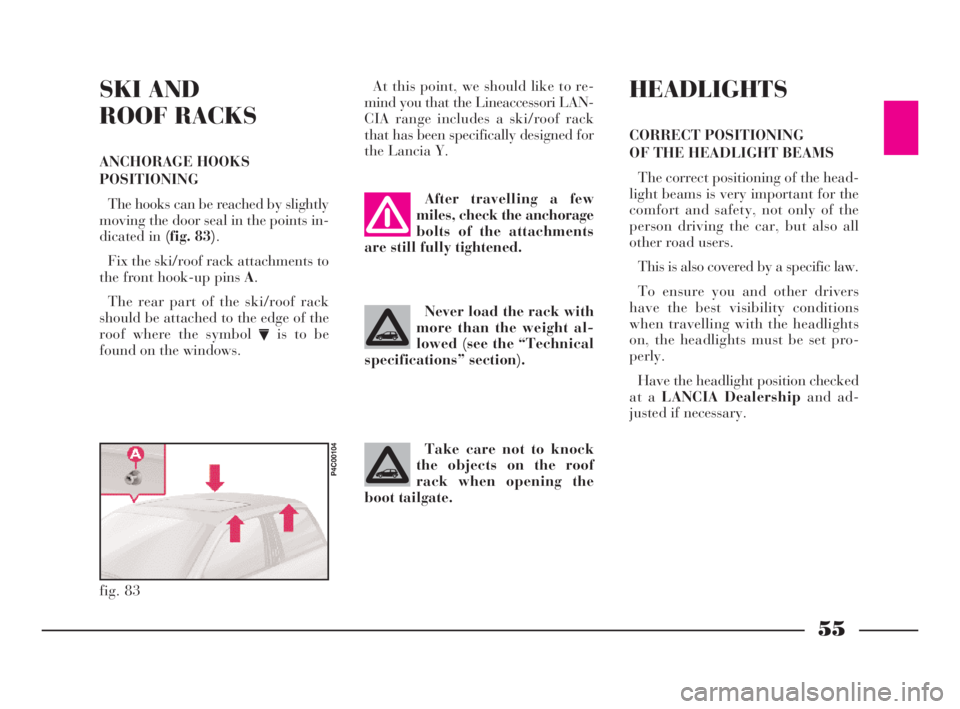
The hooks can be reached by slightly
moving the door seal in the points in-
dicated in (fig. 83).
Fix the ski/roof rack attachments to
the front hook-up pins A.
The rear part of the ski/roof rack
should be attached to the edge of the
roof where the symbol
Vis to be
found on the windows.At this point, we should like to re-
mind you that the Lineaccessori LAN-
CIA range includes a ski/roof rack
that has been specifically designed for
the Lancia Y.
fig. 83
P4C00104
After travelling a few
miles, check the anchorage
bolts of the attachments
are still fully tightened.
Never load the rack with
more than the weight al-
lowed (see the “Technical
specifications” section).
Take care not to knock
the objects on the roof
rack when opening the
boot tailgate.
HEADLIGHTS
CORRECT POSITIONING
OF THE HEADLIGHT BEAMS
The correct positioning of the head-
light beams is very important for the
comfort and safety, not only of the
person driving the car, but also all
other road users.
This is also covered by a specific law.
To ensure you and other drivers
have the best visibility conditions
when travelling with the headlights
on, the headlights must be set pro-
perly.
Have the headlight position checked
at a LANCIA Dealershipand ad-
justed if necessary.
4C001-067 ING 11-03-2008 11:57 Pagina 55
Page 68 of 191

65
G
BASIC SOUND SYSTEM -
optional
This consists of the following:
– 2 front tweeter speakers;
– 2 full-range speakers in the doors;
– rear speaker cables;
– wire and manual radio aerial lo-
cated on the front of the roof.
For electrical connec-
tions, see the section “Ac-
cessory installation”.SOUND SYSTEM
The complete system consists of the
following:
– basic system (see previous para-
graph).
– Clarion PU2312 sound system
with CD player (fig. 92)(for charac-
teristics and instructions see attached
supplement).
– case for front panel.
– brackets for removing radio unit.
– 2 rear speakers;
– CD CHANGER (where fitted) wire
with respecting connector located on
right-hand side of the boot, where you
can install a compatible CD
CHANGER if required.
fig. 91
P4C00110
fig. 92
P4C00380
RADIO-NAVIGATION
SYSTEM
The complete system consists of the
following:
– basic system (see previous para-
graph).
– Blaupunkt radio-navigator (fig. 93)
(for characteristics and instructions see
attached supplement).
– brackets for removing radio-navi-
gator unit.
– 2 rear speakers.
– CD CHANGER wire with respect-
ing connector located on right-hand
side of the boot, where you can install
a compatible CD CHANGER if re-
quired.
fig. 93
P4C00422
4C001-067 ING 11-03-2008 11:57 Pagina 65
Page 69 of 191
66
G
CELLULAR PHONE
SETUP
If the car has been ordered to in-
clude provision for the fitting of cel-
lular phones, it will have:
– one dual purpose speaker (sound
system and cellular phone) located in
the right-hand door;
– one dual purpose aerial (sound
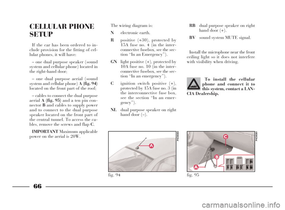
system and cellular phone) A (fig. 94)
located on the front part of the roof;
– cables to connect the dual purpose
aerialA (fig. 95)and a ten pin con-
nectorBand cables to supply power
and to connect to the dual purpose
speaker located on the front part of
the central tunnel. To access the ca-
bles, remove the screws and flap C.
IMPORTANTMaximum applicable
power on the aerial is 20W.The wiring diagram is:
Nelectronic earth.
Rpositive (+30), protected by
15A fuse no. 4 (in the inter-
connective fusebox, see the sec-
tion “In an Emergency”).
GNlight positive (+), protected by
10A fuse no. 10 (in the inter-
connective fusebox, see the sec-
tion “In an emergency”).
Cignition switch positive (+),
protected by 15A fuse no. 3 (in
the interconnective fuse box,
see the section “In an emer-
gency”).
NLdual purpose speaker on right
hand door (–).To install the cellular
phone and connect it to
this system, contact a LAN-
CIA Dealership.
fig. 94
P4C00303
RBdual purpose speaker on right
hand door (+).
BVsound system MUTE signal.
Install the microphone near the front
ceiling light so it does not interfere
with visibility when driving.
fig. 95
P4C00361
4C001-067 ING 11-03-2008 11:57 Pagina 66
Page 84 of 191
81
G
CONTAINING
RUNNING COSTS
AND POLLUTION
Some suggestions which may help
you to keep the running costs of your
car down and lower the amount of
toxic emissions released into the at-
mosphere are given below.
GENERAL CONSIDERATIONS
Car maintenance
The overall state of the car is an im-
portant factor which has a marked in-
fluence over fuel consumption and
driving comfort and on the life span
of your car. For this reason care
should be taken to maintain your ve-
hicle by carrying out the necessary
checks and regulations in accordance
with the specifications given in the
Servize Schedule (see spark plugs,
idle, air filters, timing sections).Tyres
Tyres should be checked at least
every four weeks: if the pressure is too
low fuel consumption increases as the
resistance to the rolling movement of
the tyre is greater. In this state, tyre
wear is increased and car handling
suffers which will affect safety.
Unnecessary loads
Do not travel with too much luggage
stowed in the boot. The weight of the
car (especially when driving in town)
and its trim greatly affects consump-
tion and stability.
Roof/ski racks
Remove roof or ski racks from the
roof of the car as soon as they are no
longer needed. These accessories re-
duce the aerodynamic penetration of
the car and will increase consump-
tion. When transporting particularly
large objects, use a trailer where pos-
sible.Electrical devices
Use the electrical devices for the nec-
essary time only. The heated rear win-
dow, supplementary lights, wind-
screen wipers, heating system blower
require large amounts of energy and,
increasing the request for power also
increases fuel consumption (up to
+25% when driving in built-up areas).
Air conditioner
The air conditioner is an additional
load which greatly affects the engine
leading to higher consumption (on av-
erage up to +20%). When the tem-
perature outside the car permits it,
use the air vents where possible.
Spoilers
The use of aerodynamic optional ex-
tras which are not certified for specific
use on the car, may reduce the aero-
dynamic penetration of the car and
increase consumption.
4C068-089 ING 11-03-2008 11:59 Pagina 81
Page 115 of 191
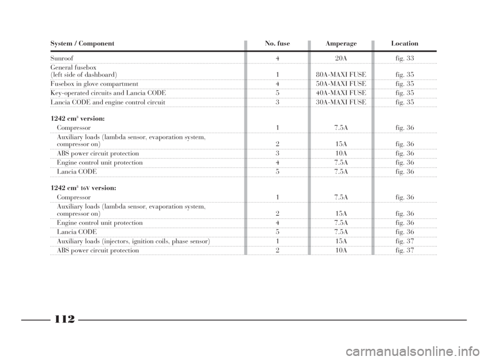
112
fG
System / Component No. fuse Amperage Location
Sunroof
General fusebox
(left side of dashboard)
Fusebox in glove compartment
Key-operated circuits and Lancia CODE
Lancia CODE and engine control circuit
1242 cm
3version:
Compressor
Auxiliary loads (lambda sensor, evaporation system,
compressor on)
ABS power circuit protection
Engine control unit protection
Lancia CODE
1242 cm
316Vversion:
Compressor
Auxiliary loads (lambda sensor, evaporation system,
compressor on)
Engine control unit protection
Lancia CODE
Auxiliary loads (injectors, ignition coils, phase sensor)
ABS power circuit protection4 20A fig. 33
1 80A-MAXI FUSE fig. 35
4 50A-MAXI FUSE fig. 35
5 40A-MAXI FUSE fig. 35
3 30A-MAXI FUSE fig. 35
1 7.5A fig. 36
2 15A fig. 36
3 10A fig. 36
4 7.5A fig. 36
5 7.5A fig. 36
1 7.5A fig. 36
2 15A fig. 36
4 7.5A fig. 36
5 7.5A fig. 36
1 15A fig. 37
2 10A fig. 37
les
00
ed
az-
ve
4C090-119 ING 13-03-2008 12:51 Pagina 112
Page 144 of 191

141
G
IMPORTANTCars with optional
“Kaleidos” options (non-standard
personalised paint colours), can be re-
paired in exactly the same way as
other cars painted with standard
colours at your LANCIA Dealership.To wash the car properly:
1)Remove the aerial from the roof
to prevent damaging it when washing
the car in an automatic carwash.
2)Wet the body using a low pressure
jet of water.
3)Wipe a sponge with a slightly
soapy solution over the bodywork,
frequently rinsing the sponge.
4)Rinse well with water and dry
with a jet of air or a chamois leather.
When drying the car, be careful to
get at those parts which are not so
easily seen e.g. the door frames, bon-
net and around the headlights where
water can most readily collect. You
are advised not to take the car into a
closed area immediately, but to leave
it out in the open so any water left can
evaporate more easily.
Do not wash the car after it has been
parked in the sun or while the bonnet
is hot: it could take the shine off the
paint.
External plastic parts must be
cleaned following the usual car wash-
ing procedure. As far as possible avoid parking your
car under trees; the resinous sub-
stances which often drop from certain
types of trees could dull the paint and
increase the possibility of rusting.
IMPORTANTBird droppings must
be washed off immediately and with
great care as their acid is particularly
aggressive.
Detergents pollute water.
For this reason, the car
must be washed in an area
equipped for the collection and
purification of the liquids used
while washing.
IMPORTANTWashing is to be car-
ried out with the engine cold and the
ignition key on STOP. After washing
make sure that the various protections
(rubber sheaths and other guards)
have not moved from their positions
or been damaged.
4C120-143 ING 11-03-2008 12:01 Pagina 141
Page 160 of 191
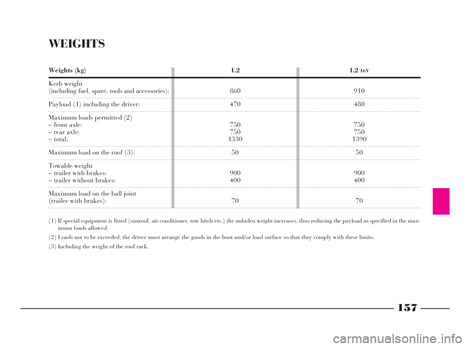
157
G
WEIGHTS
Weights (kg)
Kerb weight
(including fuel, spare, tools and accessories):
Payload (1) including the driver:
Maximum loads permitted (2)
– front axle:
– rear axle:
– total:
Maximum load on the roof (3):
Towable weight
– trailer with brakes:
– trailer without brakes:
Maximum load on the ball joint
(trailer with brakes):1.2
16V
910
480
750
750
1390
50
900
400
70 1.2
860
470
750
750
1330
50
900
400
70
(1) If special equipment is fitted (sunroof, air conditioner, tow hitch etc.) the unladen weight increases, thus reducing the payload as specified in the max-
imum loads allowed.
(2) Loads not to be exceeded: the driver must arrange the goods in the boot and/or load surface so that they comply with these limits.
(3) Including the weight of the roof rack.
4C144-167 ING 11-03-2008 12:02 Pagina 157