fuel type Lancia Ypsilon 2002 Owner handbook (in English)
[x] Cancel search | Manufacturer: LANCIA, Model Year: 2002, Model line: Ypsilon, Model: Lancia Ypsilon 2002Pages: 191, PDF Size: 2.45 MB
Page 16 of 191

13
G
THE LANCIA
CODE SYSTEM
To further protect your car from at-
tempted theft, it has been fitted with
an electronic engine immobiliser sys-
tem called “Lancia CODE”, which is
currently considered the most effec-
tive way of protecting your car against
theft.This system is automatically
activated each time the engine is
switched off. Each ignition key, in
fact, contains an electronic device
which modulates a radio-frequency
signal emitted by a special aerial dur-
ing ignition. The modulated signal is
a “password” with which the control
unit recognises the key. Engine igni-
tion is enabled only if the key is recog-
nised by the system.THE KEYS
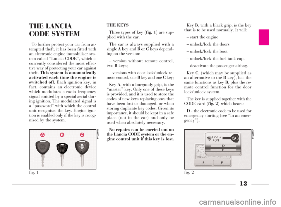
Three types of key (fig. 1) are sup-
plied with the car.
The car is always supplied with a
singleAkey and BorCkeys depend-
ing on the version:
– version without remote control,
twoBkeys;
– versions with door lock/unlock re-
mote control, one Bkey and one Ckey;
KeyA, with a burgundy grip, is the
“master” key. Only one of these keys
is provided, and it is used to store the
codes of new keys replacing ones that
have been lost or damaged, or when
storing duplicate key codes. Given its
importance, it should be kept in a safe
place (not in the car) and only be
used when absolutely necessary.
No repairs can be carried out on
the Lancia CODE system or the en-
gine control unit if this key is lost.KeyB, with a black grip, is the key
that is to be used normally. It will:
– start the engine
– unlock/lock the doors
– unlock/lock the boot
– unlock/lock the fuel tank cap.
– deactivate the passenger airbag.
KeyC, (which may be supplied as
an alternative to the Bkey), has the
same functions as key B, plus the re-
mote control function for the door
lock/unlock system.
The key is supplied together with the
CODE card (fig. 2) which bears:
D- the electronic code to be used for
emergency starting (see “In an emer-
gency”);
fig. 1
P4C00056
fig. 2
P4C00057
4C001-067 ING 11-03-2008 11:57 Pagina 13
Page 70 of 191

67
G
Only change the fuel filler cap with
a genuine spare part in order not to
compromise the petrol fume recovery
system.FUEL TANK CAP
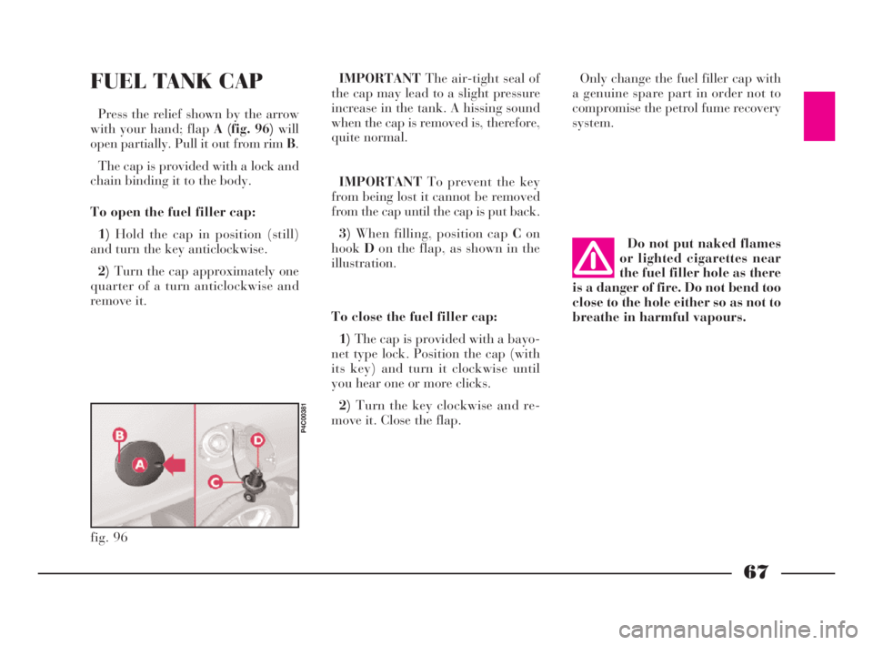
Press the relief shown by the arrow
with your hand; flapA (fig. 96)will
open partially. Pull it out from rim B.
The cap is provided with a lock and
chain binding it to the body.
To open the fuel filler cap:
1)Hold the cap in position (still)
and turn the key anticlockwise.
2)Turn the cap approximately one
quarter of a turn anticlockwise and
remove it.IMPORTANTThe air-tight seal of
the cap may lead to a slight pressure
increase in the tank. A hissing sound
when the cap is removed is, therefore,
quite normal.
IMPORTANTTo prevent the key
from being lost it cannot be removed
from the cap until the cap is put back.
3)When filling, position cap Con
hookDon the flap, as shown in the
illustration.
To close the fuel filler cap:
1)The cap is provided with a bayo-
net type lock. Position the cap (with
its key) and turn it clockwise until
you hear one or more clicks.
2)Turn the key clockwise and re-
move it. Close the flap.Do not put naked flames
or lighted cigarettes near
the fuel filler hole as there
is a danger of fire. Do not bend too
close to the hole either so as not to
breathe in harmful vapours.
fig. 96
P4C00381
4C001-067 ING 11-03-2008 11:57 Pagina 67
Page 151 of 191

148
G
FUEL SUPPLY / IGNITION
1.2 versions
Integrated electronic injection and
ignition system: a single electronic
control unit controls both functions.
It processes both the time the injec-
tion lasts (for fuel metering) and the
spark advance angle.
– Type: ......................Multi-point.
– Method of measuring the amount
of aspirated air for petrol metering:
“Speed density” (*).
– “Closed loop”: information on
combustion for correct petrol meter-
ing achieved by means of two lambda
sensors (one upstream and the other
downstream with respect to the catal-
yser).– Electric petrol pump: in-tank.
– Injection pressure: ......... 3.5 bar.
– Air cleaner: dry-type with paper
filter element.
– Firing order: ................1-3-4-2.
– Engine idling speed: 750±50 rpm.
– Spark plugs:
Champion.................RC10YCC
NGK ........................... BKR5EZ1.216Vversions
Integrated electronic injection and
ignition system: a single electronic
control unit controls both functions.
It processes both the time the injec-
tion lasts (for fuel metering) and the
spark advance angle.
– Type: ......................Multi-point.
– Method of measuring the amount
of aspirated air for “Speed density”
petrol metering (*).
– “Closed loop”: information on
combustion for correct petrol meter-
ing achieved by means of two lambda
sensors (one upstream and the other
downstream with respect to the catal-
yser).
– Electric petrol pump: in-tank.
4C144-167 ING 11-03-2008 12:02 Pagina 148
Page 152 of 191

149
G
– Injection pressure: ......... 3.5 bar.
– Air cleaner: dry-type with paper
filter element.
– Firing order: ................1-3-4-2.
– Engine idling speed: 700±50 rpm.
– Spark plugs:
NGK ..........................DCPR8E-N
(*) Analytic method, by electronically process-
ing data from the engine rpm (speed) sensor
and from the air temperature and absolute pres-
sure sensors in the intake manifold (density).
LUBRICATION
Forced-fed with gear pump with
pressure relief valve incorporated.
Oil purification through full-flow
cartridge filter.
COOLING
Cooling system with radiator, cen-
trifugal pump and expansion tank.
“Fixed by-pass” thermostat(1.2 en-
gine)” on the secondary circuit for the
recirculation of water from the engine
to the radiator.
Electric fan for radiator cooling on
the radiator with switching on/off
controlled by thermostatic switch lo-
cated on the radiator. Modifications or repairs
to the fuel feed system that
are not carried out prop-
erly or do not take the system’s
technical specifications into ac-
count can cause malfunctions with
the risk of fire.
4C144-167 ING 11-03-2008 12:02 Pagina 149