radio Lancia Ypsilon 2002 Owner handbook (in English)
[x] Cancel search | Manufacturer: LANCIA, Model Year: 2002, Model line: Ypsilon, Model: Lancia Ypsilon 2002Pages: 191, PDF Size: 2.45 MB
Page 13 of 191
You are recommended to read this chapter sit-
ting comfortably in your new Lancia Y. In this
way you will be able to identify the parts de-
scribed immediate and see for yourself what you
have just read.
In short, you will increase your knowledge of your
Lancia Y with its controls and other devices. Later,
when you start the engine and join the traffic you
will make a host of other pleasant discoveries.
DASHBOARD................................................. 11
THE LANCIA CODE SYSTEM....................... 13
IGNITION SWITCH ........................................ 16
INDIVIDUAL SETTINGS ............................... 17
SEAT BELTS .................................................. 21
TRANSPORTING CHILDREN SAFELY .......... 26
INSTRUMENT PANEL ................................... 29
INSTRUMENTS............................................. 31
WARNING LIGHTS ........................................ 34HEATING AND VENTILATION ..................... 37
CLIMATE CONTROL SYSTEM....................... 40
STEERING COLUMN STALKS ...................... 41
CONTROLS.................................................... 43
INTERIOR EQUIPMENT ................................ 45
SUNROOF...................................................... 48
DOORS........................................................... 49
BOOT ............................................................. 51
BONNET........................................................ 53
SKI AND ROOF RACKS................................. 55
HEADLIGHTS............................................... 55
ABS ................................................................ 56
FRONT AND SIDE AIRBAGS.......................... 58
EOBD SYSTEM............................................... 63
SOUND SYSTEM ........................................... 64
RADIO-NAVIGATION SYSTEM..................... 65
CELLULAR PHONE SETUP........................... 66
FUEL TANK CAP ............................................ 67
10
G
GETTING TO KNOW YOUR CAR
4C001-067 ING 11-03-2008 11:57 Pagina 10
Page 14 of 191
11
G
DASHBOARD
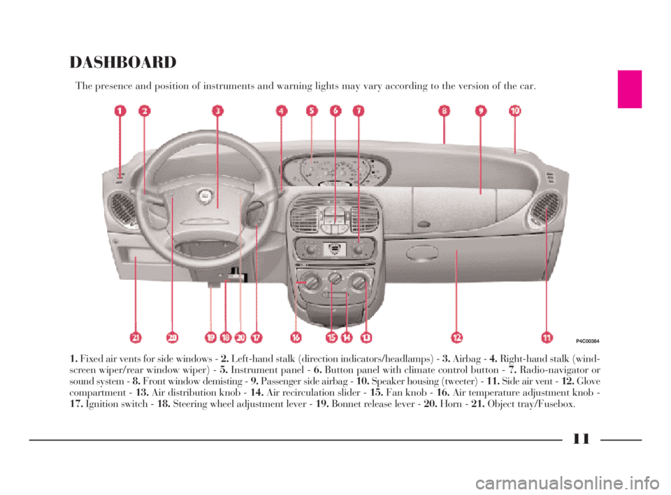
The presence and position of instruments and warning lights may vary according to the version of the car.
1.Fixed air vents for side windows - 2.Left-hand stalk (direction indicators/headlamps) - 3.Airbag - 4.Right-hand stalk (wind-
screen wiper/rear window wiper) - 5.Instrument panel - 6.Button panel with climate control button - 7.Radio-navigator or
sound system - 8.Front window demisting - 9.Passenger side airbag - 10.Speaker housing (tweeter) - 11.Side air vent - 12.Glove
compartment - 13.Air distribution knob - 14.Air recirculation slider - 15.Fan knob - 16.Air temperature adjustment knob -
17.Ignition switch - 18.Steering wheel adjustment lever - 19.Bonnet release lever - 20.Horn - 21.Object tray/Fusebox.
P4C00364
4C001-067 ING 11-03-2008 11:57 Pagina 11
Page 16 of 191
13
G
THE LANCIA
CODE SYSTEM
To further protect your car from at-
tempted theft, it has been fitted with
an electronic engine immobiliser sys-
tem called “Lancia CODE”, which is
currently considered the most effec-
tive way of protecting your car against
theft.This system is automatically
activated each time the engine is
switched off. Each ignition key, in
fact, contains an electronic device
which modulates a radio-frequency
signal emitted by a special aerial dur-
ing ignition. The modulated signal is
a “password” with which the control
unit recognises the key. Engine igni-
tion is enabled only if the key is recog-
nised by the system.THE KEYS
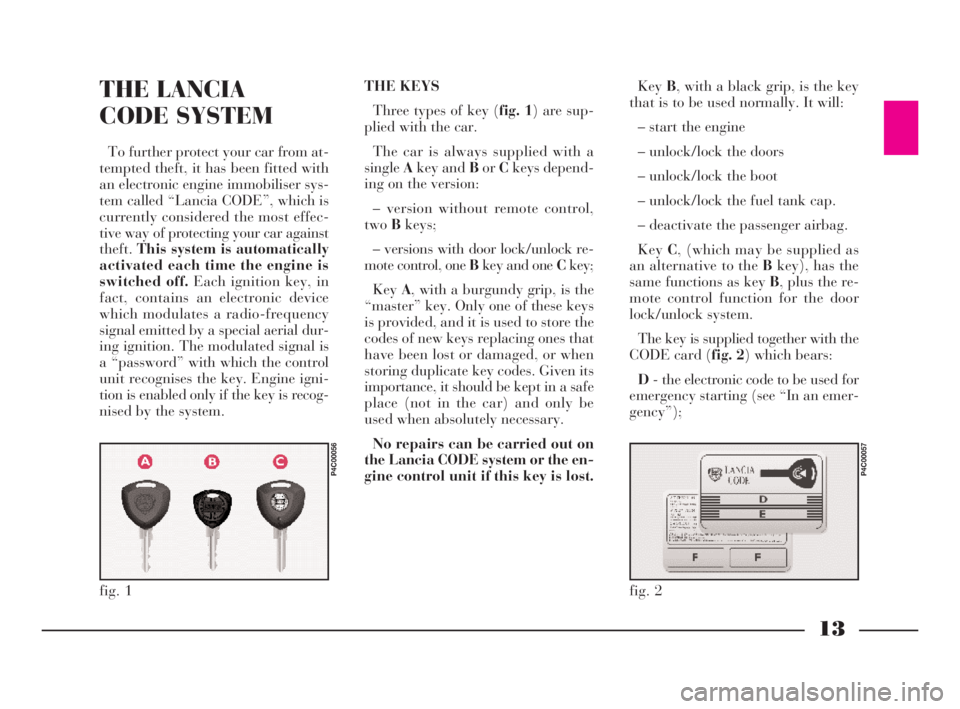
Three types of key (fig. 1) are sup-
plied with the car.
The car is always supplied with a
singleAkey and BorCkeys depend-
ing on the version:
– version without remote control,
twoBkeys;
– versions with door lock/unlock re-
mote control, one Bkey and one Ckey;
KeyA, with a burgundy grip, is the
“master” key. Only one of these keys
is provided, and it is used to store the
codes of new keys replacing ones that
have been lost or damaged, or when
storing duplicate key codes. Given its
importance, it should be kept in a safe
place (not in the car) and only be
used when absolutely necessary.
No repairs can be carried out on
the Lancia CODE system or the en-
gine control unit if this key is lost.KeyB, with a black grip, is the key
that is to be used normally. It will:
– start the engine
– unlock/lock the doors
– unlock/lock the boot
– unlock/lock the fuel tank cap.
– deactivate the passenger airbag.
KeyC, (which may be supplied as
an alternative to the Bkey), has the
same functions as key B, plus the re-
mote control function for the door
lock/unlock system.
The key is supplied together with the
CODE card (fig. 2) which bears:
D- the electronic code to be used for
emergency starting (see “In an emer-
gency”);
fig. 1
P4C00056
fig. 2
P4C00057
4C001-067 ING 11-03-2008 11:57 Pagina 13
Page 18 of 191

15
G
DUPLICATE KEYS
If you ask for extra keys, remember
that all the keys, both the new ones
and those you already possess, must
be stored in the memory (up to a
maximum of 7). Go directly to your
nearestLANCIA Dealership, taking
with you the burgundy “master” key,
all the keys in your possession and the
CODE card. The LANCIA Dealer-
shipmay ask you to demonstrate that
you own the car.
The codes of any keys that are not
available when the new storage pro-
cedure is carried out will be deleted
from the memory to prevent any lost
keys being used to start the car.
The burgundy key, plus
all the other keys, and the
CODE card must be
handed over to the new owner
when selling the car.Ministerial homologation
With respect to the legislation in
force in each country on the use of ra-
dio frequencies:
– the market specific homologation
codes are given in the chapter “Ac-
cessory installation”;
– the homologation code is printed
on the ignition key-remote control for
the markets which require it.DOOR LOCK/UNLOCK
REMOTE CONTROL (fig. 3)
The remote control is built into the
ignition key. It consists of a button C
and a LED D. The button operates
the control and the LED flashes while
the transmitter is sending the code to
the receiver.
This a radio-frequency remote con-
trol and must be used close to the car.
fig. 3
P4C00058
4C001-067 ING 11-03-2008 11:57 Pagina 15
Page 68 of 191

65
G
BASIC SOUND SYSTEM -
optional
This consists of the following:
– 2 front tweeter speakers;
– 2 full-range speakers in the doors;
– rear speaker cables;
– wire and manual radio aerial lo-
cated on the front of the roof.
For electrical connec-
tions, see the section “Ac-
cessory installation”.SOUND SYSTEM
The complete system consists of the
following:
– basic system (see previous para-
graph).
– Clarion PU2312 sound system
with CD player (fig. 92)(for charac-
teristics and instructions see attached
supplement).
– case for front panel.
– brackets for removing radio unit.
– 2 rear speakers;
– CD CHANGER (where fitted) wire
with respecting connector located on
right-hand side of the boot, where you
can install a compatible CD
CHANGER if required.
fig. 91
P4C00110
fig. 92
P4C00380
RADIO-NAVIGATION
SYSTEM
The complete system consists of the
following:
– basic system (see previous para-
graph).
– Blaupunkt radio-navigator (fig. 93)
(for characteristics and instructions see
attached supplement).
– brackets for removing radio-navi-
gator unit.
– 2 rear speakers.
– CD CHANGER wire with respect-
ing connector located on right-hand
side of the boot, where you can install
a compatible CD CHANGER if re-
quired.
fig. 93
P4C00422
4C001-067 ING 11-03-2008 11:57 Pagina 65
Page 91 of 191
88
G
REPEATED CHECKS
AND CHECKS
BEFORE LONG
TRIPS
Periodically, remember to check:
– tyre pressure and condition
– engine oil level
– coolant level and condition of the
system
– brake fluid level
– windscreen washer liquid level
– power steering fluid level.
ACCESSORIES
PURCHASED
BY THE OWNER
RADIO TRANSMITTERS
AND CELL PHONES
Cell phones and other ra-
dio transmitters (e.g. CB radios) can-
not be used inside the car, unless you
use a separate aerial mounted outside
the car.
– Clean and protect the shiny metal
parts using special compounds avail-
able on the market.
– Sprinkle talcum powder on the
rubber windscreen and rear window
wiper blades and lift them off the
glass.
– Slightly open the windows.
– Cover the car with a cloth or per-
forated plastic sheet. Do not use
sheets of imperforated plastic as they
do not allow moisture on the car body
to evaporate.
– Inflate the tyres to 0.5 bar above
the normal specified pressure and
check it at intervals.
– Do not drain the engine cooling
system.
4C068-089 ING 11-03-2008 11:59 Pagina 88
Page 113 of 191
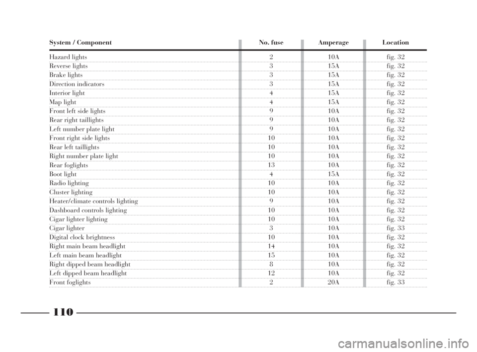
110
fG
System / Component No. fuse Amperage Location
Hazard lights
Reverse lights
Brake lights
Direction indicators
Interior light
Map light
Front left side lights
Rear right taillights
Left number plate light
Front right side lights
Rear left taillights
Right number plate light
Rear foglights
Boot light
Radio lighting
Cluster lighting
Heater/climate controls lighting
Dashboard controls lighting
Cigar lighter lighting
Cigar lighter
Digital clock brightness
Right main beam headlight
Left main beam headlight
Right dipped beam headlight
Left dipped beam headlight
Front foglights
2 10A fig. 32
3 15A fig. 32
3 15A fig. 32
3 15A fig. 32
4 15A fig. 32
4 15A fig. 32
9 10A fig. 32
9 10A fig. 32
9 10A fig. 32
10 10A fig. 32
10 10A fig. 32
10 10A fig. 32
13 10A fig. 32
4 15A fig. 32
10 10A fig. 32
10 10A fig. 32
9 10A fig. 32
10 10A fig. 32
10 10A fig. 32
3 10A fig. 33
10 10A fig. 32
14 10A fig. 32
15 10A fig. 32
8 10A fig. 32
12 10A fig. 32
2 20A fig. 33
4C090-119 ING 13-03-2008 12:51 Pagina 110
Page 114 of 191
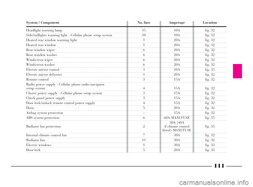
111
fG
Headlight warning lamp
Side/taillights warning light - Cellular phone setup system
Heated rear window warning light
Heated rear window
Rear window wiper
Rear window washer
Windscreen wiper
Windscreen washer
Electric mirror control
Electric mirror defroster
Remote control
Radio power supply - Cellular phone radio-navigator
setup system
Cluster power supply - Cellular phone setup system
Check panel power supply
Door lock/unlock remote control power supply
Horn
Airbag system protection
ABS system protection
Radiator fan protection
Internal climate control fan
Radiator fan
Electric windows
Door lock System / Component No. fuse Amperage Location
15 10A fig. 32
10 10A fig. 32
1 20A fig. 32
1 20A fig. 32
6 20A fig. 32
6 20A fig. 32
6 20A fig. 32
6 20A fig. 32
3 10A fig. 33
1 20A fig. 32
3 15A fig. 32
4 15A fig. 32
3 15A fig. 32
3 15A fig. 32
4 15A fig. 32
5 20A fig. 32
– 15A fig. 32
6 60A-MAXI FUSE fig. 35
30A (40A
2 if climate control fig. 35
fitted)-MAXI FUSE
7 30A fig. 32
11 30A fig. 32
1 30A fig. 33
5 20A fig. 33
4C090-119 ING 13-03-2008 12:51 Pagina 111
Page 136 of 191
133
G
USEFUL ADVICE
FOR LENGTHENING
THE LIFE OF YOUR BATTERY
When you park the car, ensure the
doors, boot and bonnet are closed
properly. The ceiling and map-read-
ing lights must be off.
Do not leave accessories (e.g. radio,
hazard lights, etc.) switched on for a
long time when the engine is not run-
ning.
IMPORTANTIf the battery is left
with a charge of less than 50% for a
long time it will be damaged by sul-
phation, engine startup will deterio-
rate and it will be more subject to
freezing (this may occur at –10°C).
If the car is to be inactive for a long
period of time, refer to the “Storing
the car” paragraph in the “Driving
your car” section.
The liquid in the battery
is poisonous and corrosive.
Do not let it touch the skin
or eyes. Do not bring naked flames
or possible sources of sparks near
to the battery: fire and explosion
risk.
Incorrect fitting of elec-
trical and electronic ac-
cessories can seriously
damage the car.
IMPORTANTWhen removing/in-
stalling the battery, make sure the
battery is mechanically secured cor-
rectly.
Running the car with the
fluid level too low could
damage the battery beyond
repair, even breaking the casing
and allowing the acid contained in
it to leak out completely.
Always wear goggles to
protect the eyes when
working on or near the
battery.
If the car is to remain un-
used for a long period in
very cold weather, remove
the battery and keep it in a warm
place, otherwise it could freeze.
CHECKING THE BATTERY
FLUID LEVEL (electrolyte)
Check the electrolyte level and top
up, if required, at the frequency
shown in the Service Schedule in this
chapter. Have this operation carried
out at a LANCIA Dealership.
4C120-143 ING 11-03-2008 12:01 Pagina 133
Page 137 of 191
134
G
If, after purchasing the vehicle you
want to install electrical accessories
that require a permanent power sup-
ply (alarm, free-hand phone, radio
navigator with satellite anti theft sys-
tem, etc.) go to a LANCIA Dealer-
ship. The qualified staff are able to
suggest the most suitable Lineacces-
sori devices and will assess the over-
all electric absorption, checking
whether the car can sustain the re-
quired load or if an oversized battery
is required.
Remember that these accessories
continue to absorb electrical power
even when the ignition key is removed
(car parked, engine off) and could
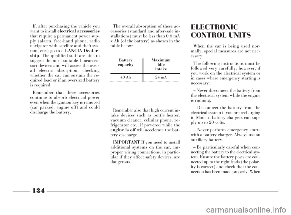
discharge the battery.The overall absorption of these ac-
cessories (standard and after-sale in-
stallations) must be less than 0.6 mA
x Ah (of the battery) as shown in the
table below:ELECTRONIC
CONTROL UNITS
When the car is being used nor-
mally, special measures are not nec-
essary.
The following instructions must be
followed very carefully, however, if
you work on the electrical system or
in cases where emergency starting is
necessary:
– Never disconnect the battery from
the electrical system while the engine
is running.
– Disconnect the battery from the
electrical system if you are recharging
it. Modern battery chargers can sup-
ply up to 20 volts.
– Never perform emergency starts
with a battery charger. Always use an
auxiliary battery.
– Be particularly careful when con-
necting the battery to the electrical sys-
tem. Ensure the battery posts are con-
nected up to the right leads (the polar-
ity is correct) and check that the con-
nection has been made properly. When Remember also that high current in-
take devices such as bottle heater,
vacuum cleaner, cellular phone, re-
frigerator etc., if powered while the
engine is off will accelerate the bat-
tery discharge.
IMPORTANTIf you need to install
additional systems on the car, im-
proper wiring connections, in partic-
ular if they affect safety devices, are
dangerous.
Battery Maximum
capacity idle
intake
40 Ah 24 mA
4C120-143 ING 11-03-2008 12:01 Pagina 134