fuse box Lancia Ypsilon 2002 Owner handbook (in English)
[x] Cancel search | Manufacturer: LANCIA, Model Year: 2002, Model line: Ypsilon, Model: Lancia Ypsilon 2002Pages: 191, PDF Size: 2.45 MB
Page 14 of 191
11
G
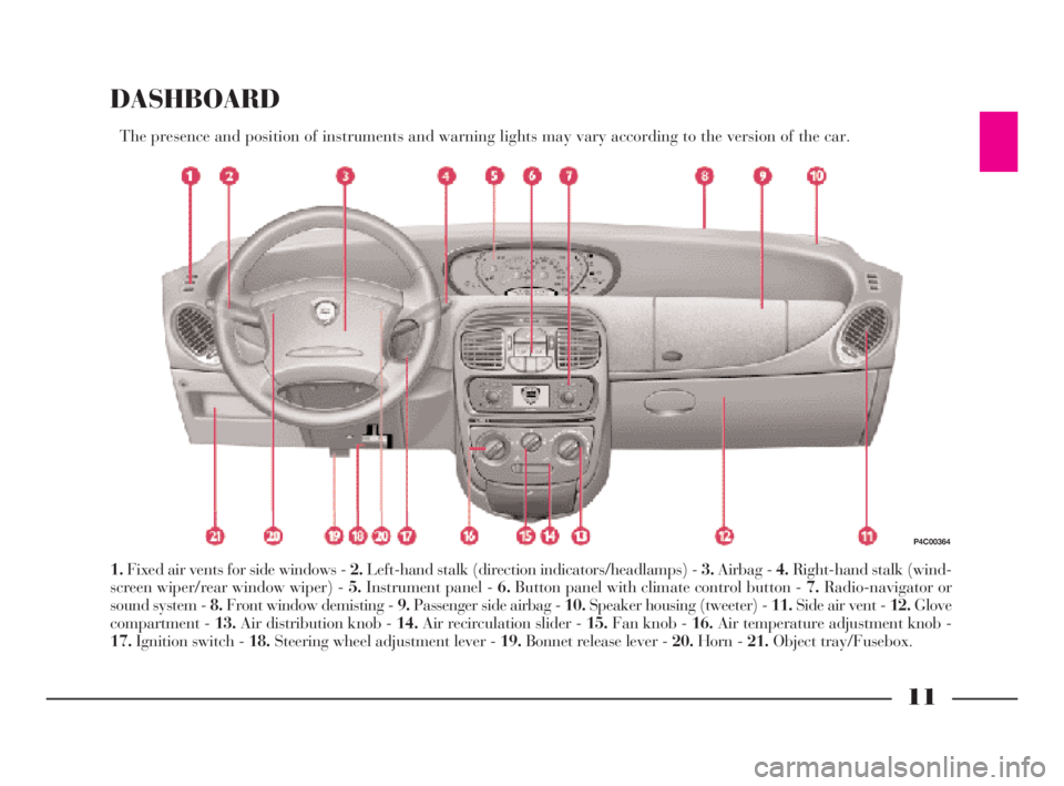
DASHBOARD
The presence and position of instruments and warning lights may vary according to the version of the car.
1.Fixed air vents for side windows - 2.Left-hand stalk (direction indicators/headlamps) - 3.Airbag - 4.Right-hand stalk (wind-
screen wiper/rear window wiper) - 5.Instrument panel - 6.Button panel with climate control button - 7.Radio-navigator or
sound system - 8.Front window demisting - 9.Passenger side airbag - 10.Speaker housing (tweeter) - 11.Side air vent - 12.Glove
compartment - 13.Air distribution knob - 14.Air recirculation slider - 15.Fan knob - 16.Air temperature adjustment knob -
17.Ignition switch - 18.Steering wheel adjustment lever - 19.Bonnet release lever - 20.Horn - 21.Object tray/Fusebox.
P4C00364
4C001-067 ING 11-03-2008 11:57 Pagina 11
Page 15 of 191
12
G
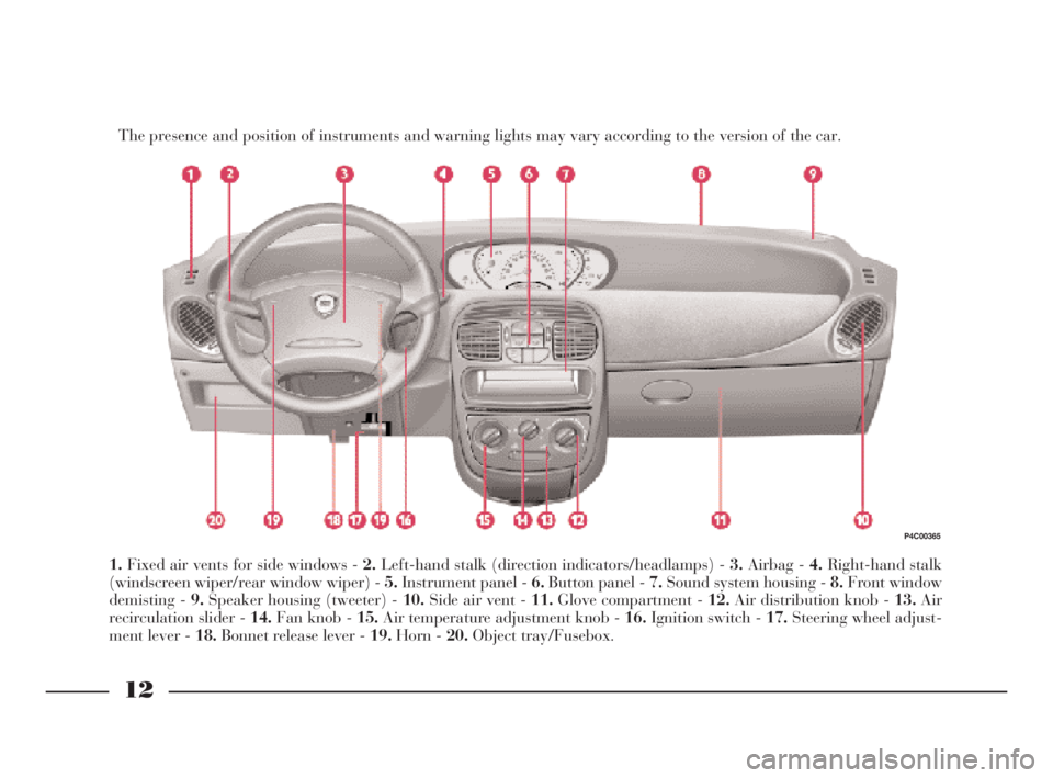
The presence and position of instruments and warning lights may vary according to the version of the car.
1.Fixed air vents for side windows - 2.Left-hand stalk (direction indicators/headlamps) - 3.Airbag - 4.Right-hand stalk
(windscreen wiper/rear window wiper) - 5.Instrument panel - 6.Button panel - 7.Sound system housing - 8.Front window
demisting - 9.Speaker housing (tweeter) - 10.Side air vent - 11.Glove compartment - 12.Air distribution knob - 13.Air
recirculation slider - 14.Fan knob - 15.Air temperature adjustment knob - 16.Ignition switch - 17.Steering wheel adjust-
ment lever - 18.Bonnet release lever - 19.Horn - 20.Object tray/Fusebox.
P4C00365
4C001-067 ING 11-03-2008 11:57 Pagina 12
Page 69 of 191
66
G
CELLULAR PHONE
SETUP
If the car has been ordered to in-
clude provision for the fitting of cel-
lular phones, it will have:
– one dual purpose speaker (sound
system and cellular phone) located in
the right-hand door;
– one dual purpose aerial (sound
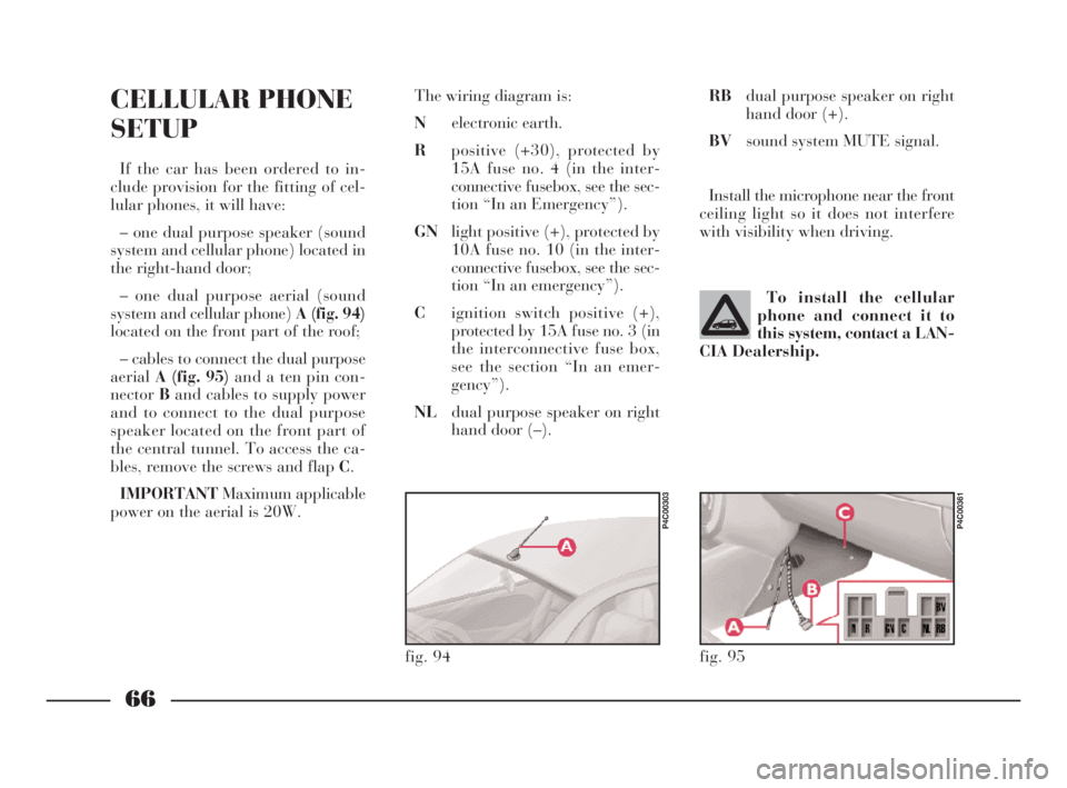
system and cellular phone) A (fig. 94)
located on the front part of the roof;
– cables to connect the dual purpose
aerialA (fig. 95)and a ten pin con-
nectorBand cables to supply power
and to connect to the dual purpose
speaker located on the front part of
the central tunnel. To access the ca-
bles, remove the screws and flap C.
IMPORTANTMaximum applicable
power on the aerial is 20W.The wiring diagram is:
Nelectronic earth.
Rpositive (+30), protected by
15A fuse no. 4 (in the inter-
connective fusebox, see the sec-
tion “In an Emergency”).
GNlight positive (+), protected by
10A fuse no. 10 (in the inter-
connective fusebox, see the sec-
tion “In an emergency”).
Cignition switch positive (+),
protected by 15A fuse no. 3 (in
the interconnective fuse box,
see the section “In an emer-
gency”).
NLdual purpose speaker on right
hand door (–).To install the cellular
phone and connect it to
this system, contact a LAN-
CIA Dealership.
fig. 94
P4C00303
RBdual purpose speaker on right
hand door (+).
BVsound system MUTE signal.
Install the microphone near the front
ceiling light so it does not interfere
with visibility when driving.
fig. 95
P4C00361
4C001-067 ING 11-03-2008 11:57 Pagina 66
Page 110 of 191
Before replacing a fuse,
make sure the key has
been taken out from the ig-
nition and that all users are
switched off or deactivated.
107
fG
BOOT LIGHT
To change the 12V-5W (type C5W)
bulb, remove the lens A (fig. 28), by
pushing it in the direction of the arrow.IF A FUSE BLOWS
GENERAL
The fuse is an element for protecting
the electrical system. It will blow (that
it will break) in the event of a failure
or incorrect interventions on the elec-
trical system.
If an electrical device is not working,
check whether the respective fuse is
blown. The conductor should not be
broken. If it is, replace it with another
with the same amperage (same
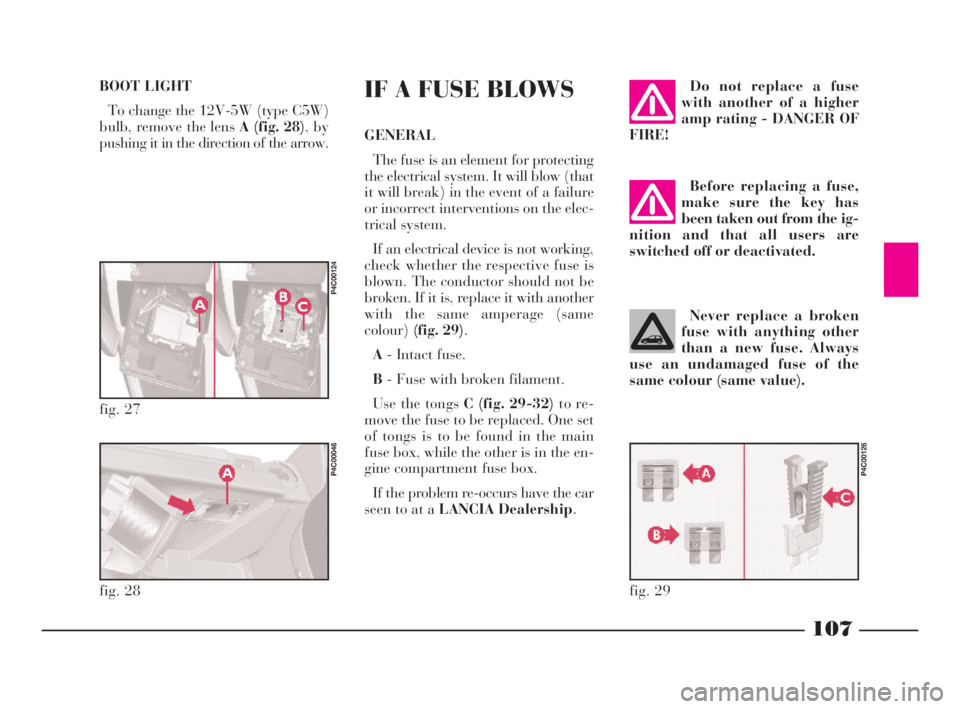
colour)(fig. 29).
A- Intact fuse.
B- Fuse with broken filament.
Use the tongs C (fig. 29-32)to re-
move the fuse to be replaced. One set
of tongs is to be found in the main
fuse box, while the other is in the en-
gine compartment fuse box.
If the problem re-occurs have the car
seen to at a LANCIA Dealership.
Do not replace a fuse
with another of a higher
amp rating - DANGER OF
FIRE!
Never replace a broken
fuse with anything other
than a new fuse. Always
use an undamaged fuse of the
same colour (same value).
fig. 27
P4C00124
fig. 28
P4C00046
fig. 29
P4C00126
4C090-119 ING 13-03-2008 12:51 Pagina 107
Page 111 of 191
108
fG
POSITION OF FUSES
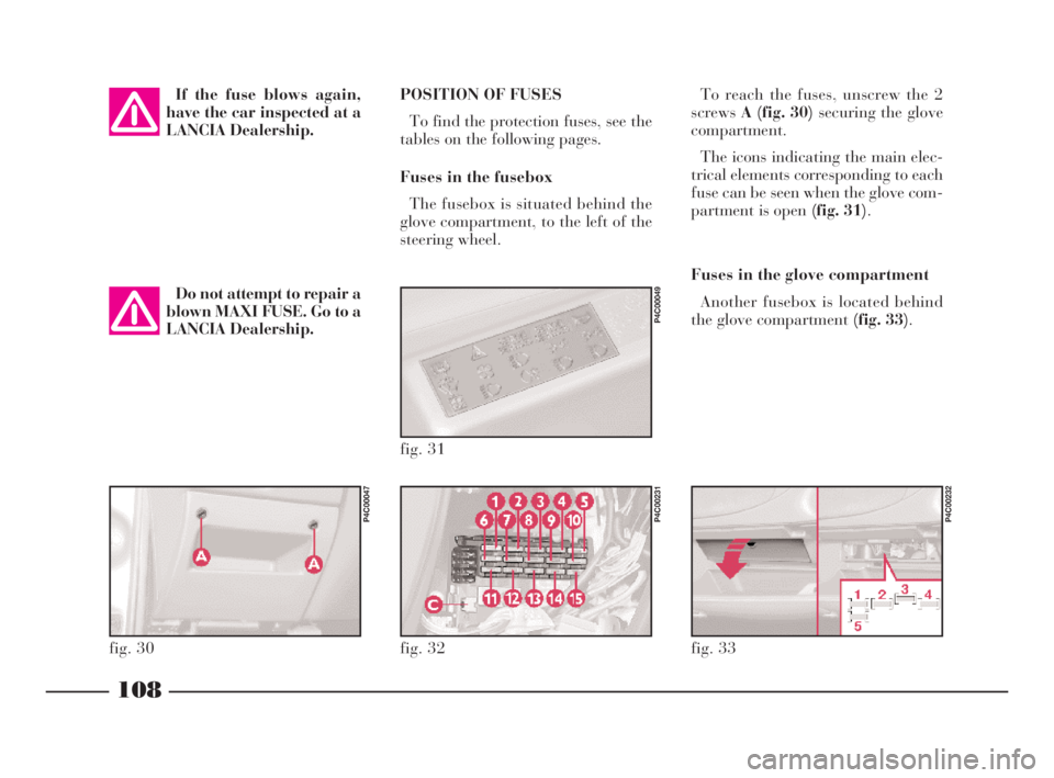
To find the protection fuses, see the
tables on the following pages.
Fuses in the fusebox
The fusebox is situated behind the
glove compartment, to the left of the
steering wheel.To reach the fuses, unscrew the 2
screwsA (fig. 30) securing the glove
compartment.
The icons indicating the main elec-
trical elements corresponding to each
fuse can be seen when the glove com-
partment is open (fig. 31).
Fuses in the glove compartment
Another fusebox is located behind
the glove compartment (fig. 33).
fig. 32
P4C00231
fig. 33
P4C00232
fig. 31
P4C00049
fig. 30
P4C00047
If the fuse blows again,
have the car inspected at a
LANCIA Dealership.
Do not attempt to repair a
blown MAXI FUSE. Go to a
LANCIA Dealership.
4C090-119 ING 13-03-2008 12:51 Pagina 108
Page 112 of 191
109
fG
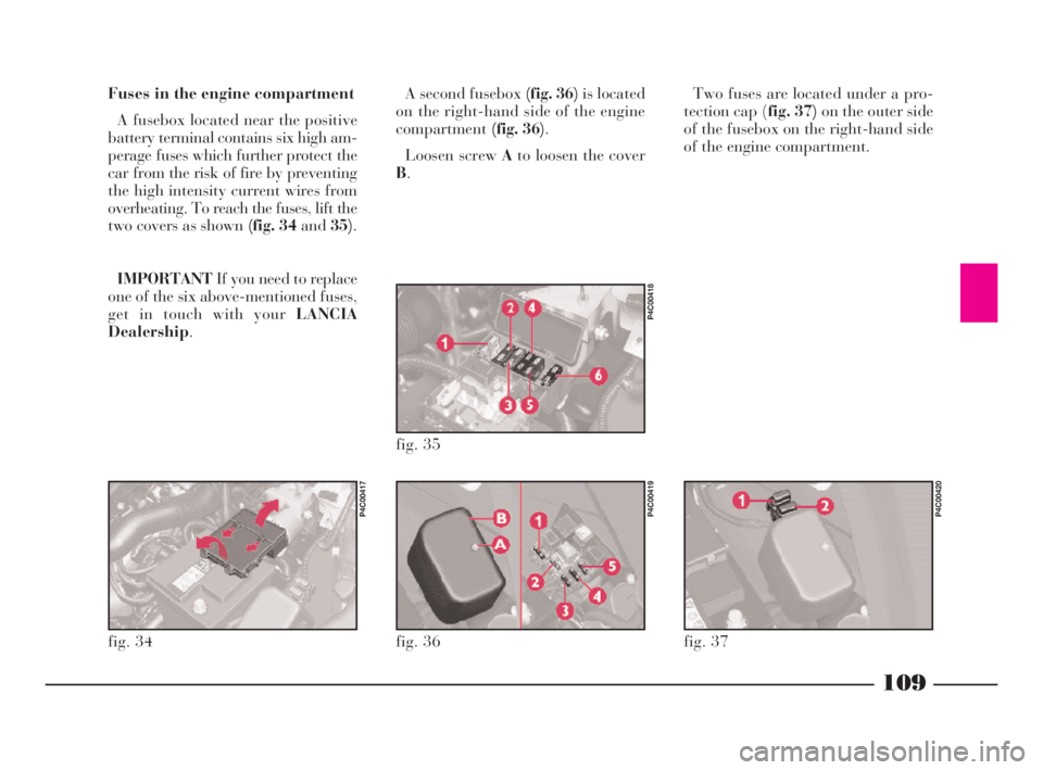
Fuses in the engine compartment
A fusebox located near the positive
battery terminal contains six high am-
perage fuses which further protect the
car from the risk of fire by preventing
the high intensity current wires from
overheating. To reach the fuses, lift the
two covers as shown (fig. 34 and35).
IMPORTANTIf you need to replace
one of the six above-mentioned fuses,
get in touch with your LANCIA
Dealership.A second fusebox (fig. 36)is located
on the right-hand side of the engine
compartment(fig. 36).
Loosen screw Ato loosen the cover
B.Two fuses are located under a pro-
tection cap (fig. 37)on the outer side
of the fusebox on the right-hand side
of the engine compartment.
fig. 34
P4C00417
fig. 36
P4C00419
fig. 37
P4C00420
fig. 35
P4C00418
4C090-119 ING 13-03-2008 12:51 Pagina 109
Page 115 of 191
112
fG
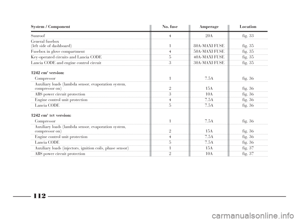
System / Component No. fuse Amperage Location
Sunroof
General fusebox
(left side of dashboard)
Fusebox in glove compartment
Key-operated circuits and Lancia CODE
Lancia CODE and engine control circuit
1242 cm
3version:
Compressor
Auxiliary loads (lambda sensor, evaporation system,
compressor on)
ABS power circuit protection
Engine control unit protection
Lancia CODE
1242 cm
316Vversion:
Compressor
Auxiliary loads (lambda sensor, evaporation system,
compressor on)
Engine control unit protection
Lancia CODE
Auxiliary loads (injectors, ignition coils, phase sensor)
ABS power circuit protection4 20A fig. 33
1 80A-MAXI FUSE fig. 35
4 50A-MAXI FUSE fig. 35
5 40A-MAXI FUSE fig. 35
3 30A-MAXI FUSE fig. 35
1 7.5A fig. 36
2 15A fig. 36
3 10A fig. 36
4 7.5A fig. 36
5 7.5A fig. 36
1 7.5A fig. 36
2 15A fig. 36
4 7.5A fig. 36
5 7.5A fig. 36
1 15A fig. 37
2 10A fig. 37
les
00
ed
az-
ve
4C090-119 ING 13-03-2008 12:51 Pagina 112
Page 172 of 191

169
G
SOUND SYSTEM/RADIO NAVIGATION SYSTEM
SET-UP SYSTEM WIRING
DIAGRAM AND ADDITIONAL
BRANCHES (SOUND SYSTEM)
(fig. 1)
A- Radio aerial;
B- Terminal box;
C- High-amp fuse box;
D- Front left speaker;
E- Left tweeter;
F- Right tweeter;
G- Front right speaker;
H- Radio;
I- Rear right speaker;
L- Rear left speaker;
M- CD CHANGER (where fitted)
wire with respectiving connector,
where you can install a compatible
CD CHANGER if required;
m- +30;
n- Code positive;
o- Radio lights positive.
List of cable colour codes
N=Black - R=Red - AG=Blue/Yellow - AR=Blue/Red - CV=Orange/Green
CN=Orange/Black - BN=White-Black - GN=Yellow-Black - NZ=Black-Purple
RG=Red-Yellow - RN=Red-Black - SN=Red-Black
fig. 1
P4C00388
4C168-176 ING 11-03-2008 12:03 Pagina 169
Page 173 of 191

170
G
List of cable colour codes
G=Yellow - N=Black - R=Red - AG=Blue/Yellow - AR=Blue/Red - BR=White/Red -
CV=Orange/Green - CN=Orange/Black - BN=White-Black - GN=Yellow-Black -
NZ=Black-PurpleRG=Red-Yellow - RN=Red-Black - SN=Red-Black
SET-UP SYSTEM WIRING
DIAGRAM AND ADDITIONAL
BRANCHES (RADIO
NAVIGATION SYSTEM) (fig. 2)
A- Radio aerial;
B- Terminal box;
C- High-amp fuse box;
D- Front left speaker;
E- Left tweeter;
F- Right tweeter;
G- Front right speaker;
H- Radio-navigator;
I- Rear right speaker;
L- Rear left speaker;
M- Vehicle speed signal;
N- GPS aerial;
O- Reversing signal;
P- CD CHANGER wire with re-
spectiving connector, where you can
install a compatible CD CHANGER if
required;
m- +30;
n- +15;
o- Radio lights positive.
fig. 2
P4C00423
4C168-176 ING 11-03-2008 12:03 Pagina 170
Page 174 of 191

171
G
COMPONENT LOCATION
(SOUND SYSTEM AND RADIO
NAVIGATION SYSTEM) (fig. 3)
1- Front speaker on dashboard
(tweeter) and in doors (mid-
range/woofer)
2- Sound system or radio navigation
system
3- Rear speaker (woofer)
4- Radio aerial
5- Maxi fusebox
6- Fusebox
7- CD-CHANGER wire (in the car
radio set version, only where pro-
vided)
8- GPS aerial (radio navigation sys-
tem only).
fig. 3
P4C00426
4C168-176 ING 11-03-2008 12:03 Pagina 171