dashboard Lancia Ypsilon 2002 Owner handbook (in English)
[x] Cancel search | Manufacturer: LANCIA, Model Year: 2002, Model line: Ypsilon, Model: Lancia Ypsilon 2002Pages: 191, PDF Size: 2.45 MB
Page 13 of 191
You are recommended to read this chapter sit-
ting comfortably in your new Lancia Y. In this
way you will be able to identify the parts de-
scribed immediate and see for yourself what you
have just read.
In short, you will increase your knowledge of your
Lancia Y with its controls and other devices. Later,
when you start the engine and join the traffic you
will make a host of other pleasant discoveries.
DASHBOARD................................................. 11
THE LANCIA CODE SYSTEM....................... 13
IGNITION SWITCH ........................................ 16
INDIVIDUAL SETTINGS ............................... 17
SEAT BELTS .................................................. 21
TRANSPORTING CHILDREN SAFELY .......... 26
INSTRUMENT PANEL ................................... 29
INSTRUMENTS............................................. 31
WARNING LIGHTS ........................................ 34HEATING AND VENTILATION ..................... 37
CLIMATE CONTROL SYSTEM....................... 40
STEERING COLUMN STALKS ...................... 41
CONTROLS.................................................... 43
INTERIOR EQUIPMENT ................................ 45
SUNROOF...................................................... 48
DOORS........................................................... 49
BOOT ............................................................. 51
BONNET........................................................ 53
SKI AND ROOF RACKS................................. 55
HEADLIGHTS............................................... 55
ABS ................................................................ 56
FRONT AND SIDE AIRBAGS.......................... 58
EOBD SYSTEM............................................... 63
SOUND SYSTEM ........................................... 64
RADIO-NAVIGATION SYSTEM..................... 65
CELLULAR PHONE SETUP........................... 66
FUEL TANK CAP ............................................ 67
10
G
GETTING TO KNOW YOUR CAR
4C001-067 ING 11-03-2008 11:57 Pagina 10
Page 14 of 191
11
G
DASHBOARD
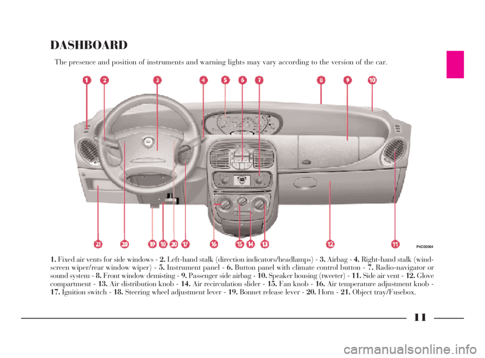
The presence and position of instruments and warning lights may vary according to the version of the car.
1.Fixed air vents for side windows - 2.Left-hand stalk (direction indicators/headlamps) - 3.Airbag - 4.Right-hand stalk (wind-
screen wiper/rear window wiper) - 5.Instrument panel - 6.Button panel with climate control button - 7.Radio-navigator or
sound system - 8.Front window demisting - 9.Passenger side airbag - 10.Speaker housing (tweeter) - 11.Side air vent - 12.Glove
compartment - 13.Air distribution knob - 14.Air recirculation slider - 15.Fan knob - 16.Air temperature adjustment knob -
17.Ignition switch - 18.Steering wheel adjustment lever - 19.Bonnet release lever - 20.Horn - 21.Object tray/Fusebox.
P4C00364
4C001-067 ING 11-03-2008 11:57 Pagina 11
Page 44 of 191
41
G
IMPORTANTThe climate control
is very useful for speeding up demist-
ing because it dries the air. Simply
adjust the controls for the demisting
function and turn on the climate con-
trol by pressing button
√.
IMPORTANTThe versions with cli-
mate control have a factory-fitted
pollen filter.
IMPORTANTThe climate control
compressor will be temporarily ex-
cluded when accelerating sharply, and
reengaged after an established period
of time.STEERING
COLUMN STALKS
LEFT-HAND STALK
This stalk controls the following out-
side lights:
– side/taillights;
– dipped beam headlights;
– main beam headlights;
– direction indicators.
The outside lights can only be lit up
with the control stalk when the igni-
tion key is at MAR.
When the outside lights are turned
on, the instrument panel and the var-
ious controls located in the dashboard
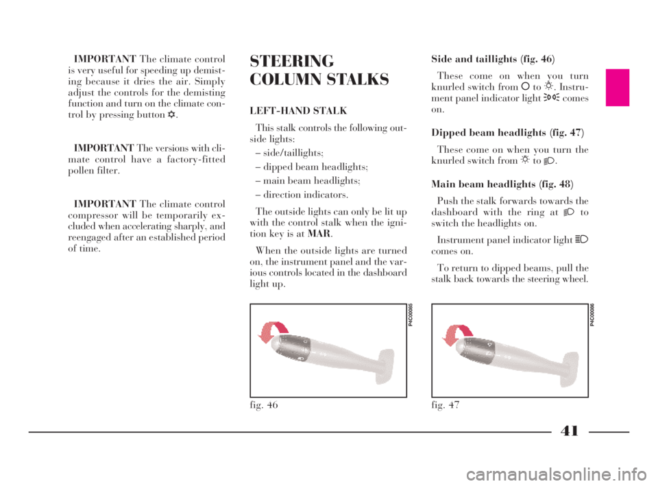
light up.Side and taillights (fig. 46)
These come on when you turn
knurled switch from åto6. Instru-
ment panel indicator light 3comes
on.
Dipped beam headlights (fig. 47)
These come on when you turn the
knurled switch from 6to
2.
Main beam headlights (fig. 48)
Push the stalk forwards towards the
dashboard with the ring at
2to
switch the headlights on.
Instrument panel indicator light 1
comes on.
To return to dipped beams, pull the
stalk back towards the steering wheel.
fig. 46
P4C00085
fig. 47
P4C00086
4C001-067 ING 11-03-2008 11:57 Pagina 41
Page 61 of 191

58
G
FRONT AND SIDE
AIRBAGS
FRONT AIRBAGS (fig. 85)
Description and operation
The front airbag (driver and pas-
senger) is a safety device which is im-
mediately triggered in the event of a
front impact.
It consists of an instantly inflatable
bag housed in a special compartment
located:
– in the centre of the steering wheel
on the driver’s side;
– in the dashboard on the passen-
ger’s side (larger bag).
The front airbag (driver and pas-
senger) is a device which protects the
occupants of the car during a head-on
collision of a medium-high degree.
The system was designed to protect
from injury caused by the body crash-
ing to the steering wheel or the dash-
board. IMPORTANTCars fitted with ABS
must always be fitted with the wheel
rims, tyres and brake linings of the
type and make recommended by the
Manufacturer.
The system also includes the EBD
electronic brake correction (Electronic
Brake Distributor) which, through the
control unit and the ABSsensors fur-
ther enhances the braking system.
The car is fitted with an
electronic brake distribu-
tor (EBD). If warning lights
>andxlight up simultaneously
when the engine is running, this
indicates an EBD fault. This
means that violent braking could
cause early locking of the rear
wheels causing the car to skid.
Drive very carefully to the nearest
LANCIA Dealership to have the
system checked.
If only warning light >
switches on when the en-
gine is running, this usu-
ally indicates an ABS fault. In such
cases the braking system is still ef-
ficient, although the anti-locking
device does not function. The EBD
system may also be less efficient.
Go to a LANCIA Dealership imme-
diately, taking care not to brake
suddenly, and have the system
checked.
If the xbrake fluid low
warning light comes on,
stop the car immediately
and contact the nearest LANCIA
Dealership. Fluid leaks from the
hydraulic system, can compromise
brake system operation, both tra-
ditional systems and systems with
ABS.
4C001-067 ING 11-03-2008 11:57 Pagina 58
Page 65 of 191
62
G
It is important to remem-
ber that the airbag can be
fired even when the engine
is not running and the key is at
MAR if it is hit by another vehicle
travelling at suitable speed. As a
consequence, LANCIA recom-
mends sitting children in their
specific restraint systems on the
back seat, which is the most pro-
tected position possible. On the
contrary, the airbags will not be
fired if the car is crashed into
when the key is not inserted or
turned. Consequently, in this case,
the fact that the system is not fired
does not indicate a fault.Always drive with both
hands on the rim of the
steering wheel so that the
airbag is free to inflate during a
head-on collision, and protect you
from serious injury. Do not drive
with your body bending towards
the steering wheel, but sit in an
upright position with your back
resting against the seat.
If an attempt has been
made to steal the car, or if
it has actually been stolen
or has been vandalised in any way
or subjected to flooding, have the
airbag system checked over at a
LANCIA Dealership. Do not apply stickers or
other objects to the steering
wheel or to the dashboard
on the passenger’s side. Do not
travel with objects on your lap or in
front of you nor with a pipe, pencil
or similar between your lips; you
could seriously hurt yourself if the
airbag inflates in a collision.
The correct operation of
front airbags, side airbags
and pretensioners is en-
sured only if the car is not over-
loaded. Do not exceed the maximum
permitted loads (see “Weights” in
“Technical specifications”).When the passenger’s
front airbag is active (pas-
senger front airbag deacti-
vation switch at ON), the warn-
ing light will come on for approx-
imately four seconds and flash for
other four seconds when the igni-
tion key is turned to MAR to re-
mind the driver than the passen-
ger’s front and side airbags (where
fitted) will be fired in the event of
a crash. The warning light should
go out immediately afterwards.
The airbag does not re-
place seat belts but rather
increases their effective-
ness. Furthermore, the airbag is
not fired in the event of low speed
front collisions, side collisions,
rear-end shunts and roll-overs. In
these cases, the passengers are
only protected by the seat belts
which for this reason must always
be fastened.
4C001-067 ING 11-03-2008 11:57 Pagina 62
Page 67 of 191

64
G
piece of adhesive tape between the
screwdriver and the dashboard to
avoid damaging the dashboard;
– to install the speakers in the doors,
unscrew the screws A (fig. 90)and re-
move the protective grille.
IMPORTANTIf the sound system
has only two full-range speakers, use
the compartments in the doors. The
compartments in the dashboard
should only be used for the tweeters.
The rear speakers must be housed in
the compartments made in the side
panel trim (fig. 91). The protective
grille is inserted into place.SOUND SYSTEM
fig. 88
P4C00327
fig. 89
P4C00108
– cables for front speakers on dash-
board;
– sound system compartment;
– speaker compartments: front speak-
ers on the dashboard and doors, rear
speakers on the side panels.
The sound system is installed in the
compartment normally occupied by
the object compartment, which can be
removed by pressing the two retain-
ing tabs A (fig. 88).
You will find the power wires and
the wires connecting to the dashboard
speakers there.
The front tweeter speakers should be
housed in the compartments at the
sides of the dashboard (fig. 89):
– use a screwdriver with a fine blade
to lift the press-fitted grille; insert a
fig. 90
P4C00109
Contact a LANCIA Deal-
ership if you want to in-
stall a sound system after
purchasing your car. Their staff
will advise you on how to safe-
guard the life of the battery. Ex-
cessive idle intake can damage the
battery and invalid the battery
warranty as well.
STANDARD EQUIPMENT
All versions are fitted with the fol-
lowing:
– sound system power supply cables;Go to a LANCIA Dealer-
ship to have the aerial wire
installed.
o
-
4C001-067 ING 11-03-2008 11:57 Pagina 64
Page 113 of 191
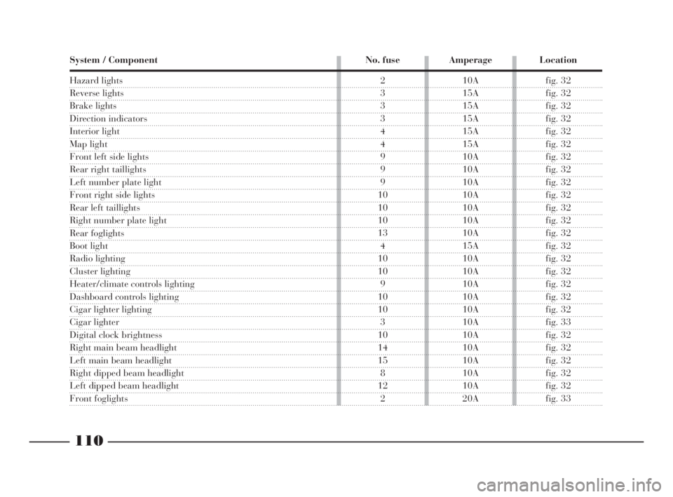
110
fG
System / Component No. fuse Amperage Location
Hazard lights
Reverse lights
Brake lights
Direction indicators
Interior light
Map light
Front left side lights
Rear right taillights
Left number plate light
Front right side lights
Rear left taillights
Right number plate light
Rear foglights
Boot light
Radio lighting
Cluster lighting
Heater/climate controls lighting
Dashboard controls lighting
Cigar lighter lighting
Cigar lighter
Digital clock brightness
Right main beam headlight
Left main beam headlight
Right dipped beam headlight
Left dipped beam headlight
Front foglights
2 10A fig. 32
3 15A fig. 32
3 15A fig. 32
3 15A fig. 32
4 15A fig. 32
4 15A fig. 32
9 10A fig. 32
9 10A fig. 32
9 10A fig. 32
10 10A fig. 32
10 10A fig. 32
10 10A fig. 32
13 10A fig. 32
4 15A fig. 32
10 10A fig. 32
10 10A fig. 32
9 10A fig. 32
10 10A fig. 32
10 10A fig. 32
3 10A fig. 33
10 10A fig. 32
14 10A fig. 32
15 10A fig. 32
8 10A fig. 32
12 10A fig. 32
2 20A fig. 33
4C090-119 ING 13-03-2008 12:51 Pagina 110
Page 115 of 191
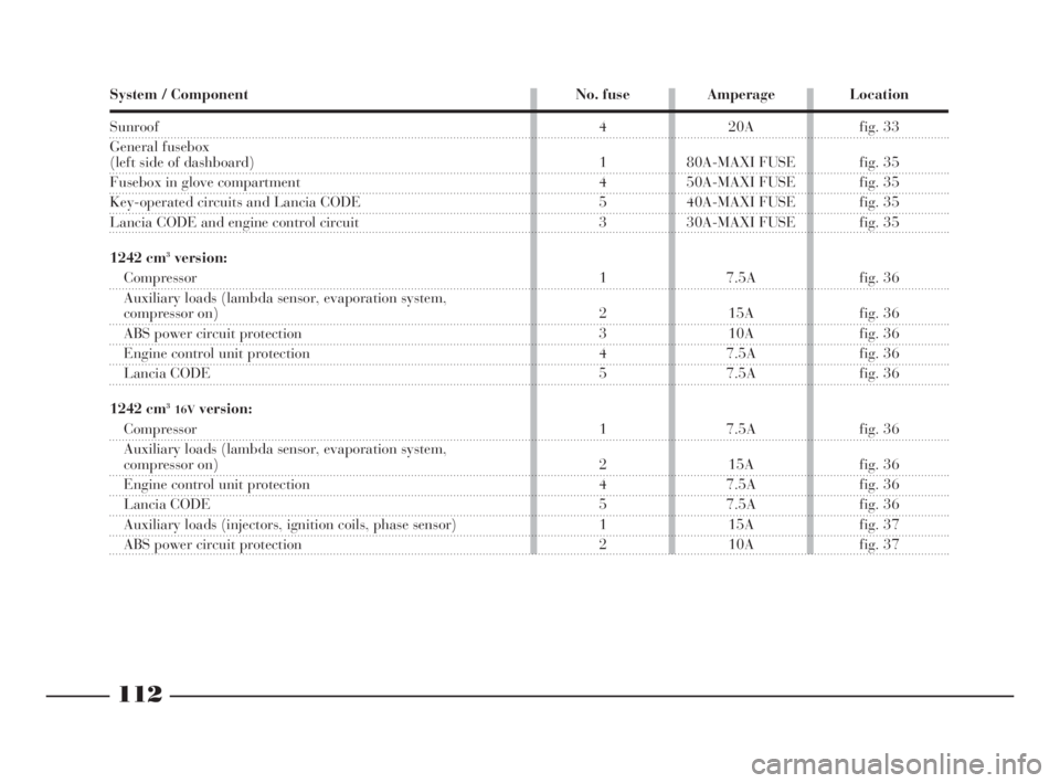
112
fG
System / Component No. fuse Amperage Location
Sunroof
General fusebox
(left side of dashboard)
Fusebox in glove compartment
Key-operated circuits and Lancia CODE
Lancia CODE and engine control circuit
1242 cm
3version:
Compressor
Auxiliary loads (lambda sensor, evaporation system,
compressor on)
ABS power circuit protection
Engine control unit protection
Lancia CODE
1242 cm
316Vversion:
Compressor
Auxiliary loads (lambda sensor, evaporation system,
compressor on)
Engine control unit protection
Lancia CODE
Auxiliary loads (injectors, ignition coils, phase sensor)
ABS power circuit protection4 20A fig. 33
1 80A-MAXI FUSE fig. 35
4 50A-MAXI FUSE fig. 35
5 40A-MAXI FUSE fig. 35
3 30A-MAXI FUSE fig. 35
1 7.5A fig. 36
2 15A fig. 36
3 10A fig. 36
4 7.5A fig. 36
5 7.5A fig. 36
1 7.5A fig. 36
2 15A fig. 36
4 7.5A fig. 36
5 7.5A fig. 36
1 15A fig. 37
2 10A fig. 37
les
00
ed
az-
ve
4C090-119 ING 13-03-2008 12:51 Pagina 112
Page 174 of 191

171
G
COMPONENT LOCATION
(SOUND SYSTEM AND RADIO
NAVIGATION SYSTEM) (fig. 3)
1- Front speaker on dashboard
(tweeter) and in doors (mid-
range/woofer)
2- Sound system or radio navigation
system
3- Rear speaker (woofer)
4- Radio aerial
5- Maxi fusebox
6- Fusebox
7- CD-CHANGER wire (in the car
radio set version, only where pro-
vided)
8- GPS aerial (radio navigation sys-
tem only).
fig. 3
P4C00426
4C168-176 ING 11-03-2008 12:03 Pagina 171
Page 175 of 191

172
G
ELECTRICAL CONNECTION
DIAGRAM (fig. 4)
1- Connection on the branching box
for powering the relays
2- Terminal box
3- Left taillight
4- Relay for the power supply of the
trailer’s left-hand direction indicator
5- Relay for the power supply of the
trailer’s right-hand direction indicator
6- Right taillight
7- 7-pole socket
8- Rear left grounding point
9- Connection between dashboard
cables and rear cables
10- 7.5A fuse
List of cable colour codes
B=White - G- Yellow - L=Blue- M=Brown- N=Black- R=Red- V=Green
TOW HITCH
fig. 4
P4C00170
4C168-176 ING 11-03-2008 12:03 Pagina 172