ESP Lancia Ypsilon 2003 Owner handbook (in English)
[x] Cancel search | Manufacturer: LANCIA, Model Year: 2003, Model line: Ypsilon, Model: Lancia Ypsilon 2003Pages: 191, PDF Size: 2.45 MB
Page 110 of 191
Before replacing a fuse,
make sure the key has
been taken out from the ig-
nition and that all users are
switched off or deactivated.
107
fG
BOOT LIGHT
To change the 12V-5W (type C5W)
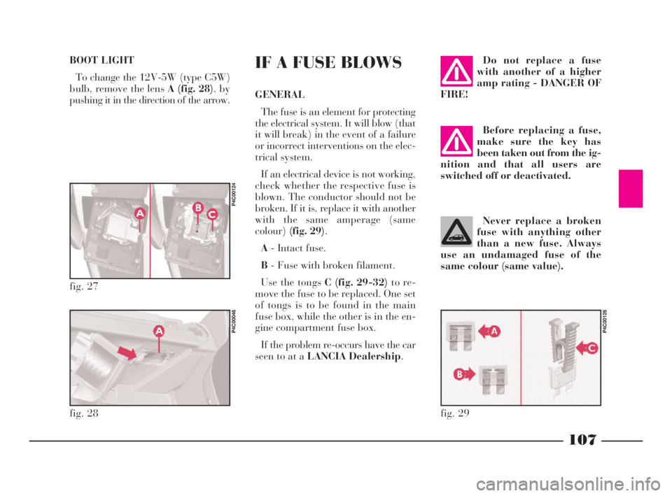
bulb, remove the lens A (fig. 28), by
pushing it in the direction of the arrow.IF A FUSE BLOWS
GENERAL
The fuse is an element for protecting
the electrical system. It will blow (that
it will break) in the event of a failure
or incorrect interventions on the elec-
trical system.
If an electrical device is not working,
check whether the respective fuse is
blown. The conductor should not be
broken. If it is, replace it with another
with the same amperage (same
colour)(fig. 29).
A- Intact fuse.
B- Fuse with broken filament.
Use the tongs C (fig. 29-32)to re-
move the fuse to be replaced. One set
of tongs is to be found in the main
fuse box, while the other is in the en-
gine compartment fuse box.
If the problem re-occurs have the car
seen to at a LANCIA Dealership.
Do not replace a fuse
with another of a higher
amp rating - DANGER OF
FIRE!
Never replace a broken
fuse with anything other
than a new fuse. Always
use an undamaged fuse of the
same colour (same value).
fig. 27
P4C00124
fig. 28
P4C00046
fig. 29
P4C00126
4C090-119 ING 13-03-2008 12:51 Pagina 107
Page 111 of 191
108
fG
POSITION OF FUSES
To find the protection fuses, see the
tables on the following pages.
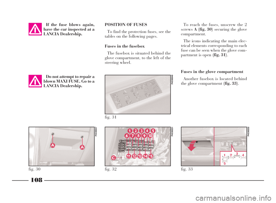
Fuses in the fusebox
The fusebox is situated behind the
glove compartment, to the left of the
steering wheel.To reach the fuses, unscrew the 2
screwsA (fig. 30) securing the glove
compartment.
The icons indicating the main elec-
trical elements corresponding to each
fuse can be seen when the glove com-
partment is open (fig. 31).
Fuses in the glove compartment
Another fusebox is located behind
the glove compartment (fig. 33).
fig. 32
P4C00231
fig. 33
P4C00232
fig. 31
P4C00049
fig. 30
P4C00047
If the fuse blows again,
have the car inspected at a
LANCIA Dealership.
Do not attempt to repair a
blown MAXI FUSE. Go to a
LANCIA Dealership.
4C090-119 ING 13-03-2008 12:51 Pagina 108
Page 128 of 191
125
G
IMPORTANT - Battery
You should check the battery charge
preferably at the beginning of the
winter to avoid the possibility of the
electrolyte freezing up.
This check should be performed
more frequently if the car is mainly
used for short trips, or if it is fitted
with accessories that absorb energy
even when the ignition key is re-
moved, especially if they are after-
market accessories.
You should check the battery fluid
(electrolyte) level more frequently
than shown in the Service Schedule
(see “Car maintenance”) if the car is
used in hot climates or particularly
demanding conditions. IMPORTANT - Engine oil
Change the engine oil more fre-
quently than indicated in the Service
Schedule, if the car is normally driven
in one of the following particularly se-
vere conditions:
– towing a trailer or caravan
– on dusty roads
– short, repetitive trips (less than 7
or 8 kilometres) in outside tempera-
tures below zero
– engines that are frequently left to
idle or drive slowly over long dis-
tances.
IMPORTANT - Air cleaner
Change the air cleaner more often
than indicated in the Service Sched-
ule if you use the car on dusty roads.
If you are in doubt about how often
the engine oil or the air cleaner should
be changed in relation to how you use
the car, contact a LANCIA Dealer-
ship.IMPORTANT - Pollen filter
If the car is often used in dusty or
highly polluted areas, you should
change the pollen filtering element
more frequently, especially if you no-
tice that the amount of air entering
the passenger compartment is re-
duced.
IMPORTANT - Remote control
If the LED on the remote control
unit flashes only once when you press
the remote control button, you need
to replace the batteries.
4C120-143 ING 11-03-2008 12:01 Pagina 125
Page 131 of 191
128
G
ENGINE OIL (fig.s 1, 2)
Check the oil level a few minutes
(approx. 5) after the engine has
stopped with the car parked on level
ground.
The oil level must be between the
MINandMAXmarks on the dipstick.
The space between MINandMAX
corresponds to approximately one
litre of oil.If the oil level is near or even below
theMINmark, pour in oil through
the filler hole until it reaches the MAX
mark.
The oil level must never exceed the
MAXmark.
IMPORTANTIf following a regular
check the oil level is over the MAX
line, go to a LANCIA Dealershipto
have the correct level restored.
IMPORTANTAfter adding or
changing the oil, let the engine turn
over for a few seconds and wait a few
minutes after turning it off before you
check the level.ENGINE OIL CONSUMPTION
During the beginning of the car’s life
the engine is be tuned in. Engine oil
consumption can only be considered
stabilised after the first 5,000 - 6,000
km.
IMPORTANTOil consumption de-
pends on the driving style and the
conditions of use.
When the engine is hot,
operate very carefully in-
side the engine compart-
ment: danger of burns. Remember
that, when the engine is hot, the
electric fan could start operating:
danger of injuries.
Do not add oil with dif-
ferent specifications from
the oil already in the en-
gine.
Used engine oil and re-
placed oil filters contain
substances that can harm
the environment. We recommend
you have the car seen to at a LAN-
CIA Dealership for the oil and fil-
ter change. It is suitably equipped
for disposing of used oil and filters
in an environmentally-friendly
way that complies with the law.
4C120-143 ING 11-03-2008 12:01 Pagina 128
Page 135 of 191
BATTERY
The Lancia Y’s battery is of the
“Limited Maintenance” type: under
normal conditions, it requires no top-
ping up with distilled water.
REPLACING THE BATTERY
If required, replace the battery with
a genuine spare part presenting the
same specifications. If a battery with
different specifications is fitted, the
frequencies shown in the Service
Schedule will no longer be valid. Re-
fer to the instructions provided by the
battery manufacturer.
132
G
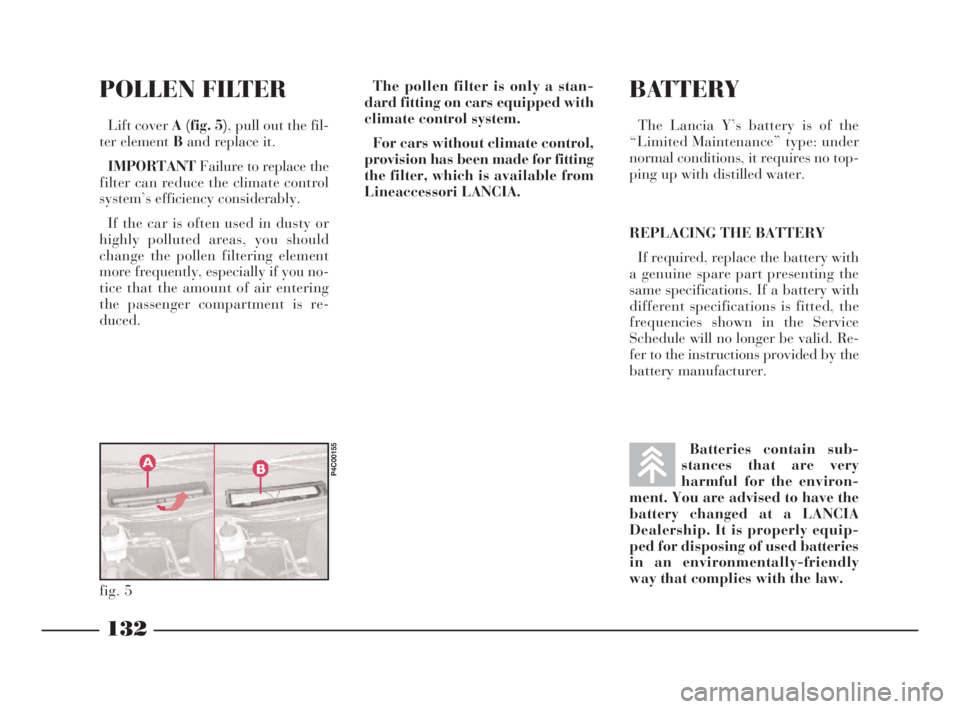
POLLEN FILTER
Lift cover A (fig. 5), pull out the fil-
ter element Band replace it.
IMPORTANTFailure to replace the
filter can reduce the climate control
system’s efficiency considerably.
If the car is often used in dusty or
highly polluted areas, you should
change the pollen filtering element
more frequently, especially if you no-
tice that the amount of air entering
the passenger compartment is re-
duced.The pollen filter is only a stan-
dard fitting on cars equipped with
climate control system.
For cars without climate control,
provision has been made for fitting
the filter, which is available from
Lineaccessori LANCIA.
fig. 5
P4C00155
Batteries contain sub-
stances that are very
harmful for the environ-
ment. You are advised to have the
battery changed at a LANCIA
Dealership. It is properly equip-
ped for disposing of used batteries
in an environmentally-friendly
way that complies with the law.
4C120-143 ING 11-03-2008 12:01 Pagina 132
Page 149 of 191

146
G
BODYWORK PAINT
IDENTIFICATION PLATE
The plate(fig. 4)is fastened to the
inside of the tailgate.
It bears the following data:
A- Paint manufacturer.
B- Colour name.
C- LANCIA colour code.
D- Respray and touch-up code.ENGINE CODE - BODY VERSIONS
fig. 4
P4C00146
Version Engine type code Body version code
1.2 188A4.000 840AF1A 07
1.2
16V188A5.000 840AG1A 08
188A5.000 840AG1A 08B
4C144-167 ING 11-03-2008 12:02 Pagina 146
Page 151 of 191

148
G
FUEL SUPPLY / IGNITION
1.2 versions
Integrated electronic injection and
ignition system: a single electronic
control unit controls both functions.
It processes both the time the injec-
tion lasts (for fuel metering) and the
spark advance angle.
– Type: ......................Multi-point.
– Method of measuring the amount
of aspirated air for petrol metering:
“Speed density” (*).
– “Closed loop”: information on
combustion for correct petrol meter-
ing achieved by means of two lambda
sensors (one upstream and the other
downstream with respect to the catal-
yser).– Electric petrol pump: in-tank.
– Injection pressure: ......... 3.5 bar.
– Air cleaner: dry-type with paper
filter element.
– Firing order: ................1-3-4-2.
– Engine idling speed: 750±50 rpm.
– Spark plugs:
Champion.................RC10YCC
NGK ........................... BKR5EZ1.216Vversions
Integrated electronic injection and
ignition system: a single electronic
control unit controls both functions.
It processes both the time the injec-
tion lasts (for fuel metering) and the
spark advance angle.
– Type: ......................Multi-point.
– Method of measuring the amount
of aspirated air for “Speed density”
petrol metering (*).
– “Closed loop”: information on
combustion for correct petrol meter-
ing achieved by means of two lambda
sensors (one upstream and the other
downstream with respect to the catal-
yser).
– Electric petrol pump: in-tank.
4C144-167 ING 11-03-2008 12:02 Pagina 148
Page 169 of 191

166
G
FUEL
CONSUMPTION -
CO
2EMISSIONS
The fuel consumption values, in
litres x 100 km, indicated in the fol-
lowing tables, have been determined
according to homologation tests pre-
scribed in the European Directive
specifications. The following proce-
dures are used to define the con-
sumption values:Consumption values are defined by
means of the following procedures:
– an urban cycleconsisting of a
cold start and a simulated drive in
city streets;
– an extra-urban cycleconsisting
in frequent accelerations, in all gears,
simulating normal conditions of use.
Speed ranges from 0 to 120 km/h;
– the combined consumptionis
calculated as approximately 37% of
the urban cycle and approximately
63% of the extra-urban cycle. IMPORTANT Road and traffic
conditions, weather, general con-
ditions of the car, driving style, fit-
tings and accessories, use of the
climate control system, load, roof
racks and other situations penal-
ising aerodynamic penetration and
effecting rolling resistance will in-
fluence fuel consumption rates
which can be different from the
values shown in the table (see
“Cheap running that respects the
environment” in “Driving your
car” chapter).
Consumption may be greater during
the first 2000 km due to running in.
Consumption according1.2 1.2 16V1.216VM Nblue
to Directive 1999/100/EC1.216VM
Nred
Urban7.3 7.5 8.3
Extra-urban4.8 5.0 5.5
Combined5.7 6.0 6.5
4C144-167 ING 11-03-2008 12:02 Pagina 166
Page 172 of 191

169
G
SOUND SYSTEM/RADIO NAVIGATION SYSTEM
SET-UP SYSTEM WIRING
DIAGRAM AND ADDITIONAL
BRANCHES (SOUND SYSTEM)
(fig. 1)
A- Radio aerial;
B- Terminal box;
C- High-amp fuse box;
D- Front left speaker;
E- Left tweeter;
F- Right tweeter;
G- Front right speaker;
H- Radio;
I- Rear right speaker;
L- Rear left speaker;
M- CD CHANGER (where fitted)
wire with respectiving connector,
where you can install a compatible
CD CHANGER if required;
m- +30;
n- Code positive;
o- Radio lights positive.
List of cable colour codes
N=Black - R=Red - AG=Blue/Yellow - AR=Blue/Red - CV=Orange/Green
CN=Orange/Black - BN=White-Black - GN=Yellow-Black - NZ=Black-Purple
RG=Red-Yellow - RN=Red-Black - SN=Red-Black
fig. 1
P4C00388
4C168-176 ING 11-03-2008 12:03 Pagina 169