boot Lancia Ypsilon 2003 Owner handbook (in English)
[x] Cancel search | Manufacturer: LANCIA, Model Year: 2003, Model line: Ypsilon, Model: Lancia Ypsilon 2003Pages: 191, PDF Size: 2.45 MB
Page 13 of 191
You are recommended to read this chapter sit-
ting comfortably in your new Lancia Y. In this
way you will be able to identify the parts de-
scribed immediate and see for yourself what you
have just read.
In short, you will increase your knowledge of your
Lancia Y with its controls and other devices. Later,
when you start the engine and join the traffic you
will make a host of other pleasant discoveries.
DASHBOARD................................................. 11
THE LANCIA CODE SYSTEM....................... 13
IGNITION SWITCH ........................................ 16
INDIVIDUAL SETTINGS ............................... 17
SEAT BELTS .................................................. 21
TRANSPORTING CHILDREN SAFELY .......... 26
INSTRUMENT PANEL ................................... 29
INSTRUMENTS............................................. 31
WARNING LIGHTS ........................................ 34HEATING AND VENTILATION ..................... 37
CLIMATE CONTROL SYSTEM....................... 40
STEERING COLUMN STALKS ...................... 41
CONTROLS.................................................... 43
INTERIOR EQUIPMENT ................................ 45
SUNROOF...................................................... 48
DOORS........................................................... 49
BOOT ............................................................. 51
BONNET........................................................ 53
SKI AND ROOF RACKS................................. 55
HEADLIGHTS............................................... 55
ABS ................................................................ 56
FRONT AND SIDE AIRBAGS.......................... 58
EOBD SYSTEM............................................... 63
SOUND SYSTEM ........................................... 64
RADIO-NAVIGATION SYSTEM..................... 65
CELLULAR PHONE SETUP........................... 66
FUEL TANK CAP ............................................ 67
10
G
GETTING TO KNOW YOUR CAR
4C001-067 ING 11-03-2008 11:57 Pagina 10
Page 16 of 191
13
G
THE LANCIA
CODE SYSTEM
To further protect your car from at-
tempted theft, it has been fitted with
an electronic engine immobiliser sys-
tem called “Lancia CODE”, which is
currently considered the most effec-
tive way of protecting your car against
theft.This system is automatically
activated each time the engine is
switched off. Each ignition key, in
fact, contains an electronic device
which modulates a radio-frequency
signal emitted by a special aerial dur-
ing ignition. The modulated signal is
a “password” with which the control
unit recognises the key. Engine igni-
tion is enabled only if the key is recog-
nised by the system.THE KEYS
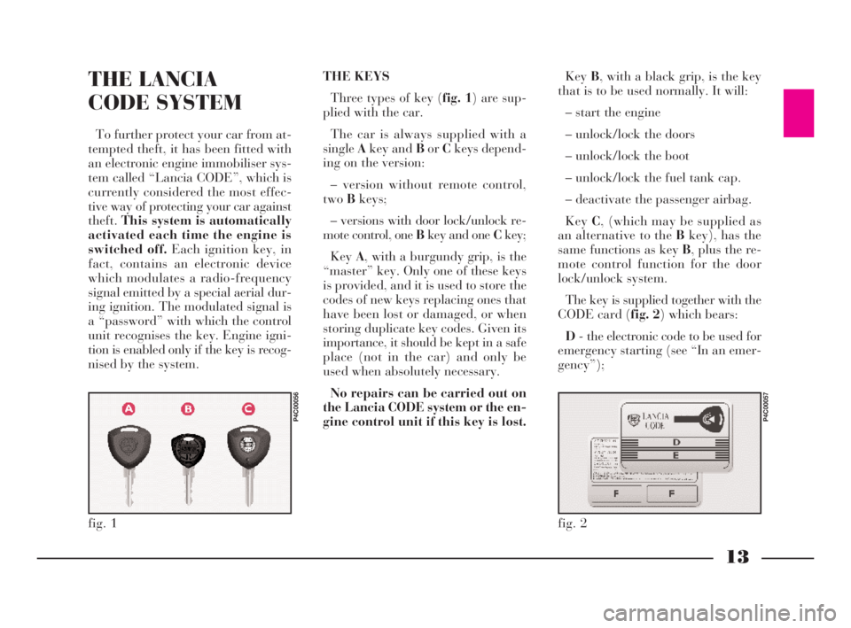
Three types of key (fig. 1) are sup-
plied with the car.
The car is always supplied with a
singleAkey and BorCkeys depend-
ing on the version:
– version without remote control,
twoBkeys;
– versions with door lock/unlock re-
mote control, one Bkey and one Ckey;
KeyA, with a burgundy grip, is the
“master” key. Only one of these keys
is provided, and it is used to store the
codes of new keys replacing ones that
have been lost or damaged, or when
storing duplicate key codes. Given its
importance, it should be kept in a safe
place (not in the car) and only be
used when absolutely necessary.
No repairs can be carried out on
the Lancia CODE system or the en-
gine control unit if this key is lost.KeyB, with a black grip, is the key
that is to be used normally. It will:
– start the engine
– unlock/lock the doors
– unlock/lock the boot
– unlock/lock the fuel tank cap.
– deactivate the passenger airbag.
KeyC, (which may be supplied as
an alternative to the Bkey), has the
same functions as key B, plus the re-
mote control function for the door
lock/unlock system.
The key is supplied together with the
CODE card (fig. 2) which bears:
D- the electronic code to be used for
emergency starting (see “In an emer-
gency”);
fig. 1
P4C00056
fig. 2
P4C00057
4C001-067 ING 11-03-2008 11:57 Pagina 13
Page 54 of 191

51
G
BOOT
OPENING/CLOSING
THE TAILGATE
To open the boot from the outside,
unlock it with the ignition key A
(fig. 72).
To open it from inside the car, pull
leverA (fig. 73)at the side of the dri-
ver’s seat.
To lift the tailgate, use the grip lo-
cated between the two number plate
lights.When the tailgate is closed, it will
lock automatically, and can only be
reopened by using the key or pulling
leverA (fig. 73)inside the car.
IMPORTANTNever leave the keys
in the boot.
Use the handle situated in the inte-
rior trim of the tailgate A (fig. 74)to
lower it without getting your hands
dirty.
To close the tailgate, lower it and
press in the centre until you hear it
lock.
fig. 72
P4C00021
fig. 73
P4C00015
Do not work boot release
lever when the car is in
motion.
The addition of objects to
the rear parcel shelf or
tailgate (loudspeakers,
spoiler, etc.) may prevent the gas-
filled struts at the sides of the tail-
gate working properly. Items
arranged on the rear window shelf
could be thrown forwards and in-
jure passengers should you brake
sharply.
fig. 74
P4C00037
When using the boot,
make sure the load you are
carrying does not exceed
the permitted weight (see the
“Technical specifications” sec-
tion). Also ensure the items in the
boot are arranged properly to pre-
vent them being thrown forward
and injurying passengers should
you brake sharply.
4C001-067 ING 11-03-2008 11:57 Pagina 51
Page 55 of 191

52
G
4)Fold the seat back forwards to
make a flat loading surface with the
boot floor (fig. 78).
If necessary, the cushion can also be
tilted(fig. 79). Consequently, before
releasing the seat back, lift the cush-
ion as shown and tip it against the
front seat backs; the rear seat back-
rest can then be released and tilted
forwards.
To return the seat to its normal po-
sition:
1)Return the seat back to the verti-
cal position and make sure it is prop-
erly locked into place; the red strip on
the hook-up button must disappear.
fig. 77
P4C00034
Removing the parcel shelf
If you wish to remove the parcel
shelf to extend the boot capacity, un-
hook the two tie-rods (one each side)
A (fig. 75)from the hooks B, then
pull the parcel shelf outwards so that
pinsCcome out.
The shelf can then be positioned be-
hind the front seats.INCREASING THE LOAD AREA
Proceed as follows:
1)Make sure that the side seat belts
A (fig. 76)have been inserted into the
corresponding bracket B.
2)Remove the rear head restraints
if required.
3)Release the seat back by pressing
buttonA (fig. 77)(one for each side)
located on the back seat back-rest
(even when a split back seat is fitted);
a red strip will appear on the short
side of the button (towards the inside
of the car) to indicate that it has been
released.
fig. 75
P4C00009
fig. 76
P4C00052
Heavy loads which are
not securely anchored
could seriously injure pas-
sengers in the event of an accident.
4C001-067 ING 11-03-2008 11:57 Pagina 52
Page 56 of 191
53
G
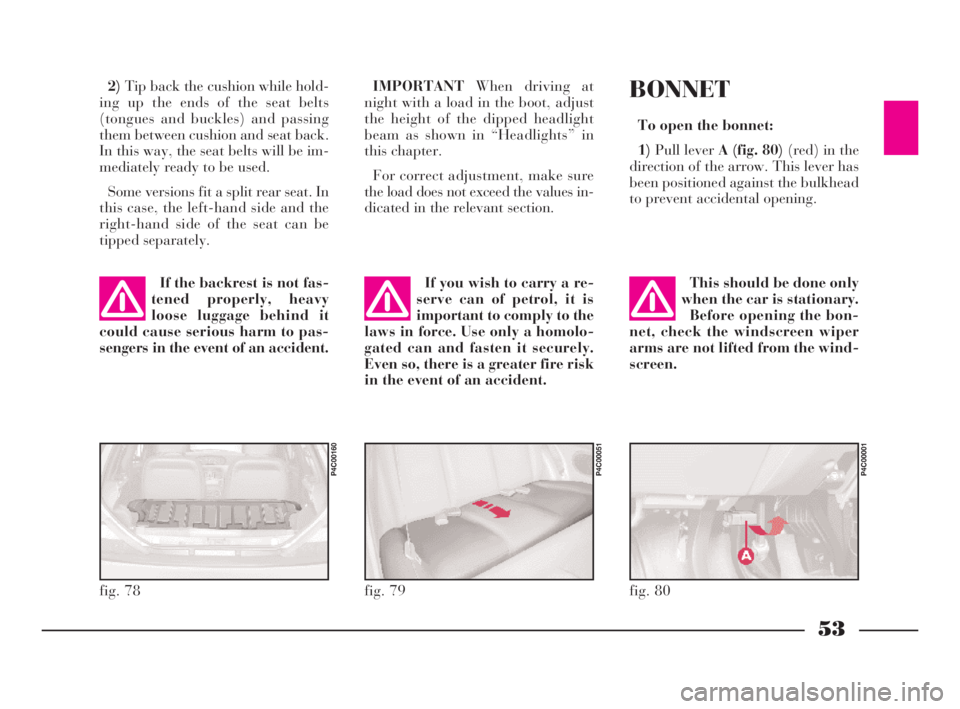
2)Tip back the cushion while hold-
ing up the ends of the seat belts
(tongues and buckles) and passing
them between cushion and seat back.
In this way, the seat belts will be im-
mediately ready to be used.
Some versions fit a split rear seat. In
this case, the left-hand side and the
right-hand side of the seat can be
tipped separately.IMPORTANTWhen driving at
night with a load in the boot, adjust
the height of the dipped headlight
beam as shown in “Headlights” in
this chapter.
For correct adjustment, make sure
the load does not exceed the values in-
dicated in the relevant section.
fig. 78
P4C00160
fig. 79
P4C00051
If the backrest is not fas-
tened properly, heavy
loose luggage behind it
could cause serious harm to pas-
sengers in the event of an accident.If you wish to carry a re-
serve can of petrol, it is
important to comply to the
laws in force. Use only a homolo-
gated can and fasten it securely.
Even so, there is a greater fire risk
in the event of an accident.
BONNET
To open the bonnet:
1)Pull lever A (fig. 80)(red) in the
direction of the arrow. This lever has
been positioned against the bulkhead
to prevent accidental opening.
fig. 80
P4C00001
This should be done only
when the car is stationary.
Before opening the bon-
net, check the windscreen wiper
arms are not lifted from the wind-
screen.
4C001-067 ING 11-03-2008 11:57 Pagina 53
Page 58 of 191
55
G
SKI AND
ROOF RACKS
ANCHORAGE HOOKS
POSITIONING
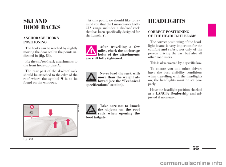
The hooks can be reached by slightly
moving the door seal in the points in-
dicated in (fig. 83).
Fix the ski/roof rack attachments to
the front hook-up pins A.
The rear part of the ski/roof rack
should be attached to the edge of the
roof where the symbol
Vis to be
found on the windows.At this point, we should like to re-
mind you that the Lineaccessori LAN-
CIA range includes a ski/roof rack
that has been specifically designed for
the Lancia Y.
fig. 83
P4C00104
After travelling a few
miles, check the anchorage
bolts of the attachments
are still fully tightened.
Never load the rack with
more than the weight al-
lowed (see the “Technical
specifications” section).
Take care not to knock
the objects on the roof
rack when opening the
boot tailgate.
HEADLIGHTS
CORRECT POSITIONING
OF THE HEADLIGHT BEAMS
The correct positioning of the head-
light beams is very important for the
comfort and safety, not only of the
person driving the car, but also all
other road users.
This is also covered by a specific law.
To ensure you and other drivers
have the best visibility conditions
when travelling with the headlights
on, the headlights must be set pro-
perly.
Have the headlight position checked
at a LANCIA Dealershipand ad-
justed if necessary.
4C001-067 ING 11-03-2008 11:57 Pagina 55
Page 59 of 191

56
G
ABS
The car is fitted with an ABS brak-
ing system that prevents the wheels
locking when braking, it exploits the
grip on the road surface holding the
car in the case of sudden braking.
The driver becomes aware of the
ABS activation through a slight throb-
bing of the brake pedal and the rele-
vant noise it makes.
This does not indicate brake mal-
functioning, it is an indication to the
driver that the ABS is operating. It is
a warning that the car is travelling at
borderline road grip and therefore the
speed should be adjusted to the type
of road surface.
The ABS is an addition to the basic
braking system; in the case of a fail-
ure it disables, leaving the braking
system in the same conditions as a ve-
hicle without ABS installed. COMPENSATION
FOR THE UPWARD SLANT
OF THE HEADLIGHT BEAMS
When the car is loaded, it “slopes”
backwards. This means that the head-
light beam rises. In this case it is nec-
essary to return it to the correct posi-
tion.
The car is fitted with an electric ad-
juster(fig. 84)situated at the side of
the handbrake:
Position0- one or two people on the
front seats.
Position1- five people.
Position2- five people + load in
luggage compartment.
Position3- driver + maximum per-
missible load all in the boot.
fig. 84
P4C00105
Check the positioning of
the headlight beams every
time you change the load
to be carried.
IMPORTANTIn order that the ad-
juster operates properly, the load in
the boot must not exceed the maxi-
mum values indicated.
ADJUSTING THE BEAM
OF THE FRONT FOGLIGHTS
Ask a LANCIA Dealershipto check
and, if necessary, adjust the beam for
you.
4C001-067 ING 11-03-2008 11:57 Pagina 56
Page 68 of 191

65
G
BASIC SOUND SYSTEM -
optional
This consists of the following:
– 2 front tweeter speakers;
– 2 full-range speakers in the doors;
– rear speaker cables;
– wire and manual radio aerial lo-
cated on the front of the roof.
For electrical connec-
tions, see the section “Ac-
cessory installation”.SOUND SYSTEM
The complete system consists of the
following:
– basic system (see previous para-
graph).
– Clarion PU2312 sound system
with CD player (fig. 92)(for charac-
teristics and instructions see attached
supplement).
– case for front panel.
– brackets for removing radio unit.
– 2 rear speakers;
– CD CHANGER (where fitted) wire
with respecting connector located on
right-hand side of the boot, where you
can install a compatible CD
CHANGER if required.
fig. 91
P4C00110
fig. 92
P4C00380
RADIO-NAVIGATION
SYSTEM
The complete system consists of the
following:
– basic system (see previous para-
graph).
– Blaupunkt radio-navigator (fig. 93)
(for characteristics and instructions see
attached supplement).
– brackets for removing radio-navi-
gator unit.
– 2 rear speakers.
– CD CHANGER wire with respect-
ing connector located on right-hand
side of the boot, where you can install
a compatible CD CHANGER if re-
quired.
fig. 93
P4C00422
4C001-067 ING 11-03-2008 11:57 Pagina 65
Page 77 of 191
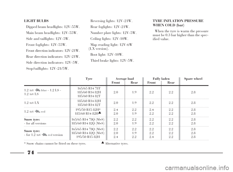
LIGHT BULBS
Dipped beam headlights: 12V-55W.
Main beam headlights: 12V-55W.
Side and taillights: 12V-5W.
Front foglights: 12V-55W.
Front direction indicators: 12V-21W.
Rear direction indicators: 12V-21W.
Side direction indicators: 12V-5W.
Stop/taillights: 12V-21/5W.Reversing lights: 12V-21W.
Rear foglights: 12V-21W.
Number plate lights: 12V-5W.
Ceiling lights: 12V-10W.
Map reading light: 12V-6W
(LX version).
Boot light: 12V-10W.
Third brake lights: 12V-5W.TYRE INFLATION PRESSURE
WHEN COLD (bar)
When the tyre is warm the pressure
must be 0.3 bar higher than the spec-
ified value.
74
G
TyreAverage loadFully laden Spare wheel
Front Rear Front Rear
1.2
16VM Nblue- 1.2 LS - 165/65 R14 78T
1.2
16VLS185/60 R14 82H 2.0 1.9 2.2 2.2 2.8185/60 R14 82T
1.2
16VLX185/60 R14 82H
2.0 1.9 2.2 2.2 2.8185/60 R14 82T
1.2
16VM Nred195/50 R15 82H* 2.4 2.2 2.4 2.2 2.8
185/60 R14 82H▲
2.0 1.9 2.2 2.2 2.8
Snow tyre:165/65 R14 78Q (M+S) 2.2 2.2 2.2 2.2 2.8
- for all versions 185/60 R14 82Q (M+S) 2.0 1.9 2.2 2.2 2.8
Snow tyre:165/65 R14 78Q (M+S) 2.2 2.2 2.2 2.2 2.8
- for 1.2
16VM Nredversion185/60 R14 82Q (M+S) 2.0 1.9 2.2 2.2 2.8195/50 R15 82H 2.4 2.2 2.4 2.2 2.8
* Snow chains cannot be fitted on these tyres.▲
Alternative tyres.
4C068-089 ING 11-03-2008 11:59 Pagina 74
Page 78 of 191
75
G
SAFE DRIVING
In designing the Lancia Y, we made
every effort to come up with a car
able to provide driver and passengers
with top-class levels of safety. Never-
theless it is always the behaviour of
the person at the wheel that deter-
mines road safety.
Below you will find some simple tips
to help you travel in safety under dif-
ferent conditions. You will no doubt
be familiar with many of them al-
ready but it will be useful to read
them all carefully.BEFORE GETTING BEHIND
THE WHEEL
– Make sure all lights including the
headlights are working properly.
– Adjust the position of the seats,
steering wheel, driving and door mir-
rors properly for the best driving po-
sition.
– On long journeys, it is a good idea
to slightly alter the lumber support
and/or seat inclination to vary the
weight on the spine and therefore re-
duce tiredness and strain.
– Carefully adjust the head restraints
so the back of the head and not the
nape of the neck is supported.
– Carefully adjust the height of the
seat belts to suit the wearer’s stature
(see the instructions given in the sec-
tion “Getting to know your car - seat
belts”).
– Make sure that nothing (mats etc.)
get in the way of the pedals.– Make sure that any child restraint
systems (child seats, carriers, etc.) are
properly fixed to the rear seat. Follow
the indications given in “Transport-
ing children safely” in the section
“Getting to know your car”.
– Make sure that objects are care-
fully arranged in the boot so they will
not fly forward if you have to brake
sharply.
– Avord placing light-coloured arti-
cles or papers on the object tray which
may be reflected on the windscreen.
– Do not eat a heavy meal before
travelling. Light eating will help keep
your reflexes prompt. Above all, do
not have anything alcoholic to drink.
The use of some drugs may affect
your driving, read the relevant in-
structions sheet carefully.
Remember to periodically check
what is specified in the “Repeated
checks and checks before long trips”
paragraph given in this section.
4C068-089 ING 11-03-2008 11:59 Pagina 75