lock Lancia Ypsilon 2020 Owner handbook (in English)
[x] Cancel search | Manufacturer: LANCIA, Model Year: 2020, Model line: Ypsilon, Model: Lancia Ypsilon 2020Pages: 200, PDF Size: 4.53 MB
Page 111 of 200

REPLACING AN
EXTERNAL BULB
FRONT LIGHT CLUSTERS
These contain the bulbs for the daytime
running lights (DRL), side lights,
dipped/main beam headlights and
direction indicators.
The bulbs are arranged as follows fig.
83:
Daytime running lights (DRL)
Dipped/main beam headlights and
side lights
Direction indicators
Daytime running lights (DRL)
To replace the bulb, proceed as follows:
remove cover A fig. 83;
turn the snap-fitted bulb holder unit
B fig. 84 anticlockwise, remove bulb
C and replace it;
refit the new bulb then reinsert the
bulb holder B fig. 84 in its housing;
then refit the cover A fig. 83.
Side lights
To replace the bulb, proceed as follows:
remove cover B fig. 83;
remove snap-fitted bulb holder C fig.
85, remove the bulb D and replace it;
refit the new bulb then reinsert
the bulb holder unit C fig. 85 in
its housing;
then refit the cover B fig. 83.
Dipped/main beam headlights
To replace the bulb, proceed as follows:
remove the cover B fig. 83 and
then the snap-fitted bulb holder C fig.
86;
remove bulb D from the connector E
and replace it;
refit the new bulb on the connector
making sure that it is locked correctly,
then reinsert bulb holder C in its
housing;
then refit the cover B fig. 83.
Front direction indicators
To replace the bulb, proceed as follows:
turn the cover C fig. 83
anticlockwise, extract the bulb D fig. 87
from its housing and replace it;
83L0F0033C
84L0F0070C
85L0F0069C
86L0F0068C
109
Page 112 of 200

refit the bulb D in the housing E and
then fit the cover C fig. 83.
Side direction indicators
To replace the bulb, proceed as follows:
adjust the lens A fig. 89 to
compress in the internal catch B, then
pull the unit outwards;
turn the bulb holder C anticlockwise,
extract the bulb and replace it;
refit the bulb holder C in the lens and
turn it clockwise;
refit the cluster making sure that the
internal catch B clips into position.
Front fog lights
(for versions/markets, where provided)
To replace the bulb, proceed as follows:
steer the wheel completely, adjust
the tabs A fig. 89 and remove the
flap B;
adjust the clip C fig. 90 and
disconnect the electrical connector D;
remove the cover E by turning it
clockwise (see the word OFF and the
arrow on the cover);
release the catches F fig. 91
removing them outwards;
release the connector G fig. 92 and
replace the bulb H;
87L0F0071C
88L0F0209C
89L0F0205C
90L0F0206C
91L0F0207C
92L0F0208C
110
IN AN EMERGENCY
Page 113 of 200

refit the new lamp and carry out the
procedure described previously in
reverse.
REAR LIGHT CLUSTERS
These contain the bulbs for the side
lights, brake lights and direction
indicators. The reversing lights and rear
fog lights are located instead in the
rear bumper.
The bulbs are arranged as follows fig.
93:A- Direction indicators
B- Brake lights
Direction indicators/brake lights
Turn the bulb holder in directionO
(open) to replace the bulbs. After
replacing the bulb, turn the bulb holder
in directionC(close).
Side lights
These are LEDs. Contact a Lancia
Dealership for replacement.
THIRD BRAKE LIGHTS
These are located in the tailgate and
are LED lights. Contact a Lancia
Dealership for replacement.
REVERSING LIGHT/REAR FOG
LIGHT
To replace the bulb, proceed as follows:
working from inside the bumper,
turn the bulb holder unit A fig. 94 by a
1/4 turn;
extract the bulb and replace it;
refit the new bulb then reinsert the
bulb holder in its housing.
NUMBER PLATE LIGHTS
To replace the bulbs proceed as
follows:
remove lens A fig. 95;
turn the bulb holder B fig. 96
clockwise, extract the bulb C and
replace it; then refit the lens.
93L0F0034C
94L0F0219C
95L0F0259C
96L0F0214C
111
Page 117 of 200
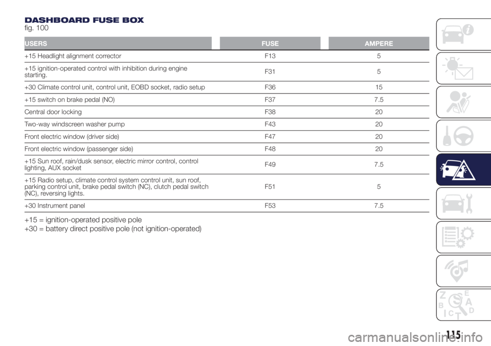
DASHBOARD FUSE BOX
fig. 100
USERSFUSE AMPERE
+15 Headlight alignment corrector F13 5
+15 ignition-operated control with inhibition during engine
starting.F31 5
+30 Climate control unit, control unit, EOBD socket, radio setup F36 15
+15 switch on brake pedal (NO) F37 7.5
Central door locking F38 20
Two-way windscreen washer pump F43 20
Front electric window (driver side) F47 20
Front electric window (passenger side) F48 20
+15 Sun roof, rain/dusk sensor, electric mirror control, control
lighting, AUX socketF49 7.5
+15 Radio setup, climate control system control unit, sun roof,
parking control unit, brake pedal switch (NC), clutch pedal switch
(NC), reversing lights.F51 5
+30 Instrument panel F53 7.5
+15 = ignition-operated positive pole
+30 = battery direct positive pole (not ignition-operated)
115
Page 119 of 200
REPLACING A
WHEEL
129) 130) 131) 132) 133) 134) 135)
54) 55)
JACK
Please note that:
the jack weight is 1,76 kg;
the jack requires no adjustment;
the jack cannot be repaired and in
the event of a fault it must be replaced
by another genuine one;
no tool other than its cranking
device may be fitted on the jack.
CHANGING PROCEDURE
To change a wheel, proceed as follows:
stop the car in a position that is
not dangerous for oncoming traffic
where you can change the wheel safely.
The ground must be flat and sufficiently
compact;
switch off the engine, pull up the
handbrake and engage the 1stgear or
reverse. Wear the reflective safety
jacket (compulsory by law) before
getting out of the car;
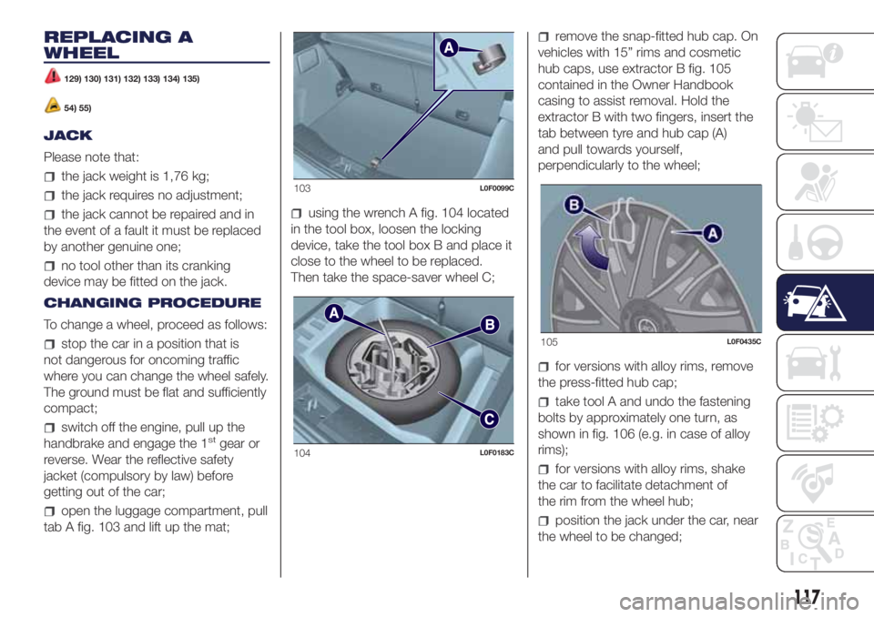
open the luggage compartment, pull
tab A fig. 103 and lift up the mat;
using the wrench A fig. 104 located
in the tool box, loosen the locking
device, take the tool box B and place it
close to the wheel to be replaced.
Then take the space-saver wheel C;
remove the snap-fitted hub cap. On
vehicles with 15” rims and cosmetic
hub caps, use extractor B fig. 105
contained in the Owner Handbook
casing to assist removal. Hold the
extractor B with two fingers, insert the
tab between tyre and hub cap (A)
and pull towards yourself,
perpendicularly to the wheel;
for versions with alloy rims, remove
the press-fitted hub cap;
take tool A and undo the fastening
bolts by approximately one turn, as
shown in fig. 106 (e.g. in case of alloy
rims);
for versions with alloy rims, shake
the car to facilitate detachment of
the rim from the wheel hub;
position the jack under the car, near
the wheel to be changed;
103L0F0099C
104L0F0183C
105L0F0435C
117
Page 121 of 200
fit the standard wheel inserting the 4
bolts into the holes;
using the wrench provided, tighten
the fastening bolts;
lower the vehicle and remove the
jack;
using the wrench provided, fully
tighten the bolts in the sequence
shown previously.
press-fit the wheel cap, aligning the
special splining (on the cap) with the
inflation valve;
place the inner part of the hub cap
on the wheel rim;
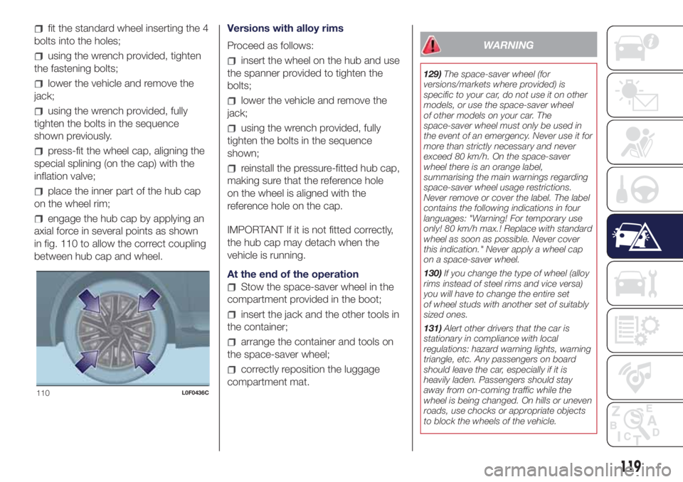
engage the hub cap by applying an
axial force in several points as shown
in fig. 110 to allow the correct coupling
between hub cap and wheel.Versions with alloy rims
Proceed as follows:
insert the wheel on the hub and use
the spanner provided to tighten the
bolts;
lower the vehicle and remove the
jack;
using the wrench provided, fully
tighten the bolts in the sequence
shown;
reinstall the pressure-fitted hub cap,
making sure that the reference hole
on the wheel is aligned with the
reference hole on the cap.
IMPORTANT If it is not fitted correctly,
the hub cap may detach when the
vehicle is running.
At the end of the operation
Stow the space-saver wheel in the
compartment provided in the boot;
insert the jack and the other tools in
the container;
arrange the container and tools on
the space-saver wheel;
correctly reposition the luggage
compartment mat.
WARNING
129)The space-saver wheel (for
versions/markets where provided) is
specific to your car, do not use it on other
models, or use the space-saver wheel
of other models on your car. The
space-saver wheel must only be used in
the event of an emergency. Never use it for
more than strictly necessary and never
exceed 80 km/h. On the space-saver
wheel there is an orange label,
summarising the main warnings regarding
space-saver wheel usage restrictions.
Never remove or cover the label. The label
contains the following indications in four
languages: "Warning! For temporary use
only! 80 km/h max.! Replace with standard
wheel as soon as possible. Never cover
this indication." Never apply a wheel cap
on a space-saver wheel.
130)If you change the type of wheel (alloy
rims instead of steel rims and vice versa)
you will have to change the entire set
of wheel studs with another set of suitably
sized ones.
131)Alert other drivers that the car is
stationary in compliance with local
regulations: hazard warning lights, warning
triangle, etc. Any passengers on board
should leave the car, especially if it is
heavily laden. Passengers should stay
away from on-coming traffic while the
wheel is being changed. On hills or uneven
roads, use chocks or appropriate objects
to block the wheels of the vehicle.
110L0F0436C
119
Page 126 of 200
FUEL CUT-OFF
SYSTEM
147)
FUEL CUT-OFF SYSTEM
This intervenes in the case of an impact
causing:
the interruption of the fuel supply
with the engine consequently cutting
out;
the automatic unlocking of the
doors;
turning on of the lights inside the
vehicle;
the switching on of the hazard
warning lights.
On some versions, the intervention of
the system is indicated by a message
shown on the display.
IMPORTANT Carefully check the vehicle
for fuel leaks, for instance in the engine
compartment, under the vehicle or
near the tank area. After an impact, turn
the ignition key to STOP to prevent the
battery from running down.
To restore the correct operation of the
vehicle, proceed as follows:
turn the ignition key to the MAR
position;
activate the right direction indicator;
deactivate the right direction
indicator;
activate the left direction indicator;
deactivate the left direction indicator;
activate the right direction indicator;
deactivate the right direction
indicator;
activate the left direction indicator;
deactivate the left direction indicator;
ignition key turned to the OFF
position;
turn the ignition key to the MAR-ON
position.
LPG / Natural Power versions:inthe
event of an impact, petrol supply is
immediately cut-off, the LPG safety
valves are closed and the injection is
interrupted, switching off the engine.
WARNING
147)If, after an impact, you smell fuel or
notice leaks from the fuel system, do
not reactivate the system to avoid the risk
of fire.
TOWING THE
VEHICLE
148) 149) 150) 151)
The tow hook, which is supplied with
the vehicle, is housed in the tool box,
under the carpet in the luggage
compartment.
ATTACHING THE TOW
RING
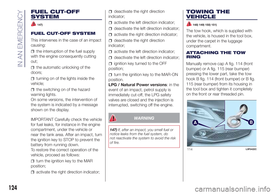
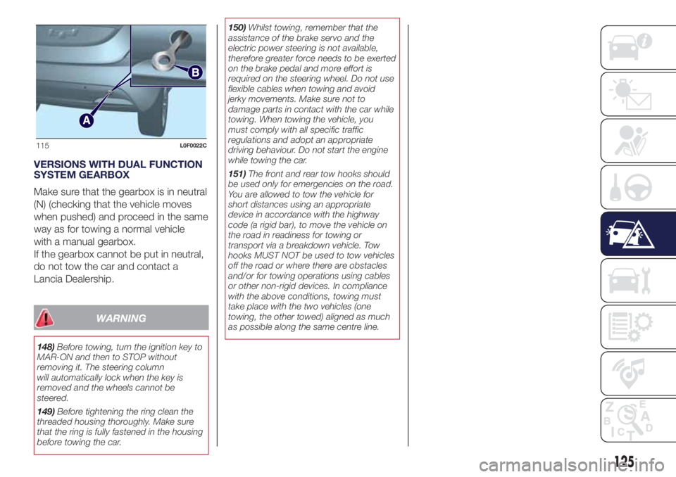
Manually remove cap A fig. 114 (front
bumper) or A fig. 115 (rear bumper)
pressing the lower part, take the tow
hook B fig. 114 (front bumper) or B fig.
115 (rear bumper) from its housing in
the tool box and tighten it completely
on the front or rear threaded pin.
AB
114L0F0422C
124
IN AN EMERGENCY
Page 127 of 200
VERSIONS WITH DUAL FUNCTION
SYSTEM GEARBOX
Make sure that the gearbox is in neutral
(N) (checking that the vehicle moves
when pushed) and proceed in the same
way as for towing a normal vehicle
with a manual gearbox.
If the gearbox cannot be put in neutral,
do not tow the car and contact a
Lancia Dealership.
WARNING
148)Before towing, turn the ignition key to
MAR-ON and then to STOP without
removing it. The steering column
will automatically lock when the key is
removed and the wheels cannot be
steered.
149)Before tightening the ring clean the
threaded housing thoroughly. Make sure
that the ring is fully fastened in the housing
before towing the car.150)Whilst towing, remember that the
assistance of the brake servo and the
electric power steering is not available,
therefore greater force needs to be exerted
on the brake pedal and more effort is
required on the steering wheel. Do not use
flexible cables when towing and avoid
jerky movements. Make sure not to
damage parts in contact with the car while
towing. When towing the vehicle, you
must comply with all specific traffic
regulations and adopt an appropriate
driving behaviour. Do not start the engine
while towing the car.
151)The front and rear tow hooks should
be used only for emergencies on the road.
You are allowed to tow the vehicle for
short distances using an appropriate
device in accordance with the highway
code (a rigid bar), to move the vehicle on
the road in readiness for towing or
transport via a breakdown vehicle. Tow
hooks MUST NOT be used to tow vehicles
off the road or where there are obstacles
and/or for towing operations using cables
or other non-rigid devices. In compliance
with the above conditions, towing must
take place with the two vehicles (one
towing, the other towed) aligned as much
as possible along the same centre line.
115L0F0022C
125
Page 131 of 200
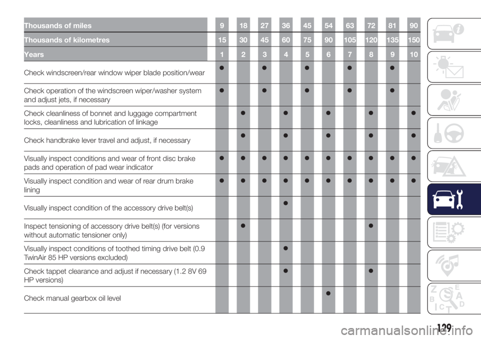
Thousands of miles 9 18 27 36 45 54 63 72 81 90
Thousands of kilometres 15 30 45 60 75 90 105 120 135 150
Years12345678910
Check windscreen/rear window wiper blade position/wear
Check operation of the windscreen wiper/washer system
and adjust jets, if necessary
Check cleanliness of bonnet and luggage compartment
locks, cleanliness and lubrication of linkage
Check handbrake lever travel and adjust, if necessary
Visually inspect conditions and wear of front disc brake
pads and operation of pad wear indicator
Visually inspect condition and wear of rear drum brake
lining
Visually inspect condition of the accessory drive belt(s)
Inspect tensioning of accessory drive belt(s) (for versions
without automatic tensioner only)
Visually inspect conditions of toothed timing drive belt (0.9
TwinAir 85 HP versions excluded)
Check tappet clearance and adjust if necessary (1.2 8V 69
HP versions)
Check manual gearbox oil level
129
Page 136 of 200

Thousands of miles 12 24 36 48 60 72 84 96 108 120
Thousands of kilometres 20 40 60 80 100 120 140 160 180 200
Years12345678910
Check windscreen/rear window wiper blade position/wear
Check operation of the windscreen wiper/washer system
and adjust jets, if necessary
Check cleanliness of bonnet and luggage compartment
locks, cleanliness and lubrication of linkage
Check handbrake lever travel and adjust, if necessary
Visually inspect conditions and wear of front disc brake
pads and operation of pad wear indicator
Visually inspect condition and wear of rear drum brake
lining
Visually inspect condition of the accessory drive belt(s)
Check manual gearbox oil level
134
SERVICING AND CARE