instrument panel Lancia Ypsilon 2020 Owner handbook (in English)
[x] Cancel search | Manufacturer: LANCIA, Model Year: 2020, Model line: Ypsilon, Model: Lancia Ypsilon 2020Pages: 200, PDF Size: 4.53 MB
Page 88 of 200

Main recommendations to carry
children safely
Install the child restraint systems on
the rear seat, which is the most
protected position in the event of an
impact.
Keep children in rearward facing
child restraint systems for as long as
possible, until 3–4 years old if possible.
Should a rearward facing child
restraint system be installed on the rear
seats, it is advisable to position it as
far forward as the position of the front
seat allows.
If the passenger's front airbag is
deactivated always check the
permanent switching-on of the
dedicated warning light on the
instrument panel to make sure that it
has actually been deactivated.
Carefully follow the instructions
supplied with the child restraint system.
Keep the instructions in the vehicle
along with the other documents and
this handbook. Do not use second-
hand child restraint systems without
instructions.
Only one child is to be strapped into
each restraint system; never carry two
children using one child restraint
system.
Always check that the seat belts do
not rest on the child’s neck.
Always check that the seat belt is
well fastened by pulling on it.
While travelling, do not let the child
sit incorrectly or unfasten the belts.
Never allow a child to put the belt's
diagonal section under an arm or
behind their back.
Never carry children on your lap,
even newborns. No one can hold
a child in the case of an accident.
In the event of an accident, replace
the child restraint system with a new
one.
If child seats facing forward are
used, adjust the headrest of the vehicle
seat in the highest setting position.
WARNING
80)SEVERE DANGER When a front
passenger airbag is fitted, do not install
rearward facing child restraint systems on
the front passenger seat. Deployment of
the airbag in an accident could cause fatal
injuries to the child regardless of the
severity of the collision. It is advisable to
always carry children in a child restraint
system on the rear seat, which is the most
protected position in the event of a
collision.81)On the sun visor there is a label with
suitable symbols reminding the user that it
is compulsory to deactivate the airbag if
a rearward facing child restraint system is
fitted. Always comply with the instructions
on the passenger side sun visor (see the
"Supplementary Restraint System (SRS)
- Airbag" paragraph).
82)Should it be absolutely necessary to
carry a child on the front seat in a
backwards-facing craddle seat, the
passenger's front and side airbags must be
deactivated through the Setup menu.
Deactivation should be verified by checking
the
warning light on the instrument
panel. Move the passenger's seat as far
back as possible to avoid contact between
the child seat and the dashboard.
83)Do not move the front or rear seat if a
child is seated on it or on the dedicated
child restraint system.
84)Incorrect fitting of the child restraint
system may result in an inefficient
protection system. In the event of an
accident the child restraint system may
become loose and the child may be
injured, even fatally. When fitting a restraint
system for newborns or children, strictly
comply with the instructions provided
by the Manufacturer.
85)When the child restraint system is not
used, secure it with the seat belt or with
the ISOFIX anchorages, or remove it from
the vehicle. Do not leave it unsecured
inside the passenger compartment. In this
way, in the case of sudden braking or an
accident, it will not cause injuries to the
occupants.
86
SAFETY
Page 90 of 200

Passenger side front airbag
This consists of an instantly inflating
bag contained in a special recess in the
dashboard: this bag has a larger
volume than that on the driver side.fig.
64Passenger side front airbag and
child restraint systems
93)
ALWAYScomply with the instructions
on the label stuck on both sides of
the sun visor (fig. 65).
Deactivating the passenger side
airbags: front airbag and side bag
If a child must be carried on the front
seat in a backwards facing child seat,
deactivate the passenger side front
airbag and front side bag (for
versions/markets, where provided).
With the airbags deactivated, the
warning light switches on in the
instrument panel.
IMPORTANT To manually deactivate the
passenger's front airbag and the front
side bag (for versions/markets, where
provided), operate on the Setup Menu
of the display.
63L0F0402C
64L0F0073C
65F0Y0708C
88
SAFETY
Page 96 of 200
STARTING THE
ENGINE
107) 108)34) 35) 36) 37)
Before starting the engine, adjust the
seat, the interior rear view mirrors,
the door mirrors and fasten the seat
belt correctly.
Never press the accelerator pedal for
starting the engine.
PETROL VERSIONS
Proceed as follows:
engage the handbrake and put the
gear lever in neutral.On 0.9 TwinAir
versionsengage the handbrake and
place the gear lever in neutral or fully
press the clutch pedal if a gear other
than neutral is engaged;
for all versions (except 0.9
TwinAir)fully depress the clutch pedal
without touching the accelerator;
turn the ignition key to AVV and
release it as soon as the engine starts.
DIESEL VERSIONS
Proceed as follows:
engage the handbrake and put the
gear lever in neutral;
turn the ignition key to MAR: the
warning lights
andon the
instrument panel will turn on;
wait for the warning lightsand
to switch off;
fully depress the clutch pedal
without touching the accelerator;
turn the ignition key to the AVV
position as soon as the warning light
turns off. Waiting too long will waste
the heating work carried out by the
plugs. Release the key as soon as the
engine starts.
IMPORTANT With cold engine, the
accelerator must be entirely released
when turning the ignition key to position
AVV. If the engine does not start at the
first attempt, return the ignition key
to STOP before repeating the starting
procedure. If, when the ignition key is at
MAR, the instrument panel warning
light
remains lit, turn the key to
STOP and then back to MAR. If the
warning light remains on, try with the
other keys provided with the car.
Contact a Lancia Dealership if you still
cannot start the engine.VERSIONS WITH DUAL
FUNCTION SYSTEM
TRANSMISSION
109)
The system allows the engine to be
started both with a gear engaged and
with the transmission in neutral (N).
However, the brake pedal must always
be pressed first if neutral is not
engaged. It is therefore advisable to
position the gear lever at N before
starting the engine.
LPG AND NATURAL
POWER VERSIONS
38)
The engine always starts up on petrol
independently of the previously
selected mode.
SWITCHING OFF THE
ENGINE
39)
Turn the ignition key to STOP while the
engine is idling.
IMPORTANT After a demanding drive,
before turning the engine off you should
allow it to idle to allow the temperature
in the engine compartment to
decrease.
94
STARTING AND DRIVING
Page 97 of 200
WARNING
107)It is dangerous to run the engine in
enclosed areas. The engine consumes
oxygen and engine exhaust contains
carbon dioxide, carbon monoxide and
other toxic gasses.
108)Remember that the brake servo and
power steering are not operational until the
engine has been started, therefore much
effort than usual is required on the brake
pedal and steering wheel.
109)If the engine fails to start with a gear
engaged, the potentially dangerous
situation due to the fact that the gearbox is
automatically placed in neutral will be
signalled by a buzzer.
WARNING
34)The flashing of the warning lightfor
60 seconds after starting or during
prolonged cranking of the engine indicates
a fault with the glow plug heating system.
You can use the car as usual if the engine
starts but you should contact a Lancia
Dealership as soon as possible.
35)It is advisable not to demand maximum
performance from your car (e.g. excessive
acceleration, long distances at maximum
rpm, excessively intense braking, etc.)
when it is first used.
36)When the engine is switched off never
leave the key turned to MAR-ON to prevent
useless current absorption from draining
the battery.37)Never, under any circumstances, jump
start the engine by pushing, towing or
coasting downhill. This could cause fuel to
flow into the catalytic converter and
damage it beyond repair.
38)There must therefore always be
enough petrol in the tank to protect the
petrol pump and to guarantee temporary
switching from methane to petrol
operation, if high performance is required.
39)A quick burst on the accelerator before
turning off the engine serves absolutely
no practical purpose, it wastes fuel and is
especially damaging to turbocharged
engines.
HANDBRAKE
110) 111) 112)
The handbrake lever is located between
the two front seats.
Handbrake engagement: pull lever A
fig. 69 upwards until the vehicle is
braked.
Handbrake disengagement: slightly
raise lever A and press the release
button B fig. 69 checking that the
warning light
switches off in the
instrument panel.
69L0F0074C
95
Page 99 of 200
DUAL FUNCTION
SYSTEM GEARBOX
(for versions/markets, where provided)
The car may be equipped with an
electronically controlled manual
transmission known as "Dual FuNction
System" which allows two operating
logics: MANUAL and AUTO.
GEAR LEVER
41)
The lever fig. 71 is "multistable" floating
type, in other words it has three stable
and three unstable positions.
The three stable positions correspond
to neutral (N), reverse (R) and the
central position located between the
unstable positions (+) and (-).The unstable positions, in other words
those that are abandoned as soon
as the lever is released, are the position
which requests a higher gear (+), the
position which requests a lower gear (–)
and the automatic/manual operating
mode request position (A/M).
IMPORTANT With the engine started,
any error between the lever position
and the gear actually engaged is
signalled by a buzzer until consistency
is restored.
MANUAL MODE
Press the brake pedal and start the
engine;
if AUTO appears on the display,
move the gear lever fig. 71 to A/M to
select MANUAL mode;
push the gear lever towards (+) to
engage first gear (if starting from N
or R, simply place the lever in the
middle position) or R to engage reverse;
release the brake pedal and press
the accelerator pedal;
in driving conditions, push the gear
lever towards (+) to engage the next
gear up or towards (–) to engage the
next gear down.AUTOMATIC MODE
Press the brake pedal and start the
engine;
if AUTO is not on the display, move
the shift lever fig. 71 to A/M to select
AUTOMATIC mode;
push the gear lever towards (+) to
engage 1stgear (if starting from N or R,
simply place the lever in the middle
position) or R to engage reverse;
release the brake pedal and press
the accelerator pedal: the gear most
suited to the vehicle speed will be
engaged.
OPERATION (AUTO-ECO)
The ECO function, which optimises the
gearbox, can be activated only with
automatic mode on. The ECO function
is activated by pressing the ECO button
on the instrument panel.
“Kick Down” FUNCTION
If necessary (e.g. when overtaking), the
system downshifts one or more gears
when the accelerator pedal is
depressed beyond the point where it
becomes stiff (and if the rpm allow it) in
order to provide suitable power and
torque for the acceleration requested
by the driver.
71L0F0117C
97
Page 109 of 200
HAZARD WARNING
LIGHTS
Press button A fig. 82 to switch the
lights on/off. When the hazard warning
lights are on, the
andwarning
lights flash.
IMPORTANT The use of hazard warning
lights is governed by the highway
code of the country you are driving in:
comply with legal requirements.
Emergency braking
In the event of emergency braking the
hazard warning lights switch on
automatically as well as the
and
warning lights in the instrument
panel.
The lights switch off automatically when
emergency braking ceases.
REPLACING A BULB
GENERAL
INSTRUCTIONS
121) 122)51) 52)
Before replacing a bulb check the
contacts for oxidation;
burnt bulbs must be replaced by
others of the same type and power;
after replacing a headlight bulb,
always check its alignment;
when a light is not working, check
that the corresponding fuse is intact
before replacing a bulb. For the location
of fuses, refer to the paragraph
"Replacing fuses" in this chapter.
IMPORTANT When the weather is cold
or damp or after heavy rain or washing,
the surface of headlights or rear lights
may steam up and/or form drops of
condensation on the inside. This is
a natural phenomenon due to the
difference in temperature and humidity
between the inside and the outside
of the glass which does not indicate a
fault and does not compromise the
normal operation of lighting devices.
The mist disappears quickly when the
lights are turned on, starting from
the centre of the diffuser, extending
progressively towards the edges.
82L0F0429C
107
Page 117 of 200
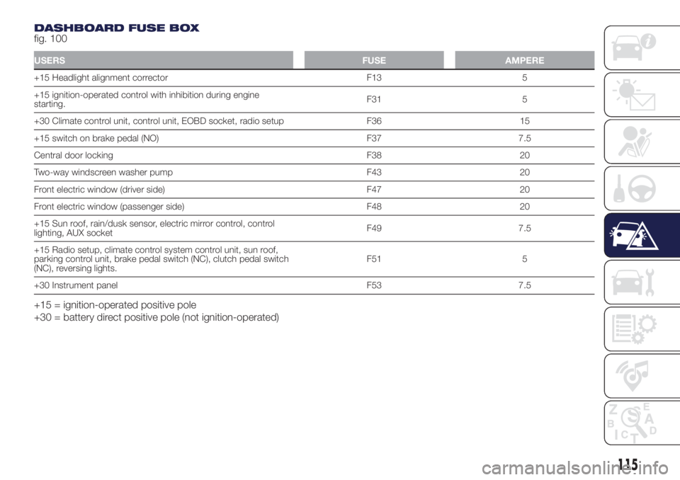
DASHBOARD FUSE BOX
fig. 100
USERSFUSE AMPERE
+15 Headlight alignment corrector F13 5
+15 ignition-operated control with inhibition during engine
starting.F31 5
+30 Climate control unit, control unit, EOBD socket, radio setup F36 15
+15 switch on brake pedal (NO) F37 7.5
Central door locking F38 20
Two-way windscreen washer pump F43 20
Front electric window (driver side) F47 20
Front electric window (passenger side) F48 20
+15 Sun roof, rain/dusk sensor, electric mirror control, control
lighting, AUX socketF49 7.5
+15 Radio setup, climate control system control unit, sun roof,
parking control unit, brake pedal switch (NC), clutch pedal switch
(NC), reversing lights.F51 5
+30 Instrument panel F53 7.5
+15 = ignition-operated positive pole
+30 = battery direct positive pole (not ignition-operated)
115
Page 122 of 200
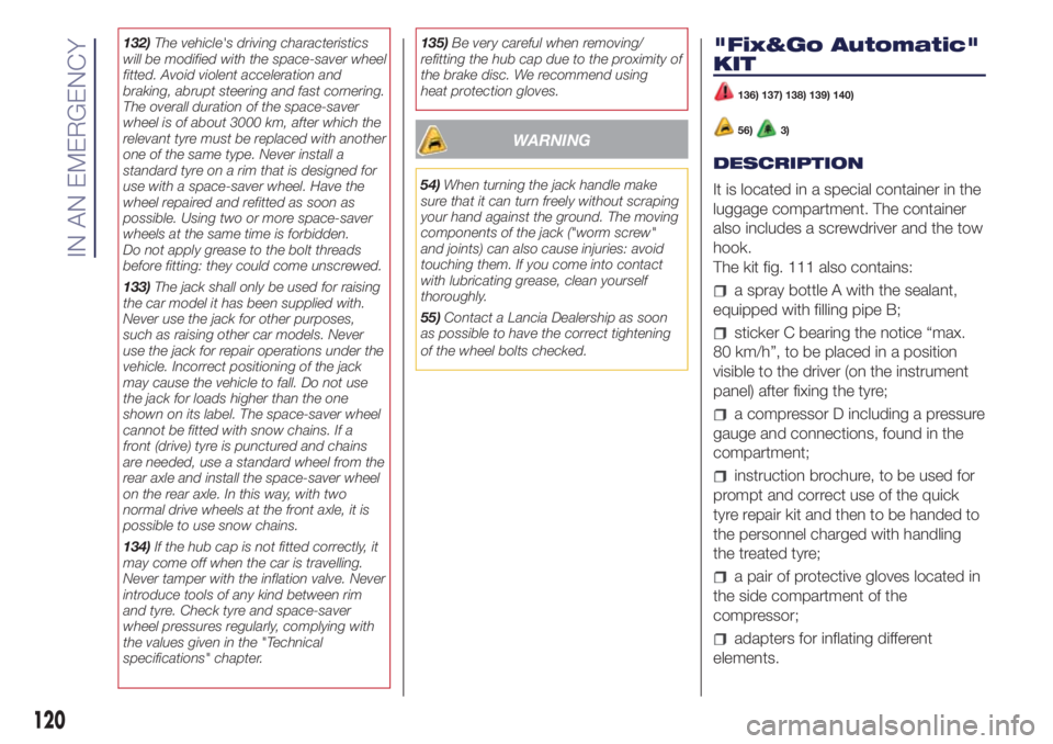
132)The vehicle's driving characteristics
will be modified with the space-saver wheel
fitted. Avoid violent acceleration and
braking, abrupt steering and fast cornering.
The overall duration of the space-saver
wheel is of about 3000 km, after which the
relevant tyre must be replaced with another
one of the same type. Never install a
standard tyre on a rim that is designed for
use with a space-saver wheel. Have the
wheel repaired and refitted as soon as
possible. Using two or more space-saver
wheels at the same time is forbidden.
Do not apply grease to the bolt threads
before fitting: they could come unscrewed.
133)The jack shall only be used for raising
the car model it has been supplied with.
Never use the jack for other purposes,
such as raising other car models. Never
use the jack for repair operations under the
vehicle. Incorrect positioning of the jack
may cause the vehicle to fall. Do not use
the jack for loads higher than the one
shown on its label. The space-saver wheel
cannot be fitted with snow chains. If a
front (drive) tyre is punctured and chains
are needed, use a standard wheel from the
rear axle and install the space-saver wheel
on the rear axle. In this way, with two
normal drive wheels at the front axle, it is
possible to use snow chains.
134)If the hub cap is not fitted correctly, it
may come off when the car is travelling.
Never tamper with the inflation valve. Never
introduce tools of any kind between rim
and tyre. Check tyre and space-saver
wheel pressures regularly, complying with
the values given in the "Technical
specifications" chapter.135)Be very careful when removing/
refitting the hub cap due to the proximity of
the brake disc. We recommend using
heat protection gloves.
WARNING
54)When turning the jack handle make
sure that it can turn freely without scraping
your hand against the ground. The moving
components of the jack ("worm screw"
and joints) can also cause injuries: avoid
touching them. If you come into contact
with lubricating grease, clean yourself
thoroughly.
55)Contact a Lancia Dealership as soon
as possible to have the correct tightening
of the wheel bolts checked.
"Fix&Go Automatic"
KIT
136) 137) 138) 139) 140)
56)3)
DESCRIPTION
It is located in a special container in the
luggage compartment. The container
also includes a screwdriver and the tow
hook.
The kit fig. 111 also contains:
a spray bottle A with the sealant,
equipped with filling pipe B;
sticker C bearing the notice “max.
80 km/h”, to be placed in a position
visible to the driver (on the instrument
panel) after fixing the tyre;
a compressor D including a pressure
gauge and connections, found in the
compartment;
instruction brochure, to be used for
prompt and correct use of the quick
tyre repair kit and then to be handed to
the personnel charged with handling
the treated tyre;
a pair of protective gloves located in
the side compartment of the
compressor;
adapters for inflating different
elements.
120
IN AN EMERGENCY
Page 130 of 200
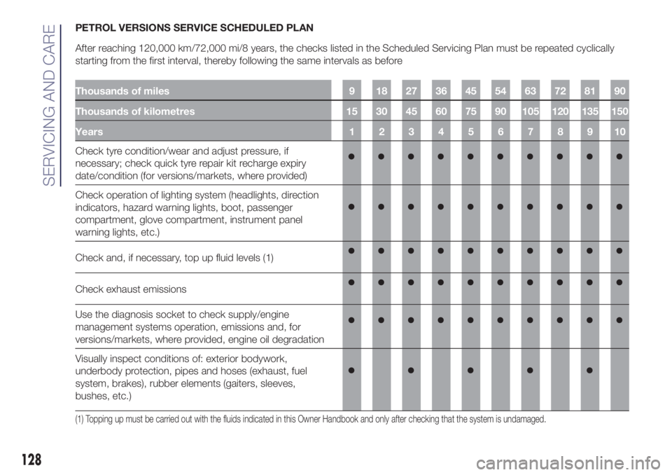
PETROL VERSIONS SERVICE SCHEDULED PLAN
After reaching 120,000 km/72,000 mi/8 years, the checks listed in the Scheduled Servicing Plan must be repeated cyclically
starting from the first interval, thereby following the same intervals as before
Thousands of miles 9 18 27 36 45 54 63 72 81 90
Thousands of kilometres 15 30 45 60 75 90 105 120 135 150
Years12345678910
Check tyre condition/wear and adjust pressure, if
necessary; check quick tyre repair kit recharge expiry
date/condition (for versions/markets, where provided)
Check operation of lighting system (headlights, direction
indicators, hazard warning lights, boot, passenger
compartment, glove compartment, instrument panel
warning lights, etc.)
Check and, if necessary, top up fluid levels (1)
Check exhaust emissions
Use the diagnosis socket to check supply/engine
management systems operation, emissions and, for
versions/markets, where provided, engine oil degradation
Visually inspect conditions of: exterior bodywork,
underbody protection, pipes and hoses (exhaust, fuel
system, brakes), rubber elements (gaiters, sleeves,
bushes, etc.)
(1) Topping up must be carried out with the fluids indicated in this Owner Handbook and only after checking that the system is undamaged.
128
SERVICING AND CARE
Page 135 of 200
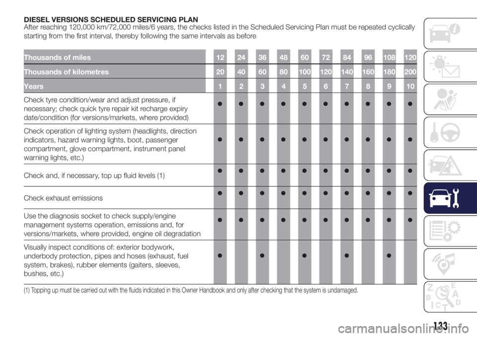
DIESEL VERSIONS SCHEDULED SERVICING PLAN
After reaching 120,000 km/72,000 miles/6 years, the checks listed in the Scheduled Servicing Plan must be repeated cyclically
starting from the first interval, thereby following the same intervals as before
Thousands of miles 12 24 36 48 60 72 84 96 108 120
Thousands of kilometres 20 40 60 80 100 120 140 160 180 200
Years12345678910
Check tyre condition/wear and adjust pressure, if
necessary; check quick tyre repair kit recharge expiry
date/condition (for versions/markets, where provided)
Check operation of lighting system (headlights, direction
indicators, hazard warning lights, boot, passenger
compartment, glove compartment, instrument panel
warning lights, etc.)
Check and, if necessary, top up fluid levels (1)
Check exhaust emissions
Use the diagnosis socket to check supply/engine
management systems operation, emissions and, for
versions/markets, where provided, engine oil degradation
Visually inspect conditions of: exterior bodywork,
underbody protection, pipes and hoses (exhaust, fuel
system, brakes), rubber elements (gaiters, sleeves,
bushes, etc.)
(1) Topping up must be carried out with the fluids indicated in this Owner Handbook and only after checking that the system is undamaged.
133