instrument panel Lancia Ypsilon 2020 Owner handbook (in English)
[x] Cancel search | Manufacturer: LANCIA, Model Year: 2020, Model line: Ypsilon, Model: Lancia Ypsilon 2020Pages: 200, PDF Size: 4.53 MB
Page 7 of 200
KNOWING YOUR CAR
KNOWING THE INSTRUMENT PANEL
SAFETY
STARTING AND DRIVING
IN AN EMERGENCY
SERVICING AND CARE
TECHNICAL DATA
MULTIMEDIA
INDEX
5
Page 9 of 200
KNOWING YOUR CAR
In-depth knowledge of your new vehicle
starts here.
The booklet that you are reading simply
and directly explains how it is made
and how it works.
That’s why we advise you to read it
seated comfortably on board, so that
you can see immediately what is
described here for yourself.INSTRUMENT PANEL ..................... 8
THE KEYS ...................................... 9
IGNITION DEVICE ........................... 10
THE LANCIA CODE SYSTEM.......... 11
DOORS ........................................... 11
SEATS ............................................ 13
HEADRESTS ................................... 15
STEERING WHEEL ......................... 16
REAR VIEW MIRRORS .................... 16
EXTERIOR LIGHTS ......................... 17
INTERIOR LIGHTS .......................... 20
WINDSCREEN / REAR WINDOW
WIPERS .......................................... 21
CLIMATE CONTROL ....................... 23
ELECTRIC WINDOWS .................... 27
ELECTRIC SUN ROOF .................... 28
CONTROLS .................................... 29
BONNET ......................................... 30
BOOT ............................................. 32
VERSION WITH LPG SYSTEM ........ 33
VERSION WITH METHANE
SYSTEM (NATURAL POWER) ......... 35
7
Page 10 of 200
INSTRUMENT PANEL
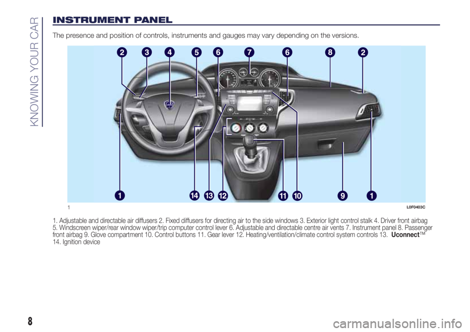
The presence and position of controls, instruments and gauges may vary depending on the versions.
1. Adjustable and directable air diffusers 2. Fixed diffusers for directing air to the side windows 3. Exterior light control stalk 4. Driver front airbag
5. Windscreen wiper/rear window wiper/trip computer control lever 6. Adjustable and directable centre air vents 7. Instrument panel 8. Passenger
front airbag 9. Glove compartment 10. Control buttons 11. Gear lever 12. Heating/ventilation/climate control system controls 13.Uconnect™
14. Ignition device
1L0F0403C
8
KNOWING YOUR CAR
Page 13 of 200
THE LANCIA CODE
SYSTEM
This is an electronic engine locking
system which increases protection
against attempted thefts of the vehicle.
It is automatically activated when the
ignition key is removed.
Each key contains an electronic device
which modulates the signal emitted
during ignition by an antenna built into
the ignition device. The signal is the
"password", different every time the
vehicle is started, through which the
control unit recognises the key and
enables starting.
OPERATION
Each time the car is started by turning
the ignition key to MAR, the Lancia
CODE system control unit sends an
acknowledgement code to the
Powertrain Control Module to
deactivate the immobiliser. The code is
sent only if the control unit of the Lancia
CODE system has acknowledged the
code received from the key.Each time the ignition key is turned to
STOP, the Lancia CODE system
deactivates the functions of the
management engine control unit. If,
during starting, the code is not correctly
recognised, the
warning light
switches on in the instrument panel. In
this case, turn the key to STOP and
then to MAR-ON; if it is still locked, try
again with the other keys that come
with the car. Contact a Lancia
Dealership if you still cannot start the
engine.
If the
warning light switches on, this
means that the system is running a
self-diagnosis (for example due to
a voltage drop). If the problem persists,
contact a Lancia Dealership.
DOORS
LOCKING/UNLOCKING
DOORS FROM THE
INSIDE
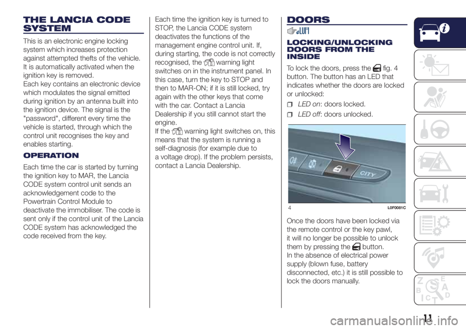
To lock the doors, press the
fig. 4
button. The button has an LED that
indicates whether the doors are locked
or unlocked:
LED on: doors locked.
LED off: doors unlocked.
Once the doors have been locked via
the remote control or the key pawl,
it will no longer be possible to unlock
them by pressing the
button.
In the absence of electrical power
supply (blown fuse, battery
disconnected, etc.) it is still possible to
lock the doors manually.
4L0F0081C
11
Page 19 of 200
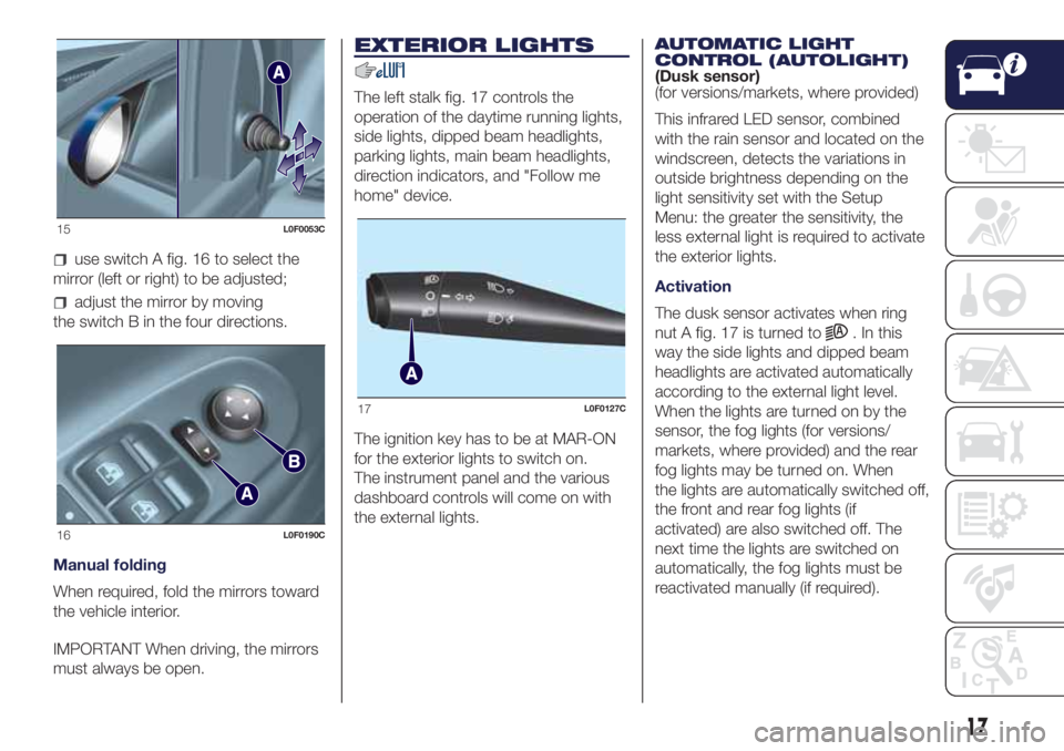
use switch A fig. 16 to select the
mirror (left or right) to be adjusted;
adjust the mirror by moving
the switch B in the four directions.
Manual folding
When required, fold the mirrors toward
the vehicle interior.
IMPORTANT When driving, the mirrors
must always be open.
EXTERIOR LIGHTS
The left stalk fig. 17 controls the
operation of the daytime running lights,
side lights, dipped beam headlights,
parking lights, main beam headlights,
direction indicators, and "Follow me
home" device.
The ignition key has to be at MAR-ON
for the exterior lights to switch on.
The instrument panel and the various
dashboard controls will come on with
the external lights.AUTOMATIC LIGHT
CONTROL (AUTOLIGHT)
(Dusk sensor)
(for versions/markets, where provided)
This infrared LED sensor, combined
with the rain sensor and located on the
windscreen, detects the variations in
outside brightness depending on the
light sensitivity set with the Setup
Menu: the greater the sensitivity, the
less external light is required to activate
the exterior lights.
Activation
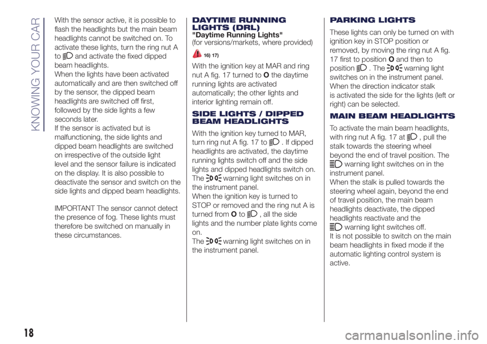
The dusk sensor activates when ring
nut A fig. 17 is turned to
. In this
way the side lights and dipped beam
headlights are activated automatically
according to the external light level.
When the lights are turned on by the
sensor, the fog lights (for versions/
markets, where provided) and the rear
fog lights may be turned on. When
the lights are automatically switched off,
the front and rear fog lights (if
activated) are also switched off. The
next time the lights are switched on
automatically, the fog lights must be
reactivated manually (if required).
15L0F0053C
16L0F0190C
17L0F0127C
17
Page 20 of 200
With the sensor active, it is possible to
flash the headlights but the main beam
headlights cannot be switched on. To
activate these lights, turn the ring nut A
to
and activate the fixed dipped
beam headlights.
When the lights have been activated
automatically and are then switched off
by the sensor, the dipped beam
headlights are switched off first,
followed by the side lights a few
seconds later.
If the sensor is activated but is
malfunctioning, the side lights and
dipped beam headlights are switched
on irrespective of the outside light
level and the sensor failure is indicated
on the display. It is also possible to
deactivate the sensor and switch on the
side lights and dipped beam headlights.
IMPORTANT The sensor cannot detect
the presence of fog. These lights must
therefore be switched on manually in
these circumstances.DAYTIME RUNNING
LIGHTS (DRL)
"Daytime Running Lights"
(for versions/markets, where provided)16) 17)
With the ignition key at MAR and ring
nut A fig. 17 turned toOthe daytime
running lights are activated
automatically; the other lights and
interior lighting remain off.
SIDE LIGHTS / DIPPED
BEAM HEADLIGHTS
With the ignition key turned to MAR,
turn ring nut A fig. 17 to
. If dipped
headlights are activated, the daytime
running lights switch off and the side
lights and dipped headlights switch on.
The
warning light switches on in
the instrument panel.
When the ignition key is turned to
STOP or removed and the ring nut A is
turned fromOto
, all the side
lights and the number plate lights come
on.
The
warning light switches on in
the instrument panel.PARKING LIGHTS
These lights can only be turned on with
ignition key in STOP position or
removed, by moving the ring nut A fig.
17 first to positionOand then to
position
. Thewarning light
switches on in the instrument panel.
When the direction indicator stalk
is activated the side for the lights (left or
right) can be selected.
MAIN BEAM HEADLIGHTS
To activate the main beam headlights,
with ring nut A fig. 17 at
, pull the
stalk towards the steering wheel
beyond the end of travel position. The
warning light switches on in the
instrument panel.
When the stalk is pulled towards the
steering wheel again, beyond the end
of travel position, the main beam
headlights deactivate, the dipped
headlights reactivate and the
warning light switches off.
It is not possible to switch on the main
beam headlights in fixed mode if the
automatic lighting control system is
active.
18
KNOWING YOUR CAR
Page 21 of 200
FLASHING
To do this, pull the stalk fig. 17 towards
the steering wheel (unstable position)
regardless of the position of ring nut A.
The
warning light switches on in
the instrument panel.
DIRECTION INDICATORS
Bring the stalk fig. 17 to the (stable)
position:
upwards:activates the right direction
indicator;
downwards:activates the left direction
indicator.
Warning light
orwill blink on the
instrument panel.
The direction indicators switch off
automatically when the steering wheel
is straightened.
"Lane Change" function
If you wish to signal a lane change,
place the left stalk in the unstable
position for less than half a second.
The direction indicator on the side
selected will flash five times and then
switch off automatically."FOLLOW ME HOME"
DEVICE
This allows the space in front of the
vehicle to be lit for a set time.
Activation
The "Follow Me Home" device is
activated by pulling the stalk fig. 17
towards the steering wheel, in addition
to the stroke end click.
It is possible to enable this function
within 2 minutes after turning off the
engine. This function allows turning on
lights and low beams.
It is possible to set the headlights
turning on time by pulling the left lever
towards the steering wheel (unstable
position) one or more times. In this case
it is possible to choose between 0, 30,
60, 90 up to a maximum of 210
seconds.
Each time the stalk is operated, the
warning light
on the instrument
panel switches on. The display shows a
message and the time set for the
function. The
warning light comes
on when the stalk is first moved and
stays on until the function is
automatically deactivated.Off
This function is deactivated turning on
again the headlights, sidelights or
pulling the left lever towards the
steering wheel (unstable position) for
more than 2 seconds, or switching the
starter to MAR.
"Follow me home" function with
Uconnect™ system interaction
IfUconnect™ is installed, the function
management remains the same, but
it takes place through interaction with
theUconnect™ menu.
FOG LIGHTS / REAR FOG
LIGHTS
(for versions/markets, where provided)
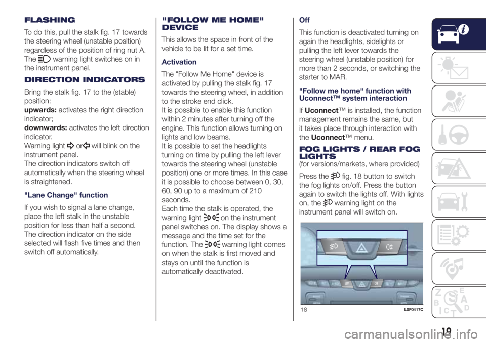
Press the
fig. 18 button to switch
the fog lights on/off. Press the button
again to switch the lights off. With lights
on, the
warning light on the
instrument panel will switch on.
18L0F0417C
19
Page 23 of 200
WINDSCREEN /
REAR WINDOW
WIPERS
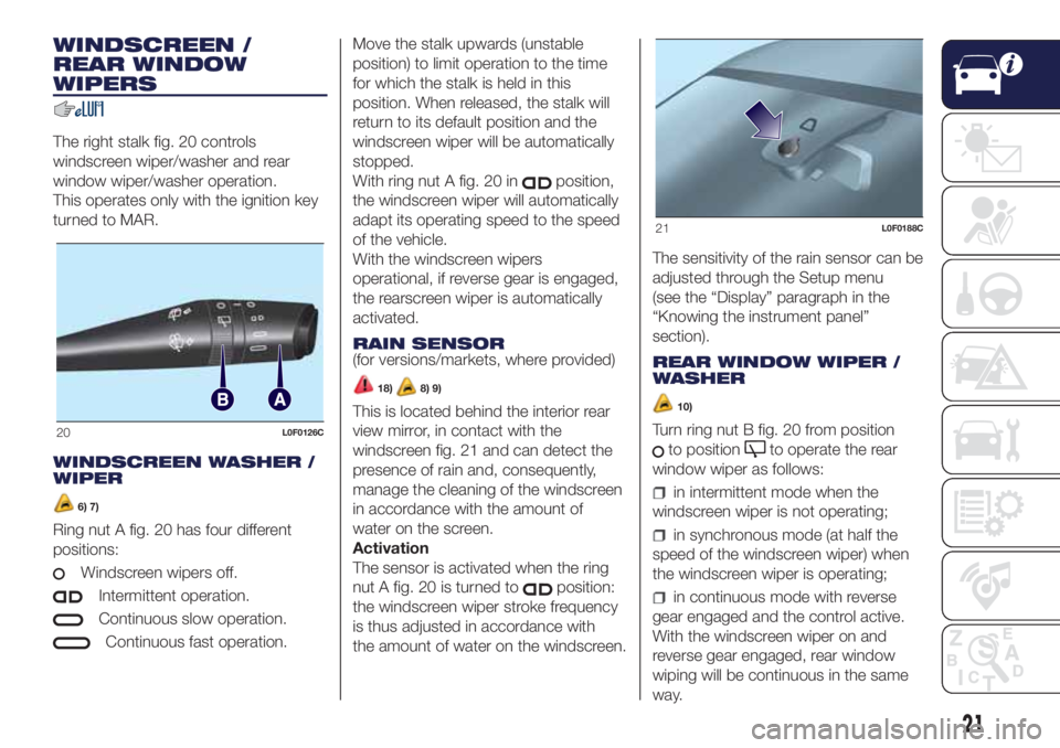
The right stalk fig. 20 controls
windscreen wiper/washer and rear
window wiper/washer operation.
This operates only with the ignition key
turned to MAR.
WINDSCREEN WASHER /
WIPER
6) 7)
Ring nut A fig. 20 has four different
positions:
Windscreen wipers off.
Intermittent operation.
Continuous slow operation.
Continuous fast operation.Move the stalk upwards (unstable
position) to limit operation to the time
for which the stalk is held in this
position. When released, the stalk will
return to its default position and the
windscreen wiper will be automatically
stopped.
With ring nut A fig. 20 in
position,
the windscreen wiper will automatically
adapt its operating speed to the speed
of the vehicle.
With the windscreen wipers
operational, if reverse gear is engaged,
the rearscreen wiper is automatically
activated.
RAIN SENSOR
(for versions/markets, where provided)
18)8) 9)
This is located behind the interior rear
view mirror, in contact with the
windscreen fig. 21 and can detect the
presence of rain and, consequently,
manage the cleaning of the windscreen
in accordance with the amount of
water on the screen.
Activation
The sensor is activated when the ring
nut A fig. 20 is turned to
position:
the windscreen wiper stroke frequency
is thus adjusted in accordance with
the amount of water on the windscreen.The sensitivity of the rain sensor can be
adjusted through the Setup menu
(see the “Display” paragraph in the
“Knowing the instrument panel”
section).
REAR WINDOW WIPER /
WASHER
10)
Turn ring nut B fig. 20 from position
to positionto operate the rear
window wiper as follows:
in intermittent mode when the
windscreen wiper is not operating;
in synchronous mode (at half the
speed of the windscreen wiper) when
the windscreen wiper is operating;
in continuous mode with reverse
gear engaged and the control active.
With the windscreen wiper on and
reverse gear engaged, rear window
wiping will be continuous in the same
way.
20L0F0126C
21L0F0188C
21
Page 31 of 200
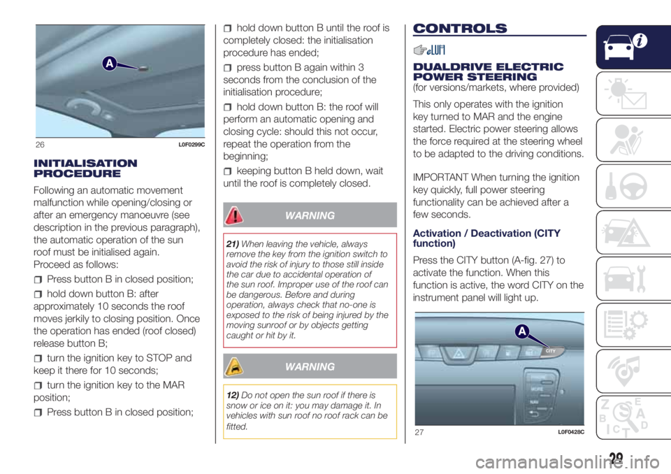
INITIALISATION
PROCEDURE
Following an automatic movement
malfunction while opening/closing or
after an emergency manoeuvre (see
description in the previous paragraph),
the automatic operation of the sun
roof must be initialised again.
Proceed as follows:
Press button B in closed position;
hold down button B: after
approximately 10 seconds the roof
moves jerkily to closing position. Once
the operation has ended (roof closed)
release button B;
turn the ignition key to STOP and
keep it there for 10 seconds;
turn the ignition key to the MAR
position;
Press button B in closed position;
hold down button B until the roof is
completely closed: the initialisation
procedure has ended;
press button B again within 3
seconds from the conclusion of the
initialisation procedure;
hold down button B: the roof will
perform an automatic opening and
closing cycle: should this not occur,
repeat the operation from the
beginning;
keeping button B held down, wait
until the roof is completely closed.
WARNING
21)When leaving the vehicle, always
remove the key from the ignition switch to
avoid the risk of injury to those still inside
the car due to accidental operation of
the sun roof. Improper use of the roof can
be dangerous. Before and during
operation, always check that no-one is
exposed to the risk of being injured by the
moving sunroof or by objects getting
caught or hit by it.
WARNING
12)Do not open the sun roof if there is
snow or ice on it: you may damage it. In
vehicles with sun roof no roof rack can be
fitted.
CONTROLS
DUALDRIVE ELECTRIC
POWER STEERING
(for versions/markets, where provided)
This only operates with the ignition
key turned to MAR and the engine
started. Electric power steering allows
the force required at the steering wheel
to be adapted to the driving conditions.
IMPORTANT When turning the ignition
key quickly, full power steering
functionality can be achieved after a
few seconds.
Activation / Deactivation (CITY
function)
Press the CITY button (A-fig. 27) to
activate the function. When this
function is active, the word CITY on the
instrument panel will light up.
26L0F0299C
27L0F0428C
29
Page 37 of 200
WARNING
14)The car is equipped with a gaseous
LPG injection system designed specifically
for it: it is therefore absolutely forbidden
to alter the configuration of the system or
its components. The use of other
components or materials could cause
malfunctions and lead to a reduction
in safety. If you experience problems, go to
a Lancia Dealership. When towing or
lifting the vehicle, follow the instructions in
the main handbook under the paragraph
on "Towing the vehicle" to prevent damage
to the gas system parts.
15)When using a painting oven, the LPG
tank should be removed from the car
and later carefully refitted at a Lancia
Dealership. Although the LPG system has
numerous safety features, it is advisable
to proceed as follows every time the
vehicle is not in use for a long period or
moved in an emergency as a result of
a breakdown or accident: unscrew the
fastening devices A fig. 35, then remove
the cover B. Close the LPG cock rotating
the ring nut C fig. 36 clockwise. Refit
the cover and retighten the fastening
devices.
16)Periodically (at least once every six
months) it is advisable to let the LPG in the
tank run out and, at the first refuelling, to
check that it does not exceed the
maximum capacity of 30.5 litres (reserve
included) (with a tolerance of 2 litres
excess). If the level is above 30.5 litres
(reserve included) contact a Lancia
Dealership immediately.17)The system operates at temperatures
ranging between -20°C and 100°C.
18)If, during LPG operation, LPG runs out,
the system automatically switches to
petrol operation as indicated by thewarning light on the display.
19)Regardless of the last fuel system
used, at the following engine starting, after
the initial petrol stage, the system will
automatically switch to LPG.
20)When switching is requested, metallic
noise from the valves which pressurise
the circuit can be heard. For the switching
logic described above, a delay between the
valve ticking and the switching off of the
instrument panel indication is completely
normal.
21)In particular usage conditions, such as
starting and operation at low ambient
temperature or LPG supply with low
propane content, the system may switch
temporarily to petrol operation, without
a visual indication of switching on the
instrument panel. In the event of low LPG
levels in the tank or request for high
performance (e.g. overtaking, car fully
laden, steep hills) the system may
automatically switch to petrol operation to
guarantee the engine power requested; the
icon
on the display switches on to
indicate this. When the above conditions
are no longer present, the system
automatically restores LPG operation and
the
icon switches off. To achieve the
automatic switching described above,
make sure that there is always enough fuel
in the petrol tank.
22)It is strictly forbidden to use any
additive in the LPG.
VERSION WITH
METHANE SYSTEM
(Natural Power)
31) 32)
INTRODUCTION
The "Natural Power" version features
two fuel systems, one for petrol and
one for natural gas (methane).
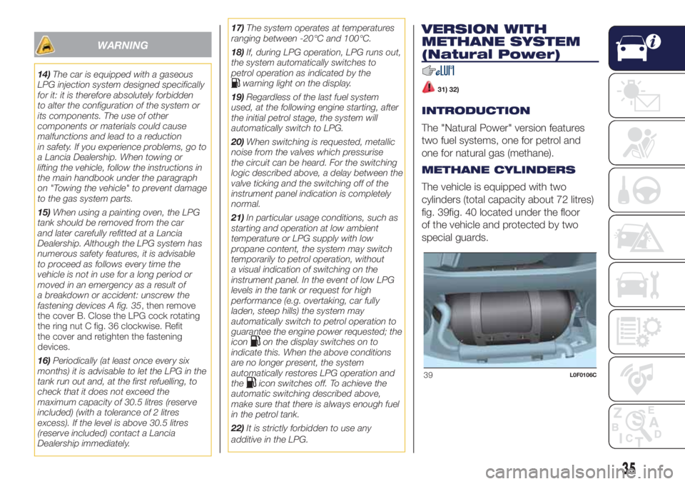
METHANE CYLINDERS
The vehicle is equipped with two
cylinders (total capacity about 72 litres)
fig. 39fig. 40 located under the floor
of the vehicle and protected by two
special guards.
39L0F0106C
35