ignition LAND ROVER DISCOVERY 1999 Owners Manual
[x] Cancel search | Manufacturer: LAND ROVER, Model Year: 1999, Model line: DISCOVERY, Model: LAND ROVER DISCOVERY 1999Pages: 1529, PDF Size: 34.8 MB
Page 856 of 1529

BRAKES
DESCRIPTION AND OPERATION 70-3
1ABS sensor
2ABS modulator
3Return pump relay
4SLABS ECU
5Brake lamp relay
6Centre high mounted stop lamp
7LH brake lamp
8RH brake lamp
9Instrument pack10Body control unit
11Reverse lamp switch (manual gearbox)
12Diagnostic socket
13HDC switch
14Transmission high/low switch
15Centre differential lock switch
16Engine control module
17Battery power supply
18Ignition power supply
Page 870 of 1529

BRAKES
DESCRIPTION AND OPERATION 70-17
SLABS ECU
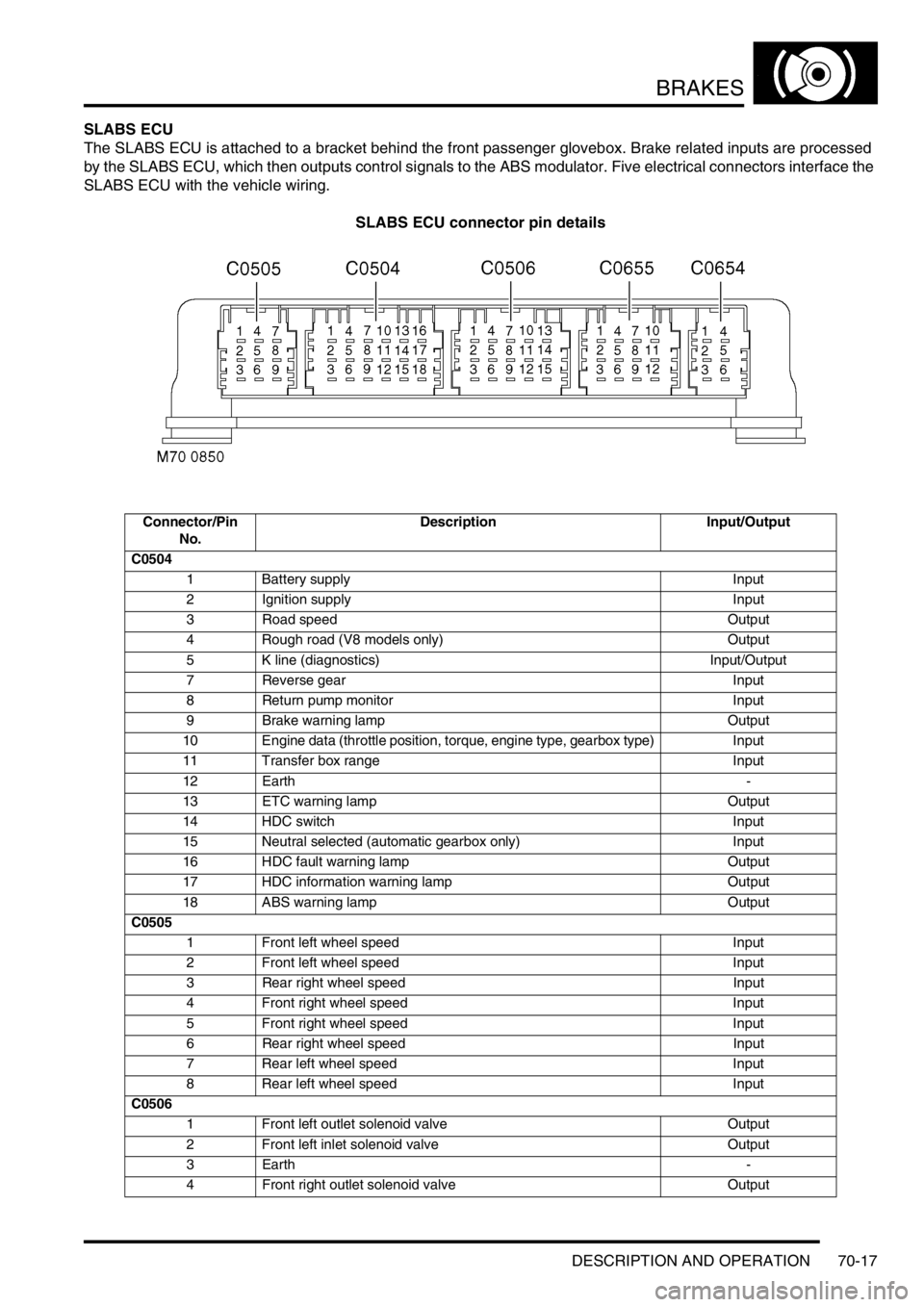
The SLABS ECU is attached to a bracket behind the front passenger glovebox. Brake related inputs are processed
by the SLABS ECU, which then outputs control signals to the ABS modulator. Five electrical connectors interface the
SLABS ECU with the vehicle wiring.
SLABS ECU connector pin details
Connector/Pin
No.Description Input/Output
C0504
1 Battery supply Input
2 Ignition supply Input
3 Road speed Output
4 Rough road (V8 models only) Output
5 K line (diagnostics) Input/Output
7 Reverse gear Input
8 Return pump monitor Input
9 Brake warning lamp Output
10 Engine data (throttle position, torque, engine type, gearbox type) Input
11 Transfer box range Input
12 Earth-
13 ETC warning lamp Output
14 HDC switch Input
15 Neutral selected (automatic gearbox only) Input
16 HDC fault warning lamp Output
17 HDC information warning lamp Output
18 ABS warning lamp Output
C0505
1 Front left wheel speed Input
2 Front left wheel speed Input
3 Rear right wheel speed Input
4 Front right wheel speed Input
5 Front right wheel speed Input
6 Rear right wheel speed Input
7 Rear left wheel speed Input
8 Rear left wheel speed Input
C0506
1 Front left outlet solenoid valve Output
2 Front left inlet solenoid valve Output
3Earth-
4 Front right outlet solenoid valve Output
Page 872 of 1529

BRAKES
DESCRIPTION AND OPERATION 70-19
ABS sensors
The ABS sensors supply the SLABS ECU with a sinusoidal speed signal from each wheel. An inductive sensor,
installed in the hub bearing of each wheel, senses off a 60 tooth exciter ring integrated into the inner race of the hub
bearing. Each ABS sensor has a fly-lead connecting it to the vehicle wiring.
HDC switch
The HDC switch is a latching push switch installed on the fascia, in the switchpack inboard of the steering wheel.
When pushed in, the switch connects an ignition supply to the SLABS ECU to initiate HDC.
Warning indications
The SLABS ECU operates audible and visual warnings to convey brake system status.
Audible warning
A repetitive chime, at a frequency of 2 Hz, draws attention to warning lamp indications. The chime is produced on the
speaker in the instrument pack.
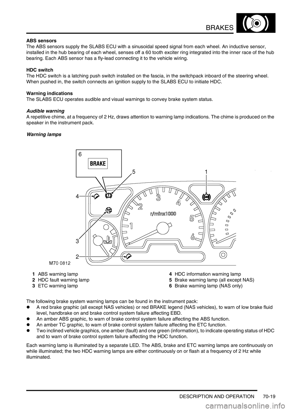
Warning lamps
1ABS warning lamp
2HDC fault warning lamp
3ETC warning lamp4HDC information warning lamp
5Brake warning lamp (all except NAS)
6Brake warning lamp (NAS only)
The following brake system warning lamps can be found in the instrument pack:
lA red brake graphic (all except NAS vehicles) or red BRAKE legend (NAS vehicles), to warn of low brake fluid
level, handbrake on and brake control system failure affecting EBD.
lAn amber ABS graphic, to warn of brake control system failure affecting the ABS function.
lAn amber TC graphic, to warn of brake control system failure affecting the ETC function.
lTwo inclined vehicle graphics, one amber (fault) and one green (information), to indicate operating status of HDC
and to warn of brake control system failure affecting the HDC function.
Each warning lamp is illuminated by a separate LED. The ABS, brake and ETC warning lamps are continuously on
while illuminated; the two HDC warning lamps are either continuously on or flash at a frequency of 2 Hz while
illuminated.
Page 873 of 1529

BRAKES
70-20 DESCRIPTION AND OPERATION
Operation
Refer to illustration.
+ BRAKES, DESCRIPTION AND OPERATION, Brake system control diagram.
When the ignition is switched on, the SLABS ECU performs a check of the brake related warning lamps as part of the
power up procedure. The warning lamps are illuminated for approximately 3 seconds and then extinguished. If a fault
warning lamp remains illuminated after the lamp check, a fault has been detected and repair action is required.
ABS
The ABS function prevents the road wheels locking during brake application, thus maintaining vehicle stability even
under emergency conditions.
WARNING: ABS is an aid to retaining steering control and stability while braking:
lABS cannot defy the natural laws of physics acting on the vehicle.
lABS will not prevent accidents resulting from excessive cornering speeds, following another vehicle too
closely, aquaplaning, etc.
lThe additional control provided by ABS must never be exploited in a dangerous or reckless manner
which could jeopardise the safety of driver or other road users.
lThe fitting of ABS does not imply that the vehicle will always stop in a shorter distance.
NOTE: During normal braking the feel of the brake pedal on vehicles equipped with ABS will be the same as that on
non ABS vehicles. During anti-lock braking operation the driver will experience feedback in the form of a pulsating
brake pedal and solenoid/pump motor noise from the ABS modulator.
The anti-lock braking function is automatically enabled whenever the ABS modulator is in the normal braking mode.
While the anti-lock braking function is enabled, if the SLABS ECU detects a wheel decelerating faster than the
average and at the calibrated wheel slip limit for ABS operation, it operates the ABS modulator in the ABS braking
mode for the affected wheel.
EBD
The EBD function optimises the distribution of hydraulic pressure between the front and rear axles, under all vehicle
load configurations and road conditions, to maintain vehicle stability during braking. EBD operates in forward and
reverse and is automatically enabled whenever the ABS modulator is in the normal braking mode at vehicle
deceleration rates of 0.3 g and above (i.e. medium to high brake pedal loads). EBD operation is similar to that of ABS,
but is calibrated to intervene at lower wheel slip limits and operates the brakes in axle pairs instead of individually.
During braking, if the SLABS ECU detects the wheels of one axle going slower than those of the other axle, i.e. a
potential wheel slip situation, it signals the ABS modulator to close the inlet solenoid valve for the brakes of the slower
wheels. This prevents any further increase in hydraulic pressure to those brakes, while allowing the hydraulic pressure
to the brakes on the other axle to increase and so maximise the overall braking effort. If the wheel speeds of the axle
being subjected to EBD control return within the calibrated wheel slip limits, the SLABS ECU signals a stepped
opening of the inlet solenoid valves, which allows a progressive increase of hydraulic pressure to the related brakes.
Operation of EBD is detectable from a stiffening of brake pedal movement as the inlet solenoid valves close and a
slight pulsing of the brake pedal as the inlet solenoid valves open. EBD operation ceases immediately the brake pedal
is released.
The wheel slip limit for EBD operation varies with vehicle speed. During normal operation, the inlet solenoid valves
always operate in axle pairs, with only one axle pair closed at any one time. Since the most lightly loaded wheel during
a braking manoeuvre will usually be the first to reach the slip limit, under most vehicle load configurations and road
conditions EBD control occurs on the trailing axle. However, EBD control can occur on the leading axle or switch
between axles during the braking manoeuvre.
Page 875 of 1529

BRAKES
70-22 DESCRIPTION AND OPERATION
Minimum target speed
The minimum target speed depends on which gear is engaged. Reduced minimum target speeds are employed for
some gears if rough terrain or sharp bends are encountered while already travelling at the normal minimum target
speed. If loss of traction makes it impossible to maintain the minimum target speed, the SLABS ECU temporarily
increases the minimum target speed to maintain stability, then restores the normal minimum target speed when
traction improves.
HDC minimum target speeds
Fade out
To provide a safe transition from active braking to brakes off, the SLABS ECU invokes a fade out strategy if it detects
any of the following during active braking:
lA system fault.
lThe conditions for HDC are no longer being met.
lPossible brake overheat.
The fade out strategy increases the target speed at a low constant acceleration rate, independent of actual throttle
position. This results in the braking effort being gradually reduced and then discontinued. The SLABS ECU operates
warning indications during fade out that are dependent on the cause.
Fade out warning indications
Clutch disengagement/neutral selection
During active braking, if the SLABS ECU detects the clutch is disengaged or neutral is selected, it flashes the HDC
information warning lamp and sounds the audible warning continuously to indicate that conditions for HDC are no
longer being met. Initially, the SLABS ECU also fixes the target speed to the applicable minimum target speed, but if
the condition continues for approximately 60 seconds the SLABS ECU invokes fade out.
Brake overheat prevention
To prevent the brakes overheating, the SLABS ECU monitors the amount of active braking employed and, from this,
estimates brake temperature. If the SLABS ECU estimates the brake temperature has exceeded a preset limit, it
flashes the HDC fault warning lamp and sounds the audible warning continuously, to indicate that HDC should be
deselected to allow the brakes to cool. If active braking continues and the SLABS ECU estimates that brake
temperature has increased to an unacceptable level, fade out is employed and HDC is disabled. After fade out, the
audible warning is discontinued but the HDC fault warning lamp continues to flash, while HDC is selected, until the
SLABS ECU estimates brake temperature to be at an acceptable level. This calculation continues even if the ignition
is turned off, so turning the ignition off and back on will not reduce the disabled time. When the SLABS ECU estimates
the brake temperature to be acceptable, it extinguishes the HDC fault warning lamp and illuminates the HDC
information warning lamp to indicate that HDC is re-enabled. The disabled time is dependent on vehicle speed; typical
times at constant vehicle speeds are as follows:
Gear Speed, mph (km/h)
Manual gearbox Automatic gearbox
Normal Reduced Normal Reduced
1 4.4 (7.0) 4.4 (7.0) 4.4 (7.0) 4.4 (7.0)
2 5.2 (8.3) 4.4 (7.0) 4.4 (7.0) 4.4 (7.0)
3 6.0 (9.6) 4.4 (7.0) 7.5 (12.0) 6.0 (9.6)
4 7.5 (12.0) 6.0 (9.6) 7.5 (12.0) 6.0 (9.6)
5 8.8 (14.0) 7.0 (11.2) - -
Reverse 3.5 (5.6) 3.5 (5.6) 3.5 (5.6) 3.5 (5.6)
Neutral or clutch
disengaged8.8 (14.0) Last off road speed 4.4 (7.0) 4.4 (7.0)
Cause Warning indication
HDC fault warning lamp HDC information
warning lampAudible warning
Fault detected On Flashes Continuous
HDC conditions not met Off Flashes Continuous
Brake overheat prevention Flashes Off Continuous
Page 876 of 1529

BRAKES
DESCRIPTION AND OPERATION 70-23
Typical disabled times
Diagnostics
While the ignition is on, the diagnostics function of the SLABS ECU monitors the system for faults. In addition, the
return pump is tested by pulsing it briefly immediately after the engine starts provided vehicle speed exceeded 4.4
mph (7 km/h) during the previous ignition cycle. If a fault exists in a warning lamp circuit, the lamp will not illuminate
during the lamp check at ignition on but, provided there are no other faults, the related function will otherwise be fully
operational. If a fault is detected during the power up, the SLABS ECU stores a related fault code in memory and
illuminates the appropriate fault warning lamps. If a fault is detected later in the drive cycle, the SLABS ECU also
sounds the audible warning three times.
Fault codes and diagnostic routines can be accessed by connecting Testbook to the vehicle's diagnostic connector
in the driver's footwell.
Warning lamp fault operation
After detecting a fault, the SLABS ECU selects an appropriate default strategy which, where possible, retains some
operational capability. A shuttle valve switch fault and throttle position signal fault are classified as permanent faults.
If a permanent fault is detected, the related warning lamp illumination and default strategies are automatically
employed in subsequent ignition cycles, even if the fault is intermittent, until the fault has been rectified and cleared
from memory. If a non permanent fault is detected, the related warning lamp illumination and default strategies will
only be employed in subsequent ignition cycles if the fault is still present.
After rectification of an ABS sensor fault, the ABS and ETC functions are disabled, and the ABS warning lamp remains
illuminated after the lamp check, until vehicle speed exceeds 9.4 mph (15 km/h) (to allow additional checks to be
performed).
Vehicle speed, mph (km/h) Time, minutes
1.3 (2) 40
12.5 (20) 33
15.6 (25) 17
25.0 (40) 9
31.3 (50) 6
Item Check Warning lamp
ABS Brake ETC HDC
fault
ABS sensors Resistance (to check status) On On On On
Brake lamps relay Open/Short circuit Off Off Off On
Engine data Sticking throttle, signal failure, data corruption Off Off On On
Inlet solenoid valves Open/Short circuit On On On On
Outlet solenoid valves Open/Short circuit On On On On
Reference earth Connection to earth On On On On
Return pump monitor Correct pump operation On On On On
Return pump relay Open/Short circuit On On On On
Shuttle valve switches Open/Short circuit On On On On
SLABS ECU Internal failure On On On On
Supply voltages Range (10 to 16 V) On On On On
Page 879 of 1529

BRAKES
70-26 DESCRIPTION AND OPERATION
Description
General
The handbrake consists of a drum brake, installed on the rear of the transfer box, operated by a cable connected to
a handbrake lever between the front seats.
Handbrake lever
The handbrake lever is mounted on a base plate which attaches to the transmission tunnel. A conventional ratchet
and thumb operated release button are incorporated for locking and unlocking the lever. A warning switch on the base
of the lever operates the brake warning lamp in the instrument pack. While the handbrake is applied the warning
switch connects an earth to the instrument pack which, if the ignition is on, illuminates the brake warning lamp. In
some markets, the instrument pack performs a bulb check of the brake warning lamp each time the ignition is switched
on.
Cable
The handbrake cable consists of inner and outer cables installed between the handbrake lever and the drum brake.
A protective sleeve is installed on the cable to protect the cable from heat from the exhaust system. Handbrake
adjustment is provided by a threaded sleeve installed on the outer cable where it locates in the handbrake lever.
Turning an adjuster wheel, which is keyed to the threaded sleeve and secured by a 'C' clip, alters the effective length
of the outer sleeve and consequently changes the handbrake lever movement needed to apply the drum brake.
Page 906 of 1529

RESTRAINT SYSTEMS
DESCRIPTION AND OPERATION 75-3
Description - SRS
General
The purpose of the Supplementary Restraint System (SRS) is to reduce the impact of the driver and passenger
against the vehicle's interior in the event of a serious accident.
The SRS system is a stand-alone system. There are no remotely mounted crash sensors. The only external input to
the DCU is power. The system only becomes live when the ignition is switched on.
The SRS consists of the following components:
lDiagnostic and control unit (DCU).
lSRS warning lamp.
lRotary coupler.
lDriver airbag module.
lDriver seat belt pretensioner.
lPassenger airbag module.
lPassenger seat belt pretensioner.
The passenger airbag is optional in some markets. All other components are standard fit in all markets. The SRS
functions the same in all markets.
Page 907 of 1529

RESTRAINT SYSTEMS
75-4 DESCRIPTION AND OPERATION
Driver airbag module
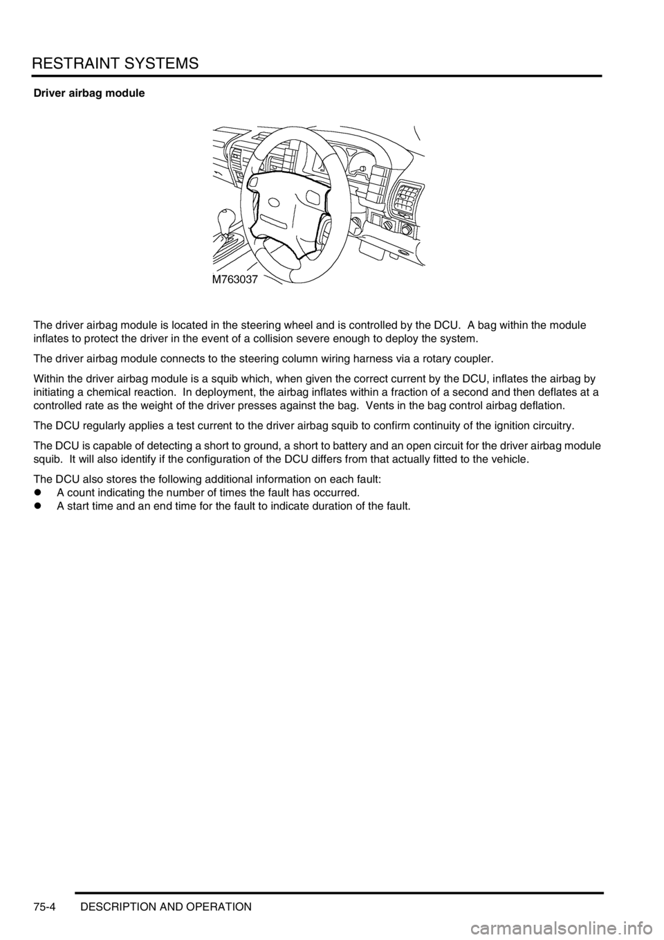
The driver airbag module is located in the steering wheel and is controlled by the DCU. A bag within the module
inflates to protect the driver in the event of a collision severe enough to deploy the system.
The driver airbag module connects to the steering column wiring harness via a rotary coupler.
Within the driver airbag module is a squib which, when given the correct current by the DCU, inflates the airbag by
initiating a chemical reaction. In deployment, the airbag inflates within a fraction of a second and then deflates at a
controlled rate as the weight of the driver presses against the bag. Vents in the bag control airbag deflation.
The DCU regularly applies a test current to the driver airbag squib to confirm continuity of the ignition circuitry.
The DCU is capable of detecting a short to ground, a short to battery and an open circuit for the driver airbag module
squib. It will also identify if the configuration of the DCU differs from that actually fitted to the vehicle.
The DCU also stores the following additional information on each fault:
lA count indicating the number of times the fault has occurred.
lA start time and an end time for the fault to indicate duration of the fault.
Page 908 of 1529

RESTRAINT SYSTEMS
DESCRIPTION AND OPERATION 75-5
Passenger airbag module
The passenger airbag module is located in the instrument panel above the glove box and is controlled by the DCU.
A bag within the module inflates to protect the passenger in the event of a collision severe enough to deploy the
system.
Within the passenger airbag module is a squib which, when given the correct current by the DCU, inflates the airbag
by initiating a chemical reaction. In deployment, the airbag inflates within a fraction of a second and then deflates at
a controlled rate as the weight of the passenger presses against the bag. Vents in the bag control airbag deflation.
The DCU regularly applies a test current to the passenger airbag squib to confirm continuity of the ignition circuitry.
The DCU is capable of detecting a short to ground, a short to battery and an open circuit for the passenger airbag
module squib. It will also identify if the configuration of the DCU differs from that actually fitted to the vehicle.
The DCU also stores the following additional information on each fault:
lA count indicating the number of times the fault has occurred.
lA start time and an end time for the fault to indicate duration of the fault.