key LAND ROVER DISCOVERY 1999 User Guide
[x] Cancel search | Manufacturer: LAND ROVER, Model Year: 1999, Model line: DISCOVERY, Model: LAND ROVER DISCOVERY 1999Pages: 1529, PDF Size: 34.8 MB
Page 200 of 1529
ENGINE - V8
OVERHAUL 12-2-45
OVERHAUL
Gasket - inlet manifold
$% 30.15.08.01
Disassembly
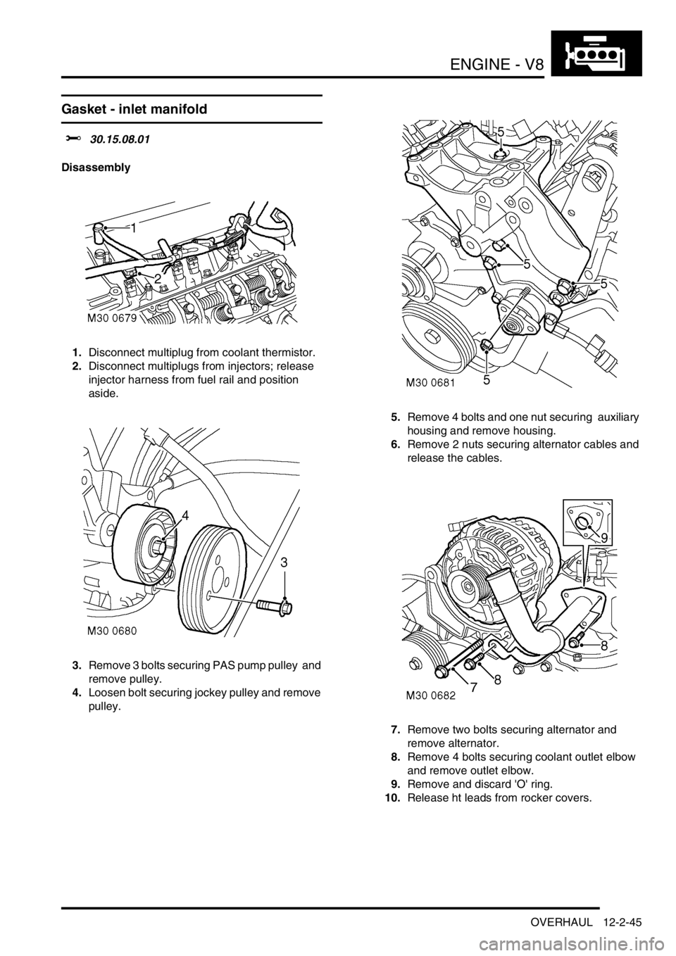
1.Disconnect multiplug from coolant thermistor.
2.Disconnect multiplugs from injectors; release
injector harness from fuel rail and position
aside.
3.Remove 3 bolts securing PAS pump pulley and
remove pulley.
4.Loosen bolt securing jockey pulley and remove
pulley. 5.Remove 4 bolts and one nut securing auxiliary
housing and remove housing.
6.Remove 2 nuts securing alternator cables and
release the cables.
7.Remove two bolts securing alternator and
remove alternator.
8.Remove 4 bolts securing coolant outlet elbow
and remove outlet elbow.
9.Remove and discard 'O' ring.
10.Release ht leads from rocker covers.
Page 203 of 1529
ENGINE - V8
12-2-48 OVERHAUL
21.Position alternator cables and tighten terminal
B+ to 18 Nm (13 lbf.ft) and terminal D+ to 5 Nm
(3.5 lbf.ft).
22.Position auxiliary housing, fit bolts and tighten
to 40 Nm (30 lbf.ft). Fit nut and tighten to 22 Nm
(17 lbf.ft).
23.Clean jockey pulley mating faces.
24.Position jockey pulley and tighten bolt to 50 Nm
(37 lbf.ft).
25.Clean PAS pump pulley mating faces.
26.Position PAS pump pulley, fit bolts and tighten
to 22 Nm (17 lbf.ft).
27.Secure injector harness and connect injector
multiplugs.
28.Connect multiplug to coolant thermistor.
Gasket - exhaust manifold
$% 30.15.12.01
Disassembly
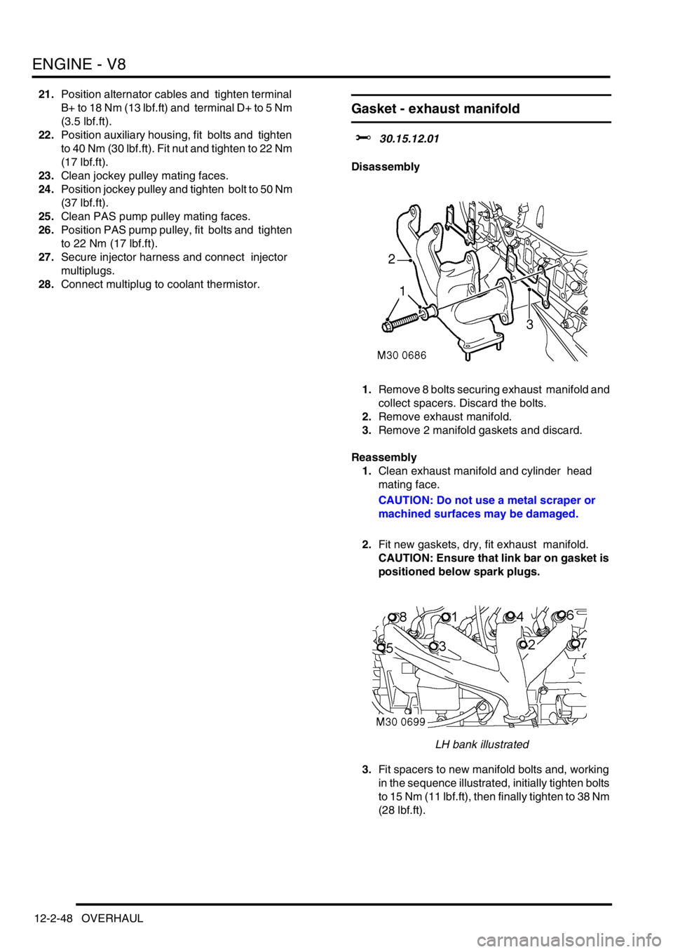
1.Remove 8 bolts securing exhaust manifold and
collect spacers. Discard the bolts.
2.Remove exhaust manifold.
3.Remove 2 manifold gaskets and discard.
Reassembly
1.Clean exhaust manifold and cylinder head
mating face.
CAUTION: Do not use a metal scraper or
machined surfaces may be damaged.
2.Fit new gaskets, dry, fit exhaust manifold.
CAUTION: Ensure that link bar on gasket is
positioned below spark plugs.
LH bank illustrated
3.Fit spacers to new manifold bolts and, working
in the sequence illustrated, initially tighten bolts
to 15 Nm (11 lbf.ft), then finally tighten to 38 Nm
(28 lbf.ft).
Page 212 of 1529
ENGINE - V8
OVERHAUL 12-2-57
Reassembly
1.Clean timing gear cover and mating face.
2.Clean oil seal register in timing gear cover.
3.Ensure bolt holes in cylinder block are clean
and dry, remove all traces of sealant from
threads of timing cover bolts.
4.Fit a new timing gear cover gasket, dry, to
timing cover locating dowels.
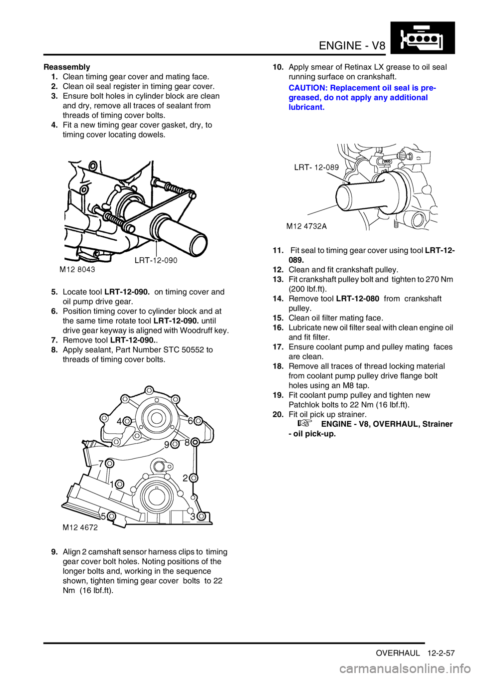
5.Locate tool LRT-12-090. on timing cover and
oil pump drive gear.
6.Position timing cover to cylinder block and at
the same time rotate tool LRT-12-090. until
drive gear keyway is aligned with Woodruff key.
7.Remove tool LRT-12-090..
8.Apply sealant, Part Number STC 50552 to
threads of timing cover bolts.
9.Align 2 camshaft sensor harness clips to timing
gear cover bolt holes. Noting positions of the
longer bolts and, working in the sequence
shown, tighten timing gear cover bolts to 22
Nm (16 lbf.ft). 10.Apply smear of Retinax LX grease to oil seal
running surface on crankshaft.
CAUTION: Replacement oil seal is pre-
greased, do not apply any additional
lubricant.
11. Fit seal to timing gear cover using tool LRT-12-
089.
12.Clean and fit crankshaft pulley.
13.Fit crankshaft pulley bolt and tighten to 270 Nm
(200 lbf.ft).
14.Remove tool LRT-12-080 from crankshaft
pulley.
15.Clean oil filter mating face.
16.Lubricate new oil filter seal with clean engine oil
and fit filter.
17.Ensure coolant pump and pulley mating faces
are clean.
18.Remove all traces of thread locking material
from coolant pump pulley drive flange bolt
holes using an M8 tap.
19.Fit coolant pump pulley and tighten new
Patchlok bolts to 22 Nm (16 lbf.ft).
20.Fit oil pick up strainer.
+ ENGINE - V8, OVERHAUL, Strainer
- oil pick-up.
Page 213 of 1529
ENGINE - V8
12-2-58 OVERHAUL
Timing chain and gears
$% 12.65.12.01
Disassembly
1.Remove timing gear cover gasket.
+ ENGINE - V8, OVERHAUL, Gasket -
timing gear cover.
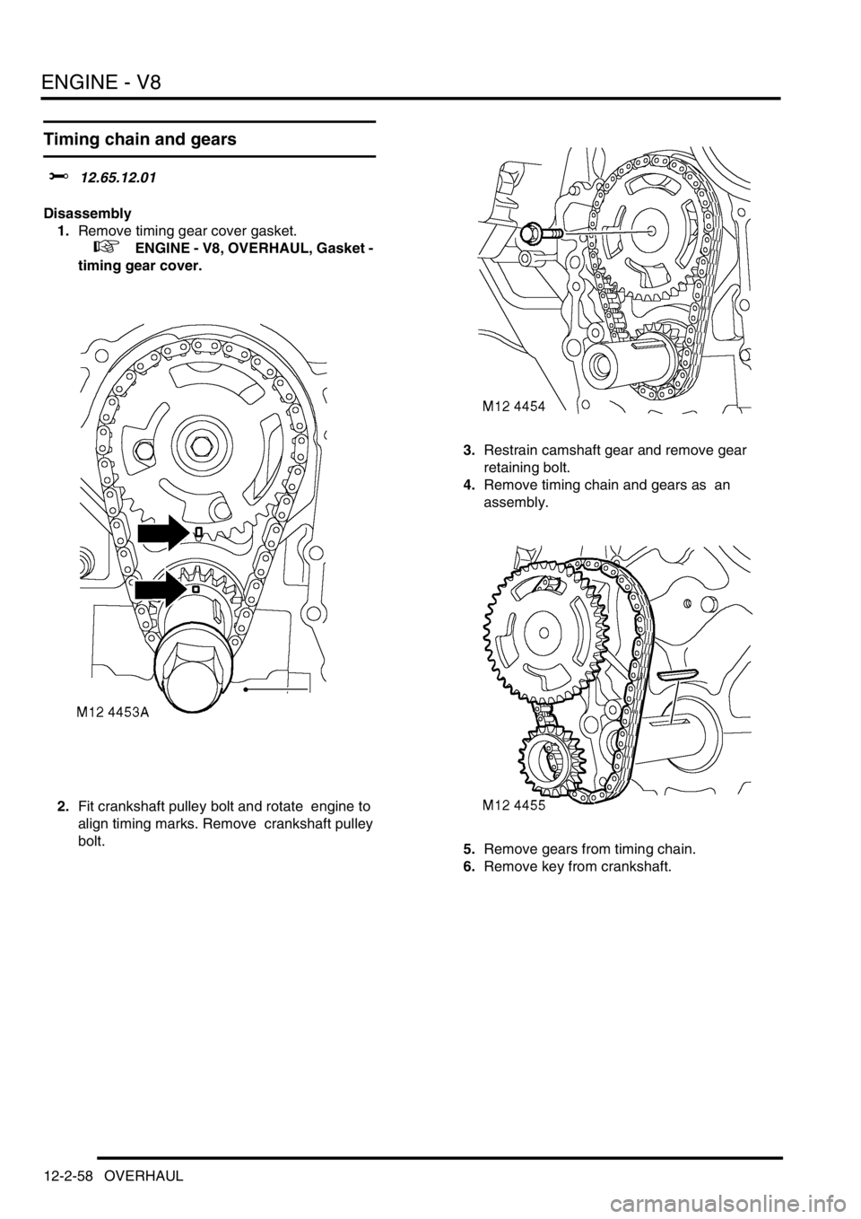
2.Fit crankshaft pulley bolt and rotate engine to
align timing marks. Remove crankshaft pulley
bolt. 3.Restrain camshaft gear and remove gear
retaining bolt.
4.Remove timing chain and gears as an
assembly.
5.Remove gears from timing chain.
6.Remove key from crankshaft.
Page 214 of 1529
ENGINE - V8
OVERHAUL 12-2-59
Reassembly
1.Clean timing chain and gears and gear
locations.
2.Fit key to crankshaft.
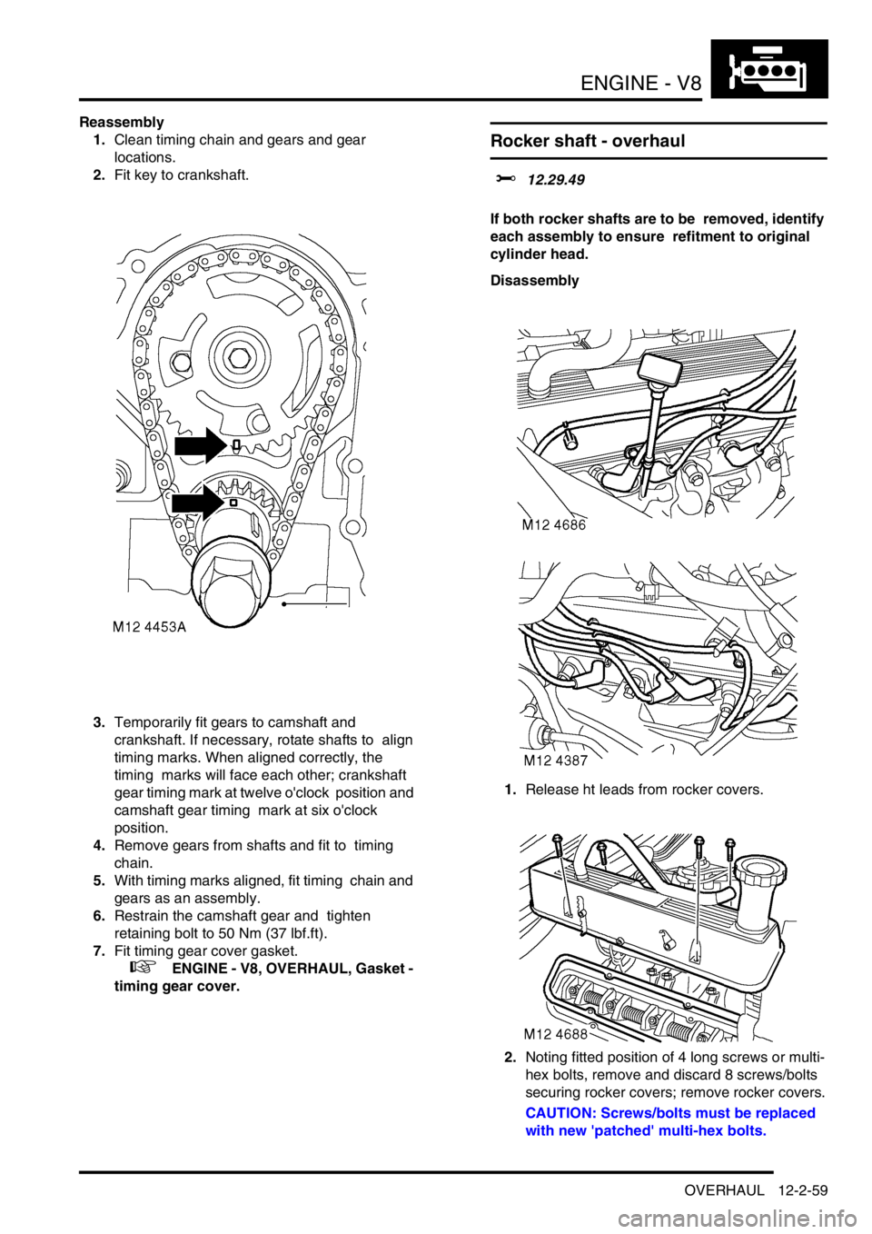
3.Temporarily fit gears to camshaft and
crankshaft. If necessary, rotate shafts to align
timing marks. When aligned correctly, the
timing marks will face each other; crankshaft
gear timing mark at twelve o'clock position and
camshaft gear timing mark at six o'clock
position.
4.Remove gears from shafts and fit to timing
chain.
5.With timing marks aligned, fit timing chain and
gears as an assembly.
6.Restrain the camshaft gear and tighten
retaining bolt to 50 Nm (37 lbf.ft).
7.Fit timing gear cover gasket.
+ ENGINE - V8, OVERHAUL, Gasket -
timing gear cover.
Rocker shaft - overhaul
$% 12.29.49
If both rocker shafts are to be removed, identify
each assembly to ensure refitment to original
cylinder head.
Disassembly
1.Release ht leads from rocker covers.
2.Noting fitted position of 4 long screws or multi-
hex bolts, remove and discard 8 screws/bolts
securing rocker covers; remove rocker covers.
CAUTION: Screws/bolts must be replaced
with new 'patched' multi-hex bolts.
Page 229 of 1529
ENGINE - V8
12-2-74 OVERHAUL
6.Reference mark main bearing caps to aid
assembly.
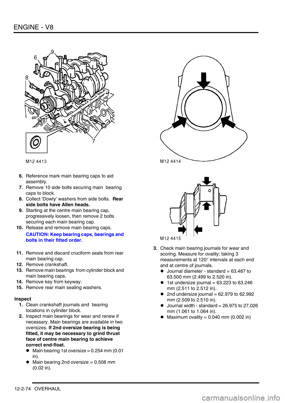
7.Remove 10 side bolts securing main bearing
caps to block.
8.Collect 'Dowty' washers from side bolts. Rear
side bolts have Allen heads.
9.Starting at the centre main bearing cap,
progressively loosen, then remove 2 bolts
securing each main bearing cap.
10.Release and remove main bearing caps.
CAUTION: Keep bearing caps, bearings and
bolts in their fitted order.
11.Remove and discard cruciform seals from rear
main bearing cap.
12.Remove crankshaft.
13.Remove main bearings from cylinder block and
main bearing caps.
14.Remove key from keyway.
15.Remove rear main sealing washers.
Inspect
1.Clean crankshaft journals and bearing
locations in cylinder block.
2.Inspect main bearings for wear and renew if
necessary. Main bearings are available in two
oversizes. If 2nd oversize bearing is being
fitted, it may be necessary to grind thrust
face of centre main bearing to achieve
correct end-float.
lMain bearing 1st oversize = 0.254 mm (0.01
in).
lMain bearing 2nd oversize = 0.508 mm
(0.02 in).3.Check main bearing journals for wear and
scoring. Measure for ovality; taking 3
measurements at 120° intervals at each end
and at centre of journals.
lJournal diameter - standard = 63.487 to
63.500 mm (2.499 to 2.520 in).
l1st undersize journal = 63.223 to 63.246
mm (2.511 to 2.512 in).
l2nd undersize journal = 62.979 to 62.992
mm (2.509 to 2.510 in).
lJournal width - standard = 26.975 to 27.026
mm (1.061 to 1.064 in).
lMaximum ovality = 0.040 mm (0.002 in)
Page 230 of 1529

ENGINE - V8
OVERHAUL 12-2-75
Reassembly
1.Clean main bearing locations in cylinder block
and bearing caps; ensure bolt holes are clean
and dry.
2.Clean sealant from rear main bearing cap and
mating faces.
3.Fit key to keyway.
4.Check threads of main bearing cap bolts for
damage, renew bolts in pairs.
5.Lubricate grooved main bearing shells with
clean engine oil and fit to their locations in
cylinder block.
NOTE: Ensure that the flanged bearing is fitted
to the centre position.
6.Lubricate crankshaft journals with clean engine
oil.
7.Position crankshaft in cylinder block.
8.Lubricate plain bearing shells with clean
engine oil and fit to main bearing caps.
9.Fit main bearing caps 1 to 4 only at this stage,
ensuring that they are the correct way round
and in their fitted order.
10.Lightly lubricate threads of main bearing cap
bolts with clean engine oil.
11.Fit main bearing cap bolts but do not tighten at
this stage. Do not fit side bolts at this stage.12.Lubricate new cruciform seals with engine oil
and fit to rear main bearing cap.
CAUTION: Do not trim off excess from
cruciform seals at this stage.
13.Apply a 3 mm (0.12 in) wide bead of sealant,
Part No. STC 50550 to bearing cap rear mating
faces on cylinder block.
CAUTION: Ensure sealant does not enter
bolt holes.
14.Carefully fit rear main bearing cap assembly, fit
but do not tighten bolts.
CAUTION: Ensure engine oil does not enter
the side bolt holes in the bearing cap. Do
not trim off excess material from cruciform
seals at this stage.
15.Lubricate 'Dowty' washers with engine oil and
fit to side bolts.
16.Fit but do not tighten side bolts. Rear side
bolts are Allen headed.
17.Using the sequence shown, tighten main
bearing cap bolts as follows:
lInitial torque - all main bearing cap bolts and
side bolts - 13.5 Nm (10 lbf.ft).
lFinal torque - main bearing cap side bolts 11
to 15 - 45 Nm (34 lbf.ft).
lFinal torque - main bearing cap bolts 1 to 8
- 72 Nm (54 lbf.ft).
lFinal torque - main bearing cap bolts 9 and
10 - 92 Nm (68 lbf.ft).
lFinal torque - main bearing cap side bolts 16
to 20 - 45 Nm (34 lbf.ft).
18.Trim off excess material from cruciform seals.
Page 396 of 1529

ENGINE MANAGEMENT SYSTEM - V8
REPAIRS 18-2-97
Switch - cruise control (set/resume)
$% 19.75.33
Remove
1.Remove the key from the starter switch.
Disconnect both battery leads, negative lead
first. Wait ten minutes before starting work.
2.Remove driver's airbag module.
+ RESTRAINT SYSTEMS, REPAIRS,
Airbag module - drivers.
3.Release remote control switches multiplug and
leads from steering wheel base.
4.Disconnect remote control switches multiplug
from harness.
5.Remove 2 screws securing remote control
switches to steering wheel base.
6.Release and remove remote control switches
from steering wheel.
Refit
1.Fit remote control switches to steering wheel
and secure with screws.
2.Connect remote control switches multiplug to
harness.
3.Secure leads and multiplug to base of steering
wheel.
4.Fit driver's airbag module.
+ RESTRAINT SYSTEMS, REPAIRS,
Airbag module - drivers.
Switch - clutch pedal - cruise control
$% 19.75.34
Remove
1.Remove 3 fasteners and move driver's side
lower closing panel aside.
2.Disconnect multiplug from clutch pedal switch.
3.Remove switch from pedal bracket.
Refit
1.Engage switch fully into pedal bracket location
and connect multiplug.
2.Position lower closing panel and secure with
fasteners.
Page 446 of 1529

MANIFOLDS AND EXHAUST SYSTEMS - V8
REPAIRS 30-2-11
5.Remove 3 bolts securing ACE pump, release
pump and position aside.
6.Remove 2 bolts securing alternator and
remove alternator. 7.Remove 3 bolts securing PAS pump pulley and
remove pulley.
8.Remove jockey pulley.
9.Position tray to catch spillage, release PAS
pump high pressure pipe.
CAUTION: Always fit plugs to open
connections to prevent contamination.
10.Remove bolt securing oil cooling pipe and
release bracket from auxiliary housing.
11.Remove two bolts securing PAS pump.
12.Remove 5 bolts and one nut securing auxiliary
housing. Pull housing forward, release PAS
pump and remove housing.
Page 448 of 1529

MANIFOLDS AND EXHAUST SYSTEMS - V8
REPAIRS 30-2-13
20.Remove inlet manifold gasket.
21.Remove gasket seals.
Refit
1.Clean all traces of sealant from cylinder head
and cylinder block notches.
2.Clean mating faces of cylinder block, cylinder
head and inlet manifold.
3.Apply sealant, Part No. STC 50550 to cylinder
head and cylinder block notches.
4.Fit new gasket seals, ensuring ends engage
correctly in notches.
5.Fit new inlet manifold gasket.
6.Position gasket clamps and fit bolts, but do not
tighten at this stage.
7.Position inlet manifold to engine. Fit manifold
bolts and, working in the sequence shown,
tighten bolts initially to 10 Nm (7 lbf.ft) then to
51 Nm (38 lbf.ft).
8.Tighten gasket clamp bolts to 18 Nm (13 lbf.ft).
9.Connect fuel pipe.
10.Clean top hose outlet pipe mating faces.
11.Fit new 'O' ring to outlet pipe.
12.Position outlet pipe, fit bolts and tighten to 22
Nm (16 lbf.ft).
13.Position alternator, fit bolts and tighten to 45
Nm (33 lbf.ft).
14.Position PAS pump to auxiliary housing and
locate housing on engine. Fit bolts and tighten
to 40 Nm (30 lbf.ft).15.Fit and tighten auxiliary housing nut to 10 Nm (7
lbf.ft).
16.Fit bolts securing PAS pump and tighten to 22
Nm (16 lbf.ft).
17.Position oil cooling pipe bracket fit bolt and
tighten to 22 Nm (16 lbf.ft).
18.Fit and tighten PAS pump high pressure pipe.
19.Position jockey pulley and tighten bolt to 50 Nm
(37 lbf.ft).
20.Clean PAS pump pulley mating faces.
21.Position PAS pump pulley, fit bolts and tighten
to 22 Nm (16 lbf.ft).
22.Clean ACE pump dowels and dowel holes.
23.Position ACE pump, fit bolts and tighten to 22
Nm (16 lbf.ft).
24.Fit auxiliary drive belt.
+ CHARGING AND STARTING,
REPAIRS, Belt - auxiliary drive.
25.Secure injector harness and connect injector
multiplugs.
26.Position top hose and secure clips.
27.Fit rocker covers.
l
+ ENGINE - V8, REPAIRS, Gasket
- rocker cover - LH.
l
+ ENGINE - V8, REPAIRS, Gasket
- rocker cover - RH.
28.Check and top up PAS fluid