LAND ROVER DISCOVERY 1999 Workshop Manual
Manufacturer: LAND ROVER, Model Year: 1999, Model line: DISCOVERY, Model: LAND ROVER DISCOVERY 1999Pages: 1529, PDF Size: 34.8 MB
Page 391 of 1529

ENGINE MANAGEMENT SYSTEM - V8
18-2-92 REPAIRS
Valve - idle air control (IACV)
$% 19.22.54
Remove
1.Disconnect multiplug from IACV.
2.Loosen 2 clips securing air hoses and release
hoses.
3.Remove 2 screws securing IACV to inlet
manifold.
4.Collect clamps and remove IACV.
Refit
1.Position IACV to inlet manifold, locate clamps,
fit screws and tighten to 8 Nm (6 lbf.ft).
2.Position air hoses to IACV and secure clips.
3.Connect multiplug to IACV.
Injectors
$% 19.60.12
Remove
1.Remove upper manifold.
+ MANIFOLDS AND EXHAUST
SYSTEMS - V8, REPAIRS, Gasket - inlet
manifold - upper - Without Secondary Air
Injection.
2.Carefully manoeuvre ignition coil assembly
from between inlet manifold and bulkhead.
3.Position absorbent cloth beneath fuel pipe to
catch spillage.
4.Disconnect fuel feed hose from fuel rail
CAUTION: Always fit plugs to open
connections to prevent contamination.
5.Release injector harness from fuel rail and
disconnect injector multiplugs.
Page 392 of 1529

ENGINE MANAGEMENT SYSTEM - V8
REPAIRS 18-2-93
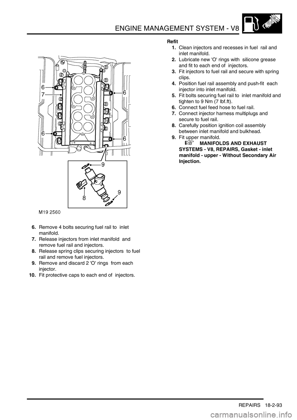
6.Remove 4 bolts securing fuel rail to inlet
manifold.
7.Release injectors from inlet manifold and
remove fuel rail and injectors.
8.Release spring clips securing injectors to fuel
rail and remove fuel injectors.
9.Remove and discard 2 'O' rings from each
injector.
10.Fit protective caps to each end of injectors. Refit
1.Clean injectors and recesses in fuel rail and
inlet manifold.
2.Lubricate new 'O' rings with silicone grease
and fit to each end of injectors.
3.Fit injectors to fuel rail and secure with spring
clips.
4.Position fuel rail assembly and push-fit each
injector into inlet manifold.
5.Fit bolts securing fuel rail to inlet manifold and
tighten to 9 Nm (7 lbf.ft).
6.Connect fuel feed hose to fuel rail.
7.Connect injector harness multiplugs and
secure to fuel rail.
8.Carefully position ignition coil assembly
between inlet manifold and bulkhead.
9.Fit upper manifold.
+ MANIFOLDS AND EXHAUST
SYSTEMS - V8, REPAIRS, Gasket - inlet
manifold - upper - Without Secondary Air
Injection.
Page 393 of 1529

ENGINE MANAGEMENT SYSTEM - V8
18-2-94 REPAIRS
Actuator - cruise control
$% 19.75.05
Remove
1.Release clip and disconnect inner cable from
actuator.
2.Release outer cable from actuator mounting
bracket.
3.Release vacuum hose from actuator.
4.Remove nut, and remove actuator from
mounting bracket.
Refit
1.Position actuator and tighten retaining nut.
2.Connect vacuum hose to actuator.
3.Connect outer cable to mounting bracket.
4.Connect inner cable to actuator.
Vacuum control unit - up to 03MY
$% 19.75.06
Remove
1.Disconnect vacuum hose from actuator.
2.Disconnect multiplug from vacuum control unit.
3.Release 3 rubber mountings securing control
unit, and remove from mounting bracket.
4.Remove vacuum hose from control unit.
Refit
1.Position vacuum hose to control unit.
2.Position control unit and secure mountings.
3.Connect multiplug and vacuum hose.
Page 394 of 1529

ENGINE MANAGEMENT SYSTEM - V8
REPAIRS 18-2-95
Vacuum control unit - from 03MY
$% 19.75.06
Remove
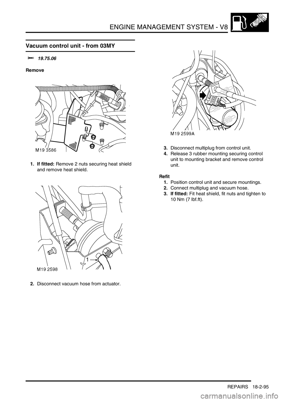
1. If fitted: Remove 2 nuts securing heat shield
and remove heat shield.
2.Disconnect vacuum hose from actuator.3.Disconnect multiplug from control unit.
4.Release 3 rubber mounting securing control
unit to mounting bracket and remove control
unit.
Refit
1.Position control unit and secure mountings.
2.Connect multiplug and vacuum hose.
3. If fitted: Fit heat shield, fit nuts and tighten to
10 Nm (7 lbf.ft).
Page 395 of 1529

ENGINE MANAGEMENT SYSTEM - V8
18-2-96 REPAIRS
Cable - cruise control
$% 19.75.10
Remove
1.Release clip and disconnect inner cable from
actuator.
2.Release outer cable from actuator mounting
bracket.
3.Loosen cable locknuts, release outer cable
from abutment bracket and retaining clip.
4.Release inner cable from operating lever and
remove cable.
Refit
1.Position cable and connect to operating lever.
2.Position cable to abutment bracket.
3.Position outer cable to actuator mounting
bracket and connect inner cable to actuator.
4.Adjust cruise control cable.
+ ENGINE MANAGEMENT SYSTEM -
V8, ADJUSTMENTS, Cable - cruise control.
Switch - cruise control (on/off)
$% 19.75.30
Remove
1.Carefully remove switch from instrument cowl.
2.Disconnect multiplug and remove switch.
Refit
1.Position new switch and connect multiplug.
2.Carefully push switch into instrument cowl.
Page 396 of 1529

ENGINE MANAGEMENT SYSTEM - V8
REPAIRS 18-2-97
Switch - cruise control (set/resume)
$% 19.75.33
Remove
1.Remove the key from the starter switch.
Disconnect both battery leads, negative lead
first. Wait ten minutes before starting work.
2.Remove driver's airbag module.
+ RESTRAINT SYSTEMS, REPAIRS,
Airbag module - drivers.
3.Release remote control switches multiplug and
leads from steering wheel base.
4.Disconnect remote control switches multiplug
from harness.
5.Remove 2 screws securing remote control
switches to steering wheel base.
6.Release and remove remote control switches
from steering wheel.
Refit
1.Fit remote control switches to steering wheel
and secure with screws.
2.Connect remote control switches multiplug to
harness.
3.Secure leads and multiplug to base of steering
wheel.
4.Fit driver's airbag module.
+ RESTRAINT SYSTEMS, REPAIRS,
Airbag module - drivers.
Switch - clutch pedal - cruise control
$% 19.75.34
Remove
1.Remove 3 fasteners and move driver's side
lower closing panel aside.
2.Disconnect multiplug from clutch pedal switch.
3.Remove switch from pedal bracket.
Refit
1.Engage switch fully into pedal bracket location
and connect multiplug.
2.Position lower closing panel and secure with
fasteners.
Page 397 of 1529

ENGINE MANAGEMENT SYSTEM - V8
18-2-98 REPAIRS
ECU - Cruise control
$% 19.75.49
Remove
1.Remove fixings securing fascia RH closing
panel and remove panel.
2.Remove 2 fixings and remove 'A' post lower
trim.
3.Remove 2 nuts and remove ECU from studs.
4.Disconnect multiplug from ECU and remove
ECU.
Refit
1.Position new ECU and connect multiplug.
2.Fit ECU to studs and secure with nuts.
3.Fit lower trim panel to 'A' post and secure with
fixings.
4.Fit closing panel and secure with fixings.
5.Programme the ECU using TestBook.
Page 398 of 1529

FUEL DELIVERY SYSTEM - V8
DESCRIPTION AND OPERATION 19-2-1
FUEL DELIVERY SYST EM - V8 DESCRIPTION AND OPERAT ION
Fuel delivery system
1Fuel pressure regulator (hidden)
2Schraeder valve
3Fuel rail
4Injectors
5Engine block6Fuel feed pipe
7Coarse filter
8Fine filter
9Fuel pump and fuel gauge sender assembly
Page 399 of 1529

FUEL DELIVERY SYSTEM - V8
19-2-2 DESCRIPTION AND OPERATION
Fuel tank and breather components (all
except NAS)
1Fuel filler cap
2Relief valve
3Vent to EVAP canister
4Tank breather connection
5Fuel pump, regulator and fuel gauge sender
assembly
6Seal
7Locking ring
8Fuel feed connection
9Fuel gauge sender float
10Fuel tank and breather assembly
11Heat shield
12Scrivet 2 off13Stud plate
14Nut 2 off
15Cradle
16Bolt 2 off
17Nut plate 2 off
18Hose clip 2 off
19Hose
20Vent hose
21Vent hose coupling
22Hose clip 2 off
23Hose
24Filler tube
25Liquid Vapour Separator (LVS)
Page 400 of 1529

FUEL DELIVERY SYSTEM - V8
DESCRIPTION AND OPERATION 19-2-3
Fuel tank and breather components
(NAS)
1Fuel filler cap
2Filler tube
3OBD pressure sensor atmospheric pipe
4Vent pipe to EVAP canister
5Fuel pump, regulator and fuel gauge sender
assembly
6OBD pressure sensor (vacuum type, EVAP
system leak detection capability only)
7Seal
8Locking ring
9Fuel feed connection
10Fuel gauge sender float
11Fuel tank and breather assembly12Heat shield
13Scrivet 2 off
14Stud plate
15Nut 2 off
16Cradle
17Bolt 2 off
18Nut plate 2 off
19Hose clip
20LVS vent pipe
21Tank breather connection
22Liquid vapour separator (LVS)
23Anti-trickle fill valve