LAND ROVER DISCOVERY 1999 Workshop Manual
Manufacturer: LAND ROVER, Model Year: 1999, Model line: DISCOVERY, Model: LAND ROVER DISCOVERY 1999Pages: 1529, PDF Size: 34.8 MB
Page 701 of 1529

STEERING
57-8 DESCRIPTION AND OPERATION
Steering box
The steering box is located behind the first cross member of the chassis and is secured to the chassis rail with four
bolts. The steering box is of the worm and roller type and has a rotary control valve. The steering box is connected to
the steering knuckles of the front road wheels by the drop arm, drag link and track rod. The steering box is lubricated
by the hydraulic fluid in the housing. The input shaft is attached to the steering wheel via the intermediate shaft and
steering column. The drop arm is secured to the output shaft with a nut and tab washer. A ball joint allows movement
between drop arm and drag link, the ball joint is secured with a locknut. The steering box requries approximately 3.5
turns from lock to lock.
As a maintenance aid, an alignment bolt can be used to lock the drop arm at the steering box centre position. The bolt
fits in a groove in the rear face of the drop arm and screws in to a threaded hole on the bottom of the steering box
housing.
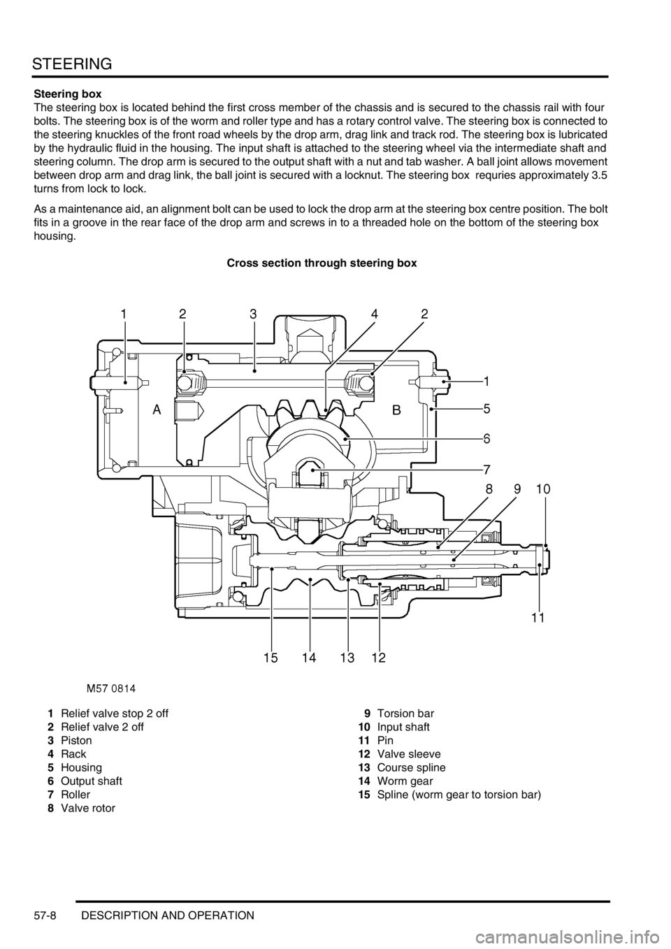
Cross section through steering box
1Relief valve stop 2 off
2Relief valve 2 off
3Piston
4Rack
5Housing
6Output shaft
7Roller
8Valve rotor9Torsion bar
10Input shaft
11Pin
12Valve sleeve
13Course spline
14Worm gear
15Spline (worm gear to torsion bar)
Page 702 of 1529

STEERING
DESCRIPTION AND OPERATION 57-9
Principle of operation
Movement of the input shaft is transferred through the pin to the torsion bar and valve rotor on the input shaft. As the
input shaft turns, the spline of the torsion bar turns the worm gear. This action causes the roller to rotate on its bearings
and move. As the roller is located by a pin to a yoke on the output shaft, the output shaft rotates in the steering box
housing. As the amount of torque acting on the input shaft increases the torsion bar starts to twist. As the torsion bar
twists the valve rotor turns in the valve sleeve. When the ports in the valve rotor and valve sleeve are turned, hydraulic
fluid is directed to chamber 'A' or 'B' in the power cylinder.
With hydraulic fluid in one chamber under high pressure, the piston moves. The return line ports in the rotary valve,
aligned by the movement of the valve rotor, allow the fluid in the opposite chamber to flow to return. The teeth of the
rack move and transfer the force from the piston to the output shaft, giving assistance to move the drop arm. As the
output shaft rotates the torsion bar load is decreased. The rotor on the input shaft will return as the torsion bar
unwinds, the rotary valve will then be in a neutral position and the pressure in chambers 'A' and 'B' will equalise. With
no high pressure acting on the piston, force on the piston and rack is released.
To prevent heat accumulation at full steering lock due to excessive pressure, a relief valve inside the steering box is
opened as the box approaches full lock. The relief valve pins are located in the cylinder cover and housing and are
not to be adjusted.
The steering box design ensures a mechanical link through the course spline on the control valve rotor, the spline will
become engaged if:
lThe hydraulic pressure fails.
lThe steering box rotary control valve fails.
The coarse spline may also engage in some full lock situations if sufficient torque is applied to the input shaft.
Page 703 of 1529

STEERING
57-10 DESCRIPTION AND OPERATION
Rotary control valve
The rotary valve assembly comprises of three parts. The valve sleeve is fixed inside one end of the worm gear, the
valve sleeve has ports through it to allow the passage of hydraulic fluid. The input shaft has a valve rotor machined
on one end, the valve rotor also has ports through it and can rotate in the valve sleeve. A torsion bar is attached to
the input shaft by a pin, the torsion bar goes through the input shaft and valve rotor and is engaged by a spline into
the worm gear.
The coarse spline on the end of the valve rotor is loosely engaged in the worm gear, the coarse spline can make
contact and drive the worm gear in some full lock and in no pressure conditions. In the event of a torsion bar failure,
power assistance will be lost, the coarse spline will drive the worm gear and enable the vehicle to be steered and
driver control maintained.
Rotary control valve at neutral
1Worm gear
2Torsion bar
3Valve sleeve
4Pin5Input shaft and valve rotor
6Piston/rack
7Coarse spline
8Spline (torque shaft to worm gear)
When there is no demand for assistance the torsion bar holds the ports in the valve sleeve and valve rotor in a neutral
relationship to one another. The ports in the valve sleeve and the valve rotor are so aligned to allow equal (low) fluid
pressure on each side of the piston. Excess fluid flows through ports in the valve rotor through the valve sleeve and
back to the reservoir.
Page 704 of 1529

STEERING
DESCRIPTION AND OPERATION 57-11
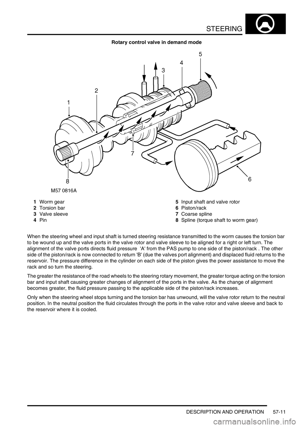
Rotary control valve in demand mode
1Worm gear
2Torsion bar
3Valve sleeve
4Pin5Input shaft and valve rotor
6Piston/rack
7Coarse spline
8Spline (torque shaft to worm gear)
When the steering wheel and input shaft is turned steering resistance transmitted to the worm causes the torsion bar
to be wound up and the valve ports in the valve rotor and valve sleeve to be aligned for a right or left turn. The
alignment of the valve ports directs fluid pressure 'A' from the PAS pump to one side of the piston/rack . The other
side of the piston/rack is now connected to return 'B' (due the valves port alignment) and displaced fluid returns to the
reservoir. The pressure difference in the cylinder on each side of the piston gives the power assistance to move the
rack and so turn the steering.
The greater the resistance of the road wheels to the steering rotary movement, the greater torque acting on the torsion
bar and input shaft causing greater changes of alignment of the ports in the valve. As the change of alignment
becomes greater, the fluid pressure passing to the applicable side of the piston/rack increases.
Only when the steering wheel stops turning and the torsion bar has unwound, will the valve rotor return to the neutral
position. In the neutral position the fluid circulates through the ports in the valve rotor and valve sleeve and back to
the reservoir where it is cooled.
Page 705 of 1529

STEERING
57-12 DESCRIPTION AND OPERATION
PAS pump - V8
1Bolt 2 off
2Nut
3Stud
4Auxiliary housing
5PAS pump6Outlet
7Inlet
8Bolt 3 off
9Drive pulley
The PAS pump is located on the auxiliary housing and is attached by two bolts, the bolts go through flanged bushes
in the auxiliary housing. A stud passes through the PAS pump and through a flanged bush in the auxiliary housing,
the auxiliary housing and PAS pump are secured by a nut. As the two bolts and nut are tightened the bushes move
slightly and the flange of each bush clamps the PAS pump. A drive pulley is attached to the pump drive shaft with
three bolts, and is belt driven at a ratio of 1.4 crankshaft revolutions to 1 of the drive pulley. Fluid is drawn into the
PAS pump inlet from the reservoir through a flexible hose at low (suction) pressure. Fluid at high pressure from the
PAS pump outlet is supplied to the rotary control valve on the steering box.
The PAS pump is a roller vane type and has an internal pressure regulator and flow control valve. The roller vanes
can move in slots in the pumps rotor and are moved outwards by centrifugal force as the pump rotates. The pump
rotor rotates in the pump housing, the internal shape of the housing forms a 'cam' shape. Due to the 'cam' shape the
volume of the housing decreases between the inlet and outlet ports.
As the pump rotor rotates towards the pump inlet the volume between the roller vanes and the pump housing
increases, this action causes a depression in the chamber between the pump roller vanes and the housing. As the
rotation continues the chamber is opened to the pump inlet, and the depression in the chamber causes fluid to be
drawn in. The roller vanes continue past the inlet port, closing off the inlet port and trapping the fluid in the chamber
between the rollers and the pump housing.
Page 706 of 1529

STEERING
DESCRIPTION AND OPERATION 57-13
The internal 'cam' shape of the pump housing causes the rollers to move closer together as the pump rotor rotates
towards the outlet port. The reduced volume of the chamber between the roller vanes causes the fluid to become
pressurised. When the chamber is opened to the outlet port of the pump the fluid escapes at high pressure. The roller
vanes continue turning and go past the outlet port, closing off the chamber between the two roller vanes.
As rotation continues the inlet sequence begins again. The inlet and pressurisation/outlet sequences continue as the
pump rotates, and is repeated between each two roller vanes. The pump is a positive displacement type and the
potential pump output increases with engine (drive pulley) speed. The pressure relief and flow control valve regulates
flow/pressure by diverting fluid back to the pump inlet through internal recirculation passages in the pump body.
Page 707 of 1529

STEERING
57-14 DESCRIPTION AND OPERATION
PAS pump - diesel
1Drive pulley
2Mounting bracket
3Bolt 2 off
4Bolt
5PAS pump
6Coupling7Auxiliary housing
8Outlet
9Inlet adaptor pipe and seal
10Bolt 2 off
11Bolt 2 off
12Bolt 3 off
The PAS pump is located on the auxiliary housing, two bolts go through the PAS pump, mounting bracket and into
the auxiliary housing. One bolt also attaches the mounting bracket to the PAS pump, two bolts secure the mounting
bracket to the auxiliary housing. An inlet adaptor pipe with a seal is secured to the bottom of the pump with two bolts.
A drive pulley is attached to the pump drive shaft with three bolts, and is belt driven at a ratio of 1.35 crankshaft
revolutions to 1 of the drive pulley. A coupling on the rear of the PAS pump rotates the water pump impeller located
in the auxiliary housing. Fluid is supplied to the PAS pump inlet from the reservoir through a flexible hose at low
(suction) pressure. Fluid at high pressure from the PAS pump outlet is supplied to the rotary control valve on the
steering box.
The PAS pump is a roller vane type and has an internal pressure regulator and flow control valve. The roller vanes
can move in slots in the pumps rotor and are moved outwards by centrifugal force as the pump rotates. The pump
rotor rotates in the pump housing, the internal shape of the housing forms a 'cam' shape. Due to the 'cam' shape the
volume of the housing decreases between the inlet and outlet ports.
Page 708 of 1529

STEERING
DESCRIPTION AND OPERATION 57-15
As the pump rotor rotates towards the pump inlet the volume between the roller vanes and the pump housing
increases, this action causes a depression in the chamber between the pump roller vanes and the housing. As the
rotation continues the chamber is opened to the pump inlet, and the depression in the chamber causes fluid to be
drawn in. The roller vanes continue past the inlet port, closing off the inlet port and trapping the fluid in the chamber
between the rollers and the pump housing.
The internal 'cam' shape of the pump housing causes the rollers to move closer together as the pump rotor rotates
towards the outlet port. The reduced volume of the chamber between the roller vanes causes the fluid to become
pressurised. When the chamber is opened to the outlet port of the pump the fluid escapes at high pressure. The roller
vanes continue turning and go past the outlet port, closing off the chamber between the two roller vanes.
As rotation continues the inlet sequence begins again. The inlet and pressurisation/outlet sequences continue as the
pump rotates, and is repeated between each two roller vanes. The pump is a positive displacement type and the
potential pump output increases with engine (drive pulley) speed. The pressure relief and flow control valve regulates
flow/pressure by diverting fluid back to the pump inlet through internal recirculation passages in the pump body.
Steering damper
The steering damper is located behind and just below the first cross member of the chassis. The ends of the steering
damper have steel 'eyes' welded on, rubber bushes are installed in each 'eye'. The steering damper is attached
between brackets on the chassis rail and the drag link. Each end of the steering damper is secured by a bolt and
locknut. The hydraulic damper absorbs shocks in the steering, caused by road wheel deflections when operating on
rough terrain.
Page 709 of 1529

STEERING
57-16 DESCRIPTION AND OPERATION
Operation
Hydraulic fluid is supplied to the PAS pump inlet from the PAS reservoir, the PAS pump draws in and pressurises the
fluid. The PAS pump self regulates internal flow rates and operating pressure, and supplies pressurised fluid from the
PAS pump outlet to a rotary control valve in the steering box. At neutral the fluid is circulated by the PAS pump and
flows around the system at a lower pressure and a constant flow rate. With most of the fluid being returned to the
reservoir the pressure inside the system remains very low. When a control input turns the rotary control valve in the
steering box, pressure in the system will rise as the control valve directs fluid to give power assistance.
The action of turning the steering wheel turns the steering column and intermediate shaft. The intermediate shaft turns
the input shaft of the steering box. The input shaft moves the rotary control valve in the steering box, the rotary valve
controls the pressure used inside the steering box for power assistance. The input shaft also turns a worm gear, the
worm gear acts on a roller attached to the output shaft. As the worm gear turns the roller, the roller travels along the
lands of the worm gear. As the roller is attached to the output shaft the output shaft turns.
As the output shaft of the steering box turns, hydraulic pressure is supplied via the rotary control valve to the steering
box. The hydraulic pressure acts on a rack that assists with the movement of the output shaft of the steering box. A
drop arm is attached to the output shaft of the steering box. The drop arm is connected to a drag link by a ball joint.
The drag link is connected via ball joints to one front steering knuckle and road wheel. A track rod connected to this
steering knuckle links the two steering knuckles together. As one steering knuckle and road wheel is turned by the
drag link, the other steering knuckle and wheel is moved by the track rod.
Page 710 of 1529

STEERING
ADJUSTMENTS 57-17
ADJUST ME NTS
Steering box - check and adjust
$% 57.10.13
Check
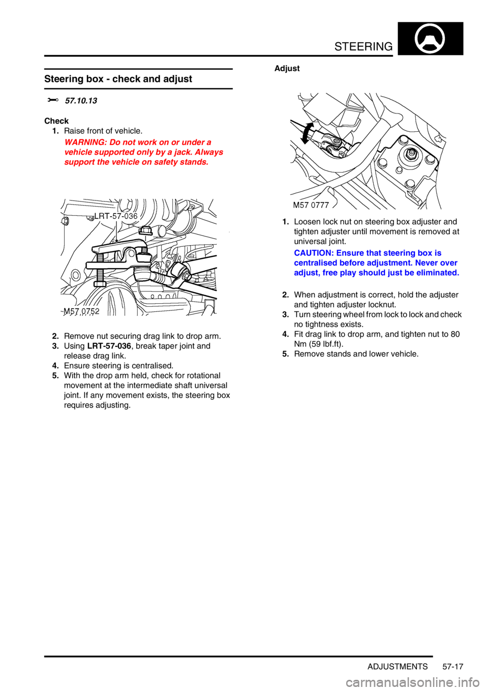
1.Raise front of vehicle.
WARNING: Do not work on or under a
vehicle supported only by a jack. Always
support the vehicle on safety stands.
2.Remove nut securing drag link to drop arm.
3.Using LRT-57-036, break taper joint and
release drag link.
4.Ensure steering is centralised.
5.With the drop arm held, check for rotational
movement at the intermediate shaft universal
joint. If any movement exists, the steering box
requires adjusting.Adjust
1.Loosen lock nut on steering box adjuster and
tighten adjuster until movement is removed at
universal joint.
CAUTION: Ensure that steering box is
centralised before adjustment. Never over
adjust, free play should just be eliminated.
2.When adjustment is correct, hold the adjuster
and tighten adjuster locknut.
3.Turn steering wheel from lock to lock and check
no tightness exists.
4.Fit drag link to drop arm, and tighten nut to 80
Nm (59 lbf.ft).
5.Remove stands and lower vehicle.