oil temperature LAND ROVER DISCOVERY 1999 Workshop Manual
[x] Cancel search | Manufacturer: LAND ROVER, Model Year: 1999, Model line: DISCOVERY, Model: LAND ROVER DISCOVERY 1999Pages: 1529, PDF Size: 34.8 MB
Page 6 of 1529

CONTENTS
CONTENTS 3
MAINTENANCE ........................................................................................ 10-1
PROCEDURES
V8 engine underbonnet view .......................................................................................................... 10-1
Diesel underbonnet view ................................................................................................................. 10-2
Seats and seat belts ...................................................................................................................... 10-3
Lamps, horns and warning indicators ............................................................................................. 10-5
Wipers and washers ...................................................................................................................... 10-5
Handbrake .................................................................................................................................. 10-6
Alarm handset battery ..................................................................................................................... 10-6
Road wheels ................................................................................................................................... 10-6
Tyres .............................................................................................................................................. 10-6
Brake pads, discs and calipers ....................................................................................................... 10-6
Road wheel speed sensors ............................................................................................................. 10-7
Brake fluid ....................................................................................................................................... 10-7
Fuel filter - diesel engine ................................................................................................................. 10-7
Fuel filter sedimenter ...................................................................................................................... 10-7
Road wheels ................................................................................................................................... 10-8
Radiator/Intercooler ........................................................................................................................ 10-8
Ambient air Temperature and pressure sensor .............................................................................. 10-8
Doors, bonnet and fuel filler flap ..................................................................................................... 10-8
Air suspension intake filter .............................................................................................................. 10-9
Anti-freeze....................................................................................................................................... 10-9
Cooling system ............................................................................................................................... 10-9
Spark plugs - V8 engine.................................................................................................................. 10-10
Air cleaner - V8 engine ................................................................................................................... 10-10
Air cleaner and dump valve - diesel engine .................................................................................... 10-10
Auxiliary drive belt ........................................................................................................................... 10-11
Auxiliary drive belt - V8 engine ....................................................................................................... 10-11
Auxiliary drive belt - diesel engine .................................................................................................. 10-11
Fluid reservoirs ............................................................................................................................... 10-12
Steering box .................................................................................................................................... 10-13
Battery ............................................................................................................................................. 10-13
Intercooler - diesel engine............................................................................................................... 10-14
Engine oil - V8 engine ..................................................................................................................... 10-14
Engine oil - diesel engine ................................................................................................................ 10-15
Centrifuge rotor – diesel engine ...................................................................................................... 10-15
Engine oil filter - diesel engine ........................................................................................................ 10-16
Engine oil filter – V8 engine ............................................................................................................ 10-16
Manual gearbox .............................................................................................................................. 10-17
Automatic gearbox ......................................................................................................................... 10-18
Transfer box .................................................................................................................................... 10-19
Front and rear axle .......................................................................................................................... 10-20
Propeller shafts ............................................................................................................................... 10-20
Anti-roll bar links ............................................................................................................................. 10-22
ACE actuators ................................................................................................................................. 10-23
ACE filter ......................................................................................................................................... 10-23
Page 10 of 1529

CONTENTS
CONTENTS 7
ENGINE MANAGEMENT SYSTEM - V8 .................................................. 18-2-1
DESCRIPTION AND OPERATION
Engine management component location - Passenger compartment ............................................ 18-2-1
Engine management component location - Engine compartment .................................................. 18-2-2
Engine management block diagram ............................................................................................... 18-2-4
Description - engine management .................................................................................................. 18-2-6
Operation - engine management .................................................................................................... 18-2-49
DESCRIPTION AND OPERATION
Cruise control component layout .................................................................................................... 18-2-61
Cruise control block diagram .......................................................................................................... 18-2-62
Description - cruise control ............................................................................................................. 18-2-63
Operation - cruise control................................................................................................................ 18-2-74
ADJUSTMENTS
Cable - throttle ............................................................................................................................. 18-2-77
Cable - cruise control .................................................................................................................... 18-2-77
REPAIRS
Spark plugs .................................................................................................................................. 18-2-79
Coil - ignition ................................................................................................................................. 18-2-80
Engine control module (ECM) ......................................................................................................... 18-2-81
Sensor - engine coolant temperature (ECT) ................................................................................ 18-2-82
Sensor - crankshaft position (CKP) ............................................................................................... 18-2-83
Sensor - radiator temperature ....................................................................................................... 18-2-84
Sensor - camshaft position (CMP) ................................................................................................. 18-2-84
Knock sensor (KS) .......................................................................................................................... 18-2-85
Air cleaner assembly ..................................................................................................................... 18-2-86
Element - air filter .......................................................................................................................... 18-2-87
Cable - throttle ................................................................................................................................ 18-2-88
Sensor - Mass Air Flow (MAF) ...................................................................................................... 18-2-89
Throttle Body................................................................................................................................... 18-2-90
Plenum chamber ............................................................................................................................. 18-2-91
Sensor - throttle position (TP) ....................................................................................................... 18-2-91
Valve - idle air control (IACV) ........................................................................................................ 18-2-92
Injectors ......................................................................................................................................... 18-2-92
Actuator - cruise control ................................................................................................................ 18-2-94
Vacuum control unit - up to 03MY................................................................................................... 18-2-94
Vacuum control unit - from 03MY ................................................................................................... 18-2-95
Cable - cruise control ..................................................................................................................... 18-2-96
Switch - cruise control (on/off) ........................................................................................................ 18-2-96
Switch - cruise control (set/resume) ............................................................................................... 18-2-97
Switch - clutch pedal - cruise control ............................................................................................ 18-2-97
ECU - Cruise control ..................................................................................................................... 18-2-98
Page 14 of 1529

CONTENTS
CONTENTS 11
TRANSFER BOX - LT230SE .................................................................... 41-1
DESCRIPTION AND OPERATION
LT230SE transfer box ..................................................................................................................... 41-1
Transfer box cross section .............................................................................................................. 41-2
Main casing components – Vehicles up to 03 model year .............................................................. 41-4
Main casing components – Vehicles from 03 model year ............................................................... 41-5
Differential components – Vehicles up to 03 model year ................................................................ 41-6
Differential components – Vehicles from 03 model year ................................................................. 41-7
Front output housing components – Vehicles up to 03 model year ................................................ 41-8
Front output housing components – Vehicles from 03 model year ................................................. 41-10
Rear output housing components ................................................................................................... 41-12
Description ...................................................................................................................................... 41-13
Operation ........................................................................................................................................ 41-18
ADJUSTMENTS
Cable - selector - differential lock - adjust ...................................................................................... 41-21
Cable - high/low selector ................................................................................................................. 41-21
REPAIRS
Bottom cover - transfer box .......................................................................................................... 41-23
Cable - selector - differential lock .................................................................................................... 41-24
Transfer box - Diesel....................................................................................................................... 41-25
Transfer box - V8 ............................................................................................................................ 41-29
Gasket - rear cover plate ................................................................................................................ 41-33
Switch - differential lock - Up to 03 MY ........................................................................................... 41-34
Cable - high/low selector ................................................................................................................. 41-35
Oil seal - input shaft ...................................................................................................................... 41-36
Seal - front output shaft................................................................................................................... 41-36
Seal - rear output shaft ................................................................................................................... 41-38
Gasket - rear output shaft housing.................................................................................................. 41-39
Solenoid - interlock - Up to 03 MY .................................................................................................. 41-40
Solenoid - interlock - from 03 MY .................................................................................................... 41-40
Sensor - neutral ........................................................................................................................... 41-41
Sensor - oil temperature - If fitted ................................................................................................... 41-41
Switch - high low - warning ........................................................................................................... 41-42
Switch(es) - differential lock warning From 03 MY .......................................................................... 41-42
OVERHAUL
Intermediate gear assembly .......................................................................................................... 41-43
Differential assembly .................................................................................................................... 41-46
Dog clutch - differential lock .......................................................................................................... 41-64
Input gear/bearing .......................................................................................................................... 41-68
Low gear - differential ................................................................................................................... 41-70
Page 60 of 1529

GENERAL INFORMATION
03-25
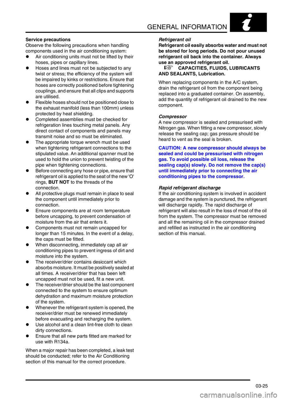
Service precautions
Observe the following precautions when handling
components used in the air conditioning system:
lAir conditioning units must not be lifted by their
hoses, pipes or capillary lines.
lHoses and lines must not be subjected to any
twist or stress; the efficiency of the system will
be impaired by kinks or restrictions. Ensure that
hoses are correctly positioned before tightening
couplings, and ensure that all clips and supports
are utilised.
lFlexible hoses should not be positioned close to
the exhaust manifold (less than 100mm) unless
protected by heat shielding.
lCompleted assemblies must be checked for
refrigeration lines touching metal panels. Any
direct contact of components and panels may
transmit noise and so must be eliminated.
lThe appropriate torque wrench must be used
when tightening refrigerant connections to the
stipulated value. An additional spanner must be
used to hold the union to prevent twisting of the
pipe when tightening connections.
lBefore connecting any hose or pipe, ensure that
refrigerant oil is applied to the seat of the new 'O'
rings, BUT NOT to the threads of the
connection.
lAll protective plugs must remain in place to seal
the component until immediately prior to
connection.
lEnsure components are at room temperature
before uncapping, to prevent condensation of
moisture from the air that enters it.
lComponents must not remain uncapped for
longer than 15 minutes. In the event of a delay,
the caps must be fitted.
lWhen disconnecting, immediately cap all air
conditioning pipes to prevent ingress of dirt and
moisture into the system.
lThe receiver/drier contains desiccant which
absorbs moisture. It must be positively sealed at
all times. A receiver/drier that has been left
uncapped must not be used, fit a new unit.
lThe receiver/drier should be the last component
connected to the system to ensure optimum
dehydration and maximum moisture protection
of the system.
lWhenever the refrigerant system is opened, the
receiver/drier must be renewed immediately
before evacuating and recharging the system.
lUse alcohol and a clean lint-free cloth to clean
dirty connections.
lEnsure that all new parts fitted are marked for
use with R134a.
When a major repair has been completed, a leak test
should be conducted; refer to the Air Conditioning
section of this manual for the correct procedure.Refrigerant oil
Refrigerant oil easily absorbs water and must not
be stored for long periods. Do not pour unused
refrigerant oil back into the container. Always
use an approved refrigerant oil.
+ CAPACITIES, FLUIDS, LUBRICANTS
AND SEALANTS, Lubrication.
When replacing components in the A/C system,
drain the refrigerant oil from the component being
replaced into a graduated container. On assembly,
add the quantity of refrigerant oil drained to the new
component.
Compressor
A new compressor is sealed and pressurised with
Nitrogen gas. When fitting a new compressor, slowly
release the sealing cap; gas pressure should be
heard to vent as the seal is broken.
CAUTION: A new compressor should always be
sealed and could be pressurised with nitrogen
gas. To avoid possible oil loss, release the
sealing cap(s) slowly. Do not remove the cap(s)
until immediately prior to connecting the air
conditioning pipes to the compressor.
Rapid refrigerant discharge
If the air conditioning system is involved in accident
damage and the system is punctured, the refrigerant
will discharge rapidly. The rapid discharge of
refrigerant will also result in the loss of most of the oil
from the system. The compressor must be removed
and all the remaining oil in the compressor drained
and refilled as instructed in the air conditioning
section of this manual.
Page 97 of 1529

TORQUE WRENCH SETTINGS
06-6
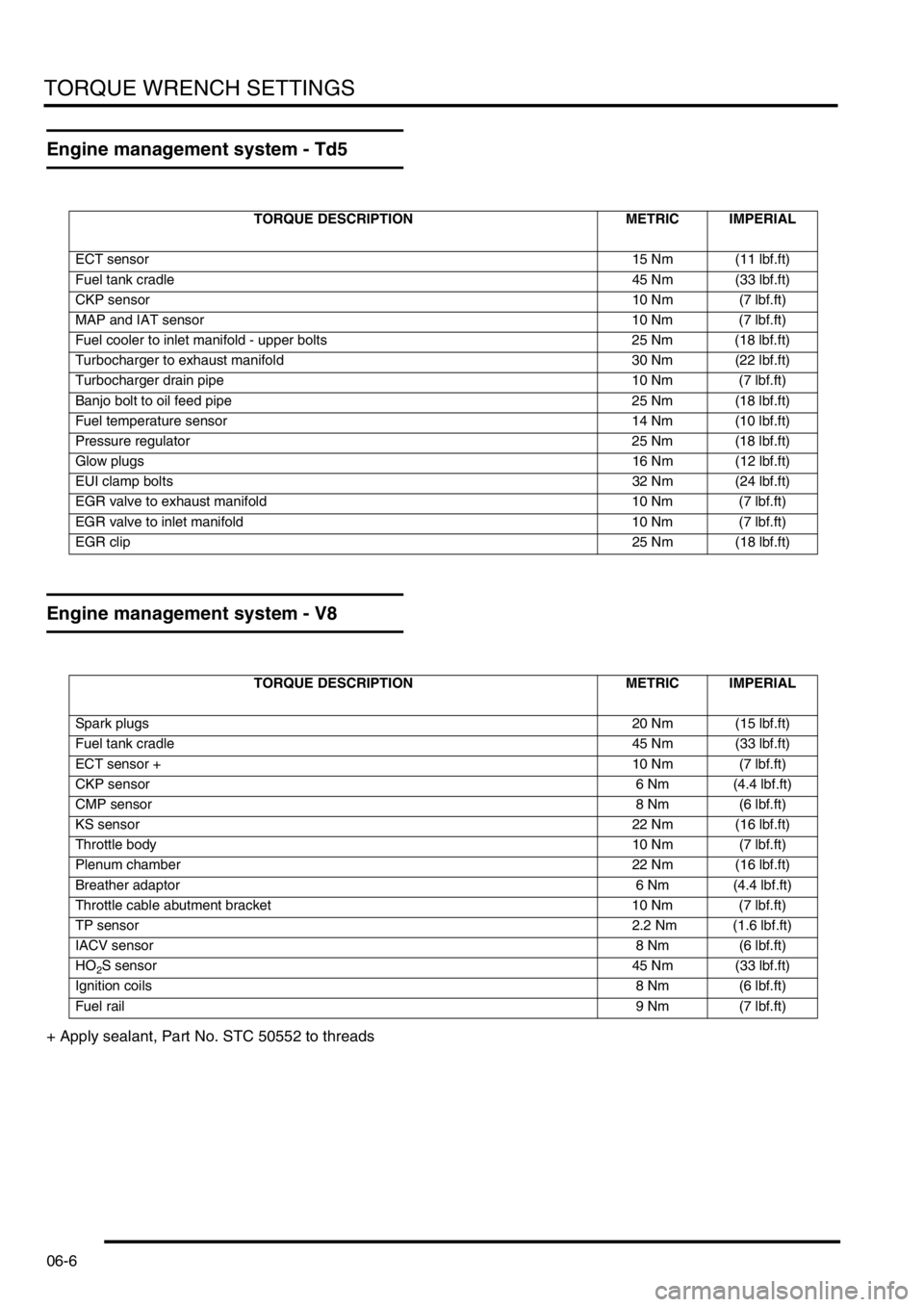
Engine management system - Td5
Engine management system - V8
+ Apply sealant, Part No. STC 50552 to threads
TORQUE DESCRIPTION METRIC IMPERIAL
ECT sensor15 Nm (11 lbf.ft)
Fuel tank cradle45 Nm (33 lbf.ft)
CKP sensor10 Nm (7 lbf.ft)
MAP and IAT sensor 10 Nm (7 lbf.ft)
Fuel cooler to inlet manifold - upper bolts 25 Nm (18 lbf.ft)
Turbocharger to exhaust manifold 30 Nm (22 lbf.ft)
Turbocharger drain pipe 10 Nm (7 lbf.ft)
Banjo bolt to oil feed pipe 25 Nm (18 lbf.ft)
Fuel temperature sensor 14 Nm (10 lbf.ft)
Pressure regulator 25 Nm (18 lbf.ft)
Glow plugs16 Nm (12 lbf.ft)
EUI clamp bolts32 Nm (24 lbf.ft)
EGR valve to exhaust manifold 10 Nm (7 lbf.ft)
EGR valve to inlet manifold 10 Nm (7 lbf.ft)
EGR clip25 Nm (18 lbf.ft)
TORQUE DESCRIPTION METRIC IMPERIAL
Spark plugs20 Nm (15 lbf.ft)
Fuel tank cradle45 Nm (33 lbf.ft)
ECT sensor +10 Nm (7 lbf.ft)
CKP sensor6 Nm (4.4 lbf.ft)
CMP sensor8 Nm (6 lbf.ft)
KS sensor22 Nm (16 lbf.ft)
Throttle body10 Nm (7 lbf.ft)
Plenum chamber22 Nm (16 lbf.ft)
Breather adaptor6 Nm (4.4 lbf.ft)
Throttle cable abutment bracket 10 Nm (7 lbf.ft)
TP sensor 2.2 Nm (1.6 lbf.ft)
IACV sensor8 Nm (6 lbf.ft)
HO
2S sensor45 Nm (33 lbf.ft)
Ignition coils8 Nm (6 lbf.ft)
Fuel rail9 Nm (7 lbf.ft)
Page 102 of 1529

TORQUE WRENCH SETTINGS
06-11
Transfer box - LT230SE
† New nut must be fitted
* New Patchlok nut must be fitted
+ Apply sealant, Part No. STC 50552 to threads
TORQUE DESCRIPTION METRIC IMPERIAL
High/low selector cable 30 Nm (22 lbf.ft)
Bottom cover plate bolts + 25 Nm (18 lbf.ft)
Transfer box to gearbox bolts - Petrol and diesel + 45 Nm (33 lbf.ft)
Rear cover plate stud nut/bolts + 25 Nm (18 lbf.ft)
Differential lock warning lamp switch locknut - Up to 03 MY 11 Nm (8 lbf.ft)
Differential lock warning lamp switches - 03 MY onwards + 25 Nm (18 lbf.ft)
Drive flange nut 148 Nm (109 lbf.ft)
Output shaft housing bolts + 45 Nm (33 lbf.ft)
Oil temperature sensor - If fitted + 25 Nm (18 lbf.ft)
Inhibitor switch to transfer box 26 Nm (19 lbf.ft)
Intermediate shaft nut † 88 Nm (65 lbf.ft)
Intermediate shaft retaining plate bolt + 25 Nm (18 lbf.ft)
Differential bearing retaining nut * 72 Nm (53 lbf.ft)
Output flange nut 162 Nm (119 lbf.ft)
High/Low selector housing bolts + 25 Nm (18 lbf.ft)
Bearing housing/cover bolts + 25 Nm (18 lbf.ft)
Blanking plug + 25 Nm (18 lbf.ft)
High/Low selector warning lamp switch 25 Nm (18 lbf.ft)
Differential lock selector housing bolts + 25 Nm (18 lbf.ft)
Neutral sensor 25 Nm (18 lbf.ft)
Interlock solenoid bolts - Up to 03 Model Year 10 Nm (7 lbf.ft)
Page 119 of 1529

CAPACITIES, FLUIDS, LUBRICANTS AND SEALANTS
09-2
Fluids
Anti-freeze
Use Havoline Extended Life Coolant (XLC), or any
ethylene glycol based anti-freeze (containing no
methanol) with only Organic Acid Technology (OAT)
corrosion inhibitors, to protect the cooling system
CAUTION: No other anti-freeze should be used
with Havoline Extended Life Coolant.
The cooling system should be drained, flushed and
refilled with the correct amount of anti-freeze solution
at the intervals given on the Service Maintenance
Check Sheet.
After filling with anti-freeze solution, attach a warning
label to a prominent position on the vehicle stating
the type of anti-freeze contained in the cooling
system to ensure that the correct type is used for
topping-up.
Brake/Clutch fluid
Use only DOT 4 brake fluid.
PAS fluid
Use Texaco cold climate power assisted steering
fluid PSF 14315.
ACE fluid
Where ambient temperature falls below -20° C (-4°
F), use only Texaco cold climate power assisted
steering fluid PSF 14315. Where ambient
temperature remains above -20° C (-4° F), use either
Texaco cold climate power assisted steering fluid ,
Dexron 11 or Dexron 111 non-synthetic fluid.
Air conditioning
Use only refrigerant R134a.
Refrigerant oil
Use only Nippon Denso ND-oil 8.
Refrigerant oil absorbs water and must not be stored
for long periods. Do not pour unused oil back into the
container.
NOTE: The total quantity of refrigerant oil in the
system is 180 ml.
CAUTION: Do not use any other type of
refrigerant oil.
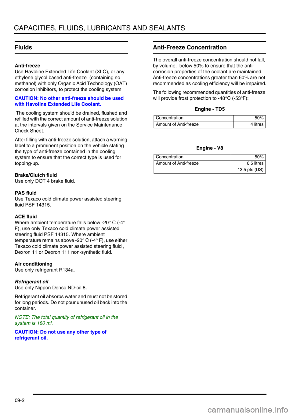
Anti-Freeze Concentration
The overall anti-freeze concentration should not fall,
by volume, below 50% to ensure that the anti-
corrosion properties of the coolant are maintained.
Anti-freeze concentrations greater than 60% are not
recommended as cooling efficiency will be impaired.
The following recommended quantities of anti-freeze
will provide frost protection to -48°C (-53°F):
Engine - TD5
Engine - V8
Concentration 50%
Amount of Anti-freeze 4 litres
Concentration 50%
Amount of Anti-freeze 6.5 litres
13.5 pts (US)
Page 120 of 1529

CAPACITIES, FLUIDS, LUBRICANTS AND SEALANTS
09-3
Lubrication
General
The engine and other lubricating systems are filled
with high-performance lubricants giving prolonged
life.
CAUTION: Always use a high quality oil of the
correct viscosity range in the engine. The use of
oil of the incorrect specification can lead to high
oil and fuel consumption and ultimately to
damaged components.
Oil to the correct specification contains additives
which disperse the corrosive acids formed by
combustion and prevent the formation of sludge
which can block the oil ways. Additional oil additives
should not be used.
Always adhere to the recommended servicing
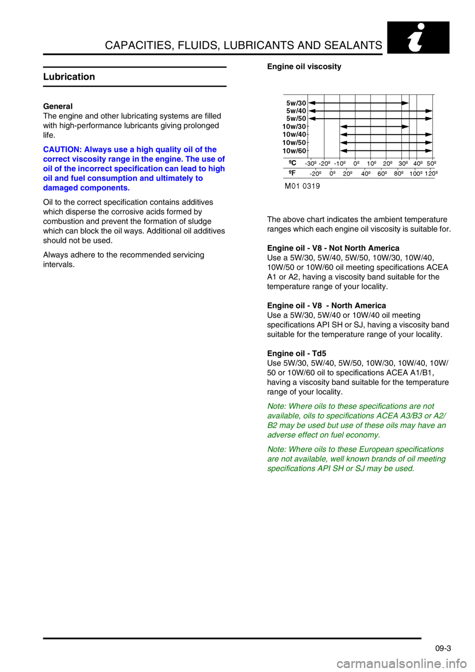
intervals.Engine oil viscosity
The above chart indicates the ambient temperature
ranges which each engine oil viscosity is suitable for.
Engine oil - V8 - Not North America
Use a 5W/30, 5W/40, 5W/50, 10W/30, 10W/40,
10W/50 or 10W/60 oil meeting specifications ACEA
A1 or A2, having a viscosity band suitable for the
temperature range of your locality.
Engine oil - V8 - North America
Use a 5W/30, 5W/40 or 10W/40 oil meeting
specifications API SH or SJ, having a viscosity band
suitable for the temperature range of your locality.
Engine oil - Td5
Use 5W/30, 5W/40, 5W/50, 10W/30, 10W/40, 10W/
50 or 10W/60 oil to specifications ACEA A1/B1,
having a viscosity band suitable for the temperature
range of your locality.
Note: Where oils to these specifications are not
available, oils to specifications ACEA A3/B3 or A2/
B2 may be used but use of these oils may have an
adverse effect on fuel economy.
Note: Where oils to these European specifications
are not available, well known brands of oil meeting
specifications API SH or SJ may be used.
Page 121 of 1529

CAPACITIES, FLUIDS, LUBRICANTS AND SEALANTS
09-4
Gearbox oil
Manual Gearbox: Use Texaco MTF 94 oil for refill
and topping-up.
Automatic Gearbox: Use Texamatic 9226, ATF
Dexron 11D or Dexron 111 for refill and topping-up
Transfer box
Use Texaco Multi-Gear 75W/90R or oil meeting
specification API GL5.
Front and rear axles
Use Texaco Multi-Gear 75W/90R.
Air Conditioning
Use lubricating oil Nippon Denso ND-8.
General Greasing
Use Multipurpose Lithium Base Grease N.L.G.I.
consistency No. 2.
Bonnet latch
Lubricate cable and latch with oil.
Sealants
The following table lists those sealants which are
used during repair / overhaul procedures covered in
this manual; it is essential that the sealant specified
for a particular procedure is used at all times.
Component Application Land Rover
Part No.
Td5 Engine Timing chain fixed
guide Allen screwSTC 50552
Td5 Engine Camshaft cover
gasket joint lineSTC 50550
Td5 Engine Oil pick-up strainer
Torx screwsSTC 50552
Td5 Engine Oil pump drive
sprocket retaining
boltSTC 50552
Td5 Engine Timing chain cover,
crankshaft rear oil
seal and sump
gasket joint linesSTC 50550
Td5 Engine Oil pressure relief
valve plugSTC 50552
Td5 Engine Camshaft carrier to
cylinder headSTC 4600
Td5 Engine Timing cover STC 50550
V8 Engine Sump gasket to
cylinder blockSTC 50550
V8 Engine 'V' grooves at end
of cylinder head -
Inlet manifold
gasketSTC 50550
V8 Engine Cruciform seal
endsSTC 50550
V8 Engine Dipstick tube STC 50554
V8 Engine Timing cover bolts STC 50552
Engine
Management
System - V8Engine coolant
temperature (ECT)
sensor threadsSTC 50552
Manifolds and
Exhaust
System - V8'V' grooves at end
of cylinder head -
Inlet manifold
gasketSTC 50550
Manual
Gearbox -
R380Gear selector
housingSTC 4404
Manual
Gearbox -
R380Selector housing
boltsSTC 50552
Manual
Gearbox -
R380Input shaft oil seal
housingSTC 4404
Manual
Gearbox -
R380Reverse inhibitor
shaft threadsSTC 50552
Page 224 of 1529

ENGINE - V8
OVERHAUL 12-2-69
9.Check overall dimensions of gudgeon pin.
Gudgeon pins are only supplied as an
assembly with replacement pistons.
lGudgeon pin length = 60.00 to 60.50 mm
(2.362 to 2.382 in).
lGudgeon pin diameter = 23.995 to 24.00
mm (0.9446 to 0.9448 in)
10.Measure cylinder bore wear and ovality in two
axis 40 to 50 mm (1.6 to 2 in) from top of bore.
The temperature of piston and cylinder
block must be the same to ensure accurate
measurement. Do not attempt to de-glaze
cylinder bores.
lGrade 'A' pistons: Cylinder bore = 94.00 to
94.015 mm (3.7007 to 3.7013 in).
lGrade 'B' pistons: Cylinder bore = 94.016 to
94.030 mm (3.7014 to 3.7019 in).
lMaximum ovality = 0.013 mm (0.0005 in).
11.Check alignment of connecting rods. Reassembly
1.Pistons have a 5 mm (0.2 in) offset gudgeon pin
which can be identified by an arrow mark on
the piston crown. This arrow must always point
towards the front of the engine.
2.Assemble pistons to connecting rods with
arrow on piston pointing towards domed
shaped boss on connecting rod for RH bank of
cylinders and arrow pointing away from domed
shaped boss for LH bank of cylinders.
3.Clamp hexagon body of tool LRT-12-013 in
vice.
4.Screw large nut back until flush with end of
centre screw.
5.Locate remover/replacer adapter LRT-12-126/
2 with its long spigot inside bore of hexagon
body.
6.Fit parallel sleeve, part of tool LRT-12-013,
ensuring that grooved end is towards open end
of tool LRT-12-013. Position sleeve up to
shoulder of centre screw.
7.Lubricate gudgeon pin and bores of connecting
rod and piston with graphite oil.
8.Locate connecting rod and piston to centre
screw with connecting rod entered on parallel
sleeve, part of LRT-12-013 up to the machined
groove on the sleeve.