brake sensor LAND ROVER DISCOVERY 2002 User Guide
[x] Cancel search | Manufacturer: LAND ROVER, Model Year: 2002, Model line: DISCOVERY, Model: LAND ROVER DISCOVERY 2002Pages: 1672, PDF Size: 46.1 MB
Page 399 of 1672

ENGINE MANAGEMENT SYSTEM - TD5
18-1-6 DESCRIPTION AND OPERATION
Description
General
An engine control module (ECM) controls the five-cylinder direct injection diesel engine, and works on the drive by
wire principle. This means there is no throttle cable, the ECM controls the drivers needs via a signal from the Throttle
Position (TP) sensor on the throttle pedal.
The ECM is a full authoritative diesel specific microprocessor that also incorporates features for cruise control and air
conditioning control. In addition, the ECM supplies output control for the exhaust gas recirculation and turbocharger
boost pressure. The ECM has a self-diagnostic function, which is able to provide backup strategies for most sensor
failures.
The ECM processes information from the following input sources:
lMass air flow sensor.
lAmbient air pressure sensor.
lManifold absolute pressure/inlet air temperature sensor.
lEngine coolant temperature sensor.
lCrankshaft speed and position sensor.
lThrottle position sensor.
lFuel temperature sensor.
lAir conditioning request.
lAir conditioning fan request.
lBrake pedal switch.
lClutch switch.
lCruise control master switch.
lCruise control SET+ switch.
lCruise control RES switch.
lHigh/low ratio switch.
The input from the sensors constantly updates the ECM with the current operating condition of the engine. Once the
ECM has compared current information with stored information within its memory, it can make any adjustment it
requires to the operation of the engine via the following:
lAir conditioning clutch relay.
lAir conditioning cooling fan relay.
lElectronic vacuum regulator solenoid.
lMalfunction indicator lamp.
lFuel pump relay.
lGlow plug warning lamp.
lGlow plugs.
lFuel injectors.
lMain relay.
lTurbocharger wastegate modulator.
lTemperature gauge.
The ECM interfaces with the following:
lElectronic Automatic Transmission (EAT).
lSelf Levelling and Anti-lock Brakes System (SLABS).
lSerial communication link.
lInstrument cluster.
lBody Control Unit (BCU).
Page 402 of 1672

ENGINE MANAGEMENT SYSTEM - TD5
DESCRIPTION AND OPERATION 18-1-9
Connector C0658
Pin No. Input/Output Function Signal type Value Interfaces
B1 Input Earth 1 0 volts 0 volts
B2 Input Earth 4 0 volts 0 volts
B3 Input Supply battery voltage 12 volts 12 volts
B4 Output Cooling fan relay Switch 12-0 volts A/C ECU
B5 Output Fuel pump relay Switch 12-0 volts
B6 Output MIL Switch 12-0 volts Instruments
B7 Output Temperature gauge Digital 0-12 volts Instruments
B8 Not used
B9 Input A/C clutch request Switch 12-0 volts A/C ECU
B10 Input Normally closed brake
switchSwitch 12-0 volts
B11 Input Cruise control SET+ switch Switch 12-0 volts
B12 Input TP sensor 1 Analogue 0- 5 volts
B13 Input Vehicle speed Digital 0-12 volts
B14 Input TP sensor supply 5 volts 5 volts
B15 Input Cruise control master switch Switch 12-0 volts
B16 Input Normally open brake switch Switch 0-12 volts
B17 Input Cruise control RES switch Switch 12-0 volts
B18 Input/Output Serial communication link Digital 0-12 volts All ECU's
B19 Output Tachometer engine speed Digital 0-12 volts Instrument
Cluster
B20 Not used
B21 Output Main relay Switch 0-12 volts
B22 Input Supply battery voltage 12 volts 12 volts
B23 Input A/C fan request Switch 12-0 volts
B24 Input Earth 3 0 volts 0 volt
B25 Input Earth 2 0 volts 0 volts
B26 Input TP sensor earth 0 volts 0 volts
B27 Input Supply 2 12 volts 12 volts
B28 Not used
B29 Output A/C relay Switch 12-0 volts
B30 Output Glow plug warning light Switch 12-0 volts Instrument
Cluster
B31 Not used
B32 Output ABS digital 0-5 volts SLABS
B33 Input Ignition Switch 0-12 volts
B34 Input Security code digital 0-5 volts
B35 Input Clutch switch Switch 12-0 volts
B36 Input TP sensor 2 Analogue 5-0 volts
Page 435 of 1672

ENGINE MANAGEMENT SYSTEM - TD5
18-1-42 DESCRIPTION AND OPERATION
Cruise control resumption
Cruise control can be resumed at the previously set speed, provided the set speed has not been erased from the
ECM's memory as described above.
To resume cruise control operation to the previously set speed, depress the RES switch once when the following
conditions are met:
lA set speed is stored in the ECM.
lVehicle speed is above 22 mph (35 km/h).
lThe brake pedal is not pressed.
lThe clutch pedal is not pressed (manual transmission only).
lThe transmission is not in Park, Reverse or Neutral (automatic transmission only).
The ECM activates the cruise control system at the stored speed.
Accelerating while cruise control is active
There are three ways of increasing vehicle speed when cruise control is active:
lTemporarily increase vehicle speed (e.g. when overtaking another vehicle).
lIncrease vehicle set speed in 1 mph (1.5 km/h) increments.
lIncrease vehicle set speed.
To temporarily increase vehicle speed press the accelerator pedal until the desired speed is reached.
When the accelerator pedal is released, the vehicle coasts back to the set speed. When it reaches the set speed,
cruise control operation continues.
To increase the vehicle set speed in 1 mph (1.5 km/h) increments, tap the SET+ switch. Each tap on the switch
increases vehicle speed.
To increase the vehicle set speed, press and hold the SET+ switch until the desired set speed is reached.
Vehicle set speed will increase if the following conditions are met:
lThe vehicle is under cruise control operation.
lVehicle speed is above 22 mph (35 km/h).
lThe brake pedal is not pressed.
lThe clutch pedal is not pressed (manual transmission only).
lThe transmission is not in Park, Reverse or Neutral (automatic transmission only).
The vehicle responds as follows:
lIf the driver accelerates using the throttle pedal, the ECM increases vehicle speed using the TP sensor signal.
When the driver releases the accelerator pedal, the vehicle returns to the set speed.
lIf the SET+ switch is tapped the stored speed and vehicle speed increases by 1 mph (1.5 km/h) per tap on the
switch.
lIf the driver presses and holds the SET+ switch the vehicle speed will increase and will hold the speed when the
switch is released.
Switching off cruise control
Switching off cruise control allows the driver to regain control of vehicle speed, and erases the set road speed from
the ECM's memory.
To switch off cruise control, press the cruise control master switch to the off position.
When the cruise control master switch is switched off, the ECM deactivates cruise control and the driver regains
control of vehicle speed.
Page 646 of 1672
MANIFOLDS AND EXHAUST SYSTEMS - V8
REPAIRS 30-2-17
Gasket - inlet manifold - upper - Without
Secondary Air Injection
$% 30.15.24
Remove
1.Release fixings and remove battery cover.
2.Disconnect battery earth lead.
3.Remove bonnet.
+ EXTERIOR FITTINGS, REPAIRS,
Bonnet.
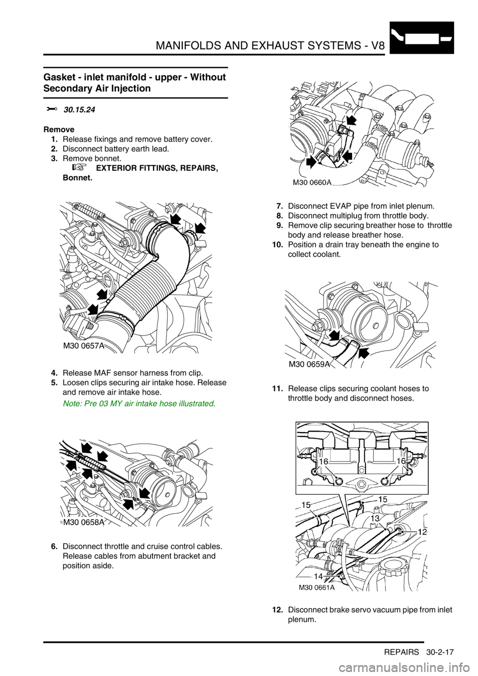
4.Release MAF sensor harness from clip.
5.Loosen clips securing air intake hose. Release
and remove air intake hose.
Note: Pre 03 MY air intake hose illustrated.
6.Disconnect throttle and cruise control cables.
Release cables from abutment bracket and
position aside. 7.Disconnect EVAP pipe from inlet plenum.
8.Disconnect multiplug from throttle body.
9.Remove clip securing breather hose to throttle
body and release breather hose.
10.Position a drain tray beneath the engine to
collect coolant.
11.Release clips securing coolant hoses to
throttle body and disconnect hoses.
12.Disconnect brake servo vacuum pipe from inlet
plenum.
Page 647 of 1672
MANIFOLDS AND EXHAUST SYSTEMS - V8
30-2-18 REPAIRS
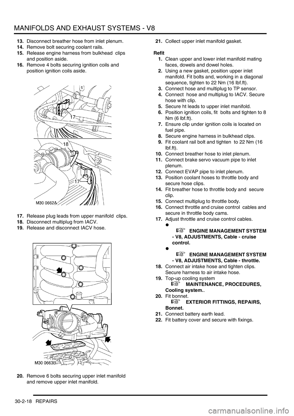
13.Disconnect breather hose from inlet plenum.
14.Remove bolt securing coolant rails.
15.Release engine harness from bulkhead clips
and position aside.
16.Remove 4 bolts securing ignition coils and
position ignition coils aside.
17.Release plug leads from upper manifold clips.
18.Disconnect multiplug from IACV.
19.Release and disconnect IACV hose.
20.Remove 6 bolts securing upper inlet manifold
and remove upper inlet manifold. 21.Collect upper inlet manifold gasket.
Refit
1.Clean upper and lower inlet manifold mating
faces, dowels and dowel holes.
2.Using a new gasket, position upper inlet
manifold. Fit bolts and, working in a diagonal
sequence, tighten to 22 Nm (16 lbf.ft).
3.Connect hose and multiplug to TP sensor.
4.Connect hose and multiplug to IACV. Secure
hose with clip.
5.Secure ht leads to upper inlet manifold.
6.Position ignition coils, fit bolts and tighten to 8
Nm (6 lbf.ft).
7.Ensure clip under ignition coils is located on
fuel pipe.
8.Secure engine harness in bulkhead clips.
9.Fit coolant rail bolt and tighten to 22 Nm (16
lbf.ft).
10.Connect breather hose to inlet plenum.
11.Connect brake servo vacuum pipe to inlet
plenum.
12.Connect EVAP pipe to inlet plenum.
13.Position coolant hoses to throttle body and
secure hose clips.
14.Fit breather hose to throttle body and secure
clip.
15.Connect multiplug to throttle body.
16.Connect throttle and cruise control cables and
secure in throttle body cams.
17.Adjust throttle and cruise control cables.
l
+ ENGINE MANAGEMENT SYSTEM
- V8, ADJUSTMENTS, Cable - cruise
control.
l
+ ENGINE MANAGEMENT SYSTEM
- V8, ADJUSTMENTS, Cable - throttle.
18.Connect air intake hose and tighten clips.
Secure harness to air intake hose.
19.Top-up cooling system
+ MAINTENANCE, PROCEDURES,
Cooling system..
20.Fit bonnet.
+ EXTERIOR FITTINGS, REPAIRS,
Bonnet.
21.Connect battery earth lead.
22.Fit battery cover and secure with fixings.
Page 650 of 1672
MANIFOLDS AND EXHAUST SYSTEMS - V8
REPAIRS 30-2-21
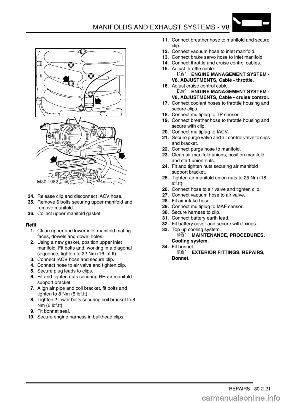
34.Release clip and disconnect IACV hose.
35.Remove 6 bolts securing upper manifold and
remove manifold.
36.Collect upper manifold gasket.
Refit
1.Clean upper and lower inlet manifold mating
faces, dowels and dowel holes.
2.Using a new gasket, position upper inlet
manifold. Fit bolts and, working in a diagonal
sequence, tighten to 22 Nm (16 lbf.ft).
3.Connect IACV hose and secure clip.
4.Connect hose to air valve and tighten clip.
5.Secure plug leads to clips.
6.Fit and tighten nuts securing RH air manifold
support bracket.
7.Align air pipe and coil bracket, fit bolts and
tighten to 8 Nm (6 lbf.ft).
8.Tighten 2 lower bolts securing coil bracket to 8
Nm (6 lbf.ft).
9.Fit bonnet seal.
10.Secure engine harness in bulkhead clips.11.Connect breather hose to manifold and secure
clip.
12.Connect vacuum hose to inlet manifold.
13.Connect brake servo hose to inlet manifold.
14.Connect throttle and cruise control cables.
15.Adjust throttle cable.
+ ENGINE MANAGEMENT SYSTEM -
V8, ADJUSTMENTS, Cable - throttle.
16.Adjust cruise control cable.
+ ENGINE MANAGEMENT SYSTEM -
V8, ADJUSTMENTS, Cable - cruise control.
17.Connect coolant hoses to throttle housing and
secure clips.
18.Connect multiplug to TP sensor.
19.Connect breather hose to throttle housing and
secure with clip.
20.Connect multiplug to IACV.
21.Secure purge valve and air control valve to clips
and bracket.
22.Connect purge hose to manifold.
23.Clean air manifold unions, position manifold
and start union nuts.
24.Fit and tighten nuts securing air manifold
support bracket.
25.Tighten air manifold union nuts to 25 Nm (18
lbf.ft)
26.Connect hose to air valve and tighten clip.
27.Connect vacuum hose to air valve.
28.Fit air intake hose.
29.Connect multiplug to MAF sensor.
30.Secure harness to clip.
31.Connect battery earth lead.
32.Fit battery cover and secure with fixings.
33.Top up cooling system.
+ MAINTENANCE, PROCEDURES,
Cooling system.
34.Fit bonnet.
+ EXTERIOR FITTINGS, REPAIRS,
Bonnet.
Page 698 of 1672
MANUAL GEARBOX - R380
REPAIRS 37-15
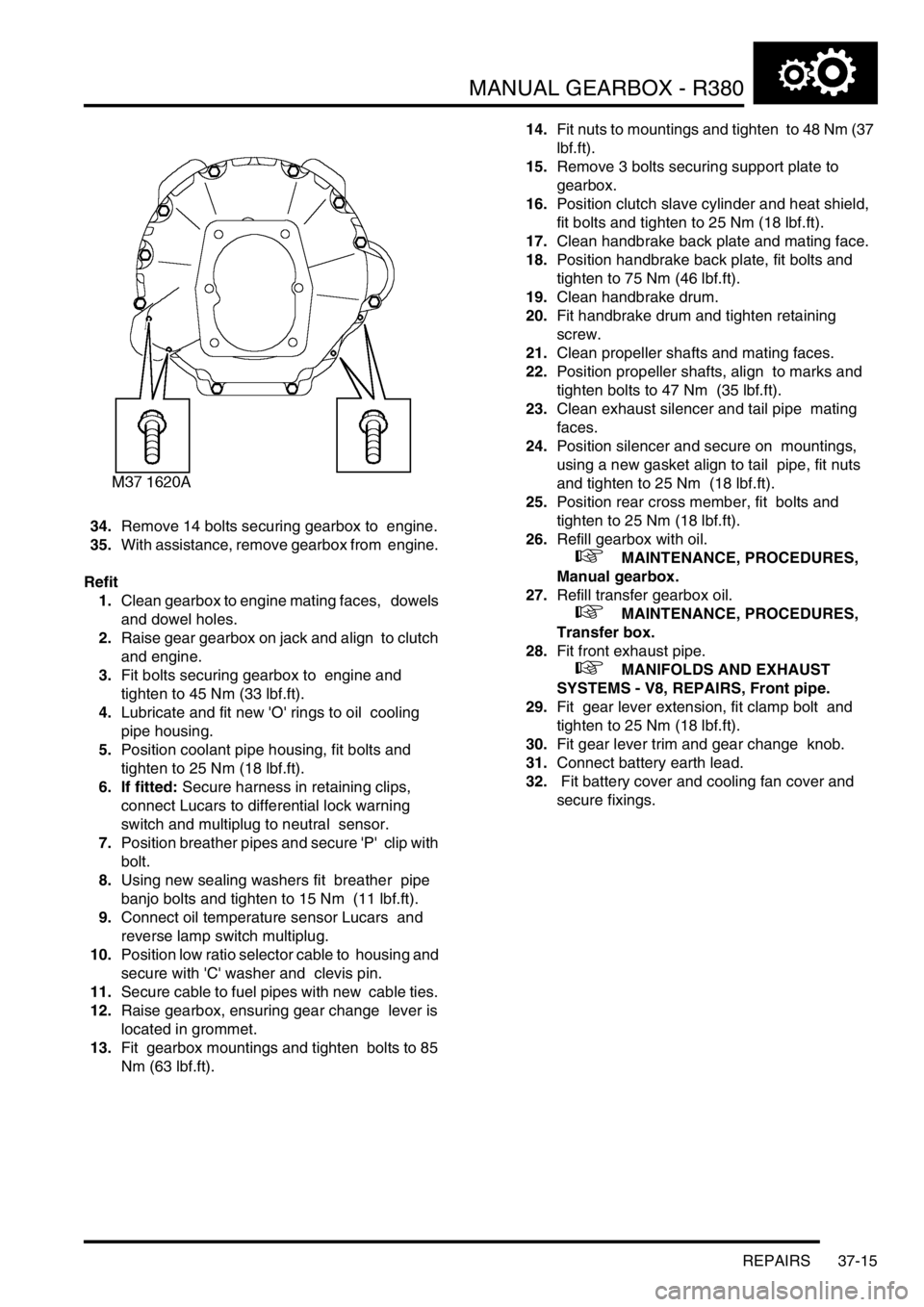
34.Remove 14 bolts securing gearbox to engine.
35.With assistance, remove gearbox from engine.
Refit
1.Clean gearbox to engine mating faces, dowels
and dowel holes.
2.Raise gear gearbox on jack and align to clutch
and engine.
3.Fit bolts securing gearbox to engine and
tighten to 45 Nm (33 lbf.ft).
4.Lubricate and fit new 'O' rings to oil cooling
pipe housing.
5.Position coolant pipe housing, fit bolts and
tighten to 25 Nm (18 lbf.ft).
6. If fitted: Secure harness in retaining clips,
connect Lucars to differential lock warning
switch and multiplug to neutral sensor.
7.Position breather pipes and secure 'P' clip with
bolt.
8.Using new sealing washers fit breather pipe
banjo bolts and tighten to 15 Nm (11 lbf.ft).
9.Connect oil temperature sensor Lucars and
reverse lamp switch multiplug.
10.Position low ratio selector cable to housing and
secure with 'C' washer and clevis pin.
11.Secure cable to fuel pipes with new cable ties.
12.Raise gearbox, ensuring gear change lever is
located in grommet.
13.Fit gearbox mountings and tighten bolts to 85
Nm (63 lbf.ft). 14.Fit nuts to mountings and tighten to 48 Nm (37
lbf.ft).
15.Remove 3 bolts securing support plate to
gearbox.
16.Position clutch slave cylinder and heat shield,
fit bolts and tighten to 25 Nm (18 lbf.ft).
17.Clean handbrake back plate and mating face.
18.Position handbrake back plate, fit bolts and
tighten to 75 Nm (46 lbf.ft).
19.Clean handbrake drum.
20.Fit handbrake drum and tighten retaining
screw.
21.Clean propeller shafts and mating faces.
22.Position propeller shafts, align to marks and
tighten bolts to 47 Nm (35 lbf.ft).
23.Clean exhaust silencer and tail pipe mating
faces.
24.Position silencer and secure on mountings,
using a new gasket align to tail pipe, fit nuts
and tighten to 25 Nm (18 lbf.ft).
25.Position rear cross member, fit bolts and
tighten to 25 Nm (18 lbf.ft).
26.Refill gearbox with oil.
+ MAINTENANCE, PROCEDURES,
Manual gearbox.
27.Refill transfer gearbox oil.
+ MAINTENANCE, PROCEDURES,
Transfer box.
28.Fit front exhaust pipe.
+ MANIFOLDS AND EXHAUST
SYSTEMS - V8, REPAIRS, Front pipe.
29.Fit gear lever extension, fit clamp bolt and
tighten to 25 Nm (18 lbf.ft).
30.Fit gear lever trim and gear change knob.
31.Connect battery earth lead.
32. Fit battery cover and cooling fan cover and
secure fixings.
Page 702 of 1672
MANUAL GEARBOX - R380
REPAIRS 37-19
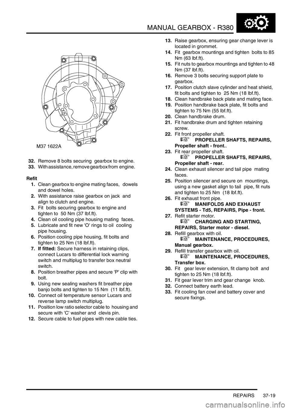
32.Remove 8 bolts securing gearbox to engine.
33.With assistance, remove gearbox from engine.
Refit
1.Clean gearbox to engine mating faces, dowels
and dowel holes.
2.With assistance raise gearbox on jack and
align to clutch and engine.
3.Fit bolts securing gearbox to engine and
tighten to 50 Nm (37 lbf.ft).
4.Clean oil cooling pipe housing mating faces.
5.Lubricate and fit new 'O' rings to oil cooling
pipe housing.
6.Position cooling pipe housing, fit bolts and
tighten to 25 Nm (18 lbf.ft).
7. If fitted: Secure harness in retaining clips,
connect Lucars to differential lock warning
switch and multiplug to transfer box neutral
switch.
8.Position breather pipes and secure 'P' clip with
bolt.
9.Using new sealing washers fit breather pipe
banjo bolts and tighten to 15 Nm (11 lbf.ft).
10.Connect oil temperature sensor Lucars and
reverse lamp switch multiplug.
11.Position low ratio selector cable to housing and
secure with 'C' washer and clevis pin.
12.Secure cable to fuel pipes with new cable ties. 13.Raise gearbox, ensuring gear change lever is
located in grommet.
14.Fit gearbox mountings and tighten bolts to 85
Nm (63 lbf.ft).
15.Fit nuts to gearbox mountings and tighten to 48
Nm (37 lbf.ft).
16.Remove 3 bolts securing support plate to
gearbox.
17.Position clutch slave cylinder and heat shield,
fit bolts and tighten to 25 Nm (18 lbf.ft).
18.Clean handbrake back plate and mating face.
19.Position handbrake back plate, fit bolts and
tighten to 75 Nm (55 lbf.ft).
20.Clean handbrake drum.
21.Fit handbrake drum and tighten retaining
screw.
22.Fit front propeller shaft.
+ PROPELLER SHAFTS, REPAIRS,
Propeller shaft - front..
23.Fit rear propeller shaft.
+ PROPELLER SHAFTS, REPAIRS,
Propeller shaft - rear.
24.Clean exhaust silencer and tail pipe mating
faces.
25.Position silencer and secure on mountings,
using a new gasket align to tail pipe, fit nuts
and tighten to 25 Nm (18 lbf.ft).
26.Fit exhaust front pipe.
+ MANIFOLDS AND EXHAUST
SYSTEMS - Td5, REPAIRS, Pipe - front.
27.Refit starter motor.
+ CHARGING AND STARTING,
REPAIRS, Starter motor - diesel.
28.Refill gearbox with oil.
+ MAINTENANCE, PROCEDURES,
Manual gearbox.
29.Refill transfer gearbox with oil.
+ MAINTENANCE, PROCEDURES,
Transfer box.
30.Fit gear lever extension, fit clamp bolt and
tighten to 25 Nm (18 lbf.ft).
31.Fit gear lever trim and gear change knob.
32.Connect battery earth lead.
33.Fit cooling fan cowl and battery cover and
secure fixings.
Page 762 of 1672
TRANSFER BOX - LT230SE
REPAIRS 41-29
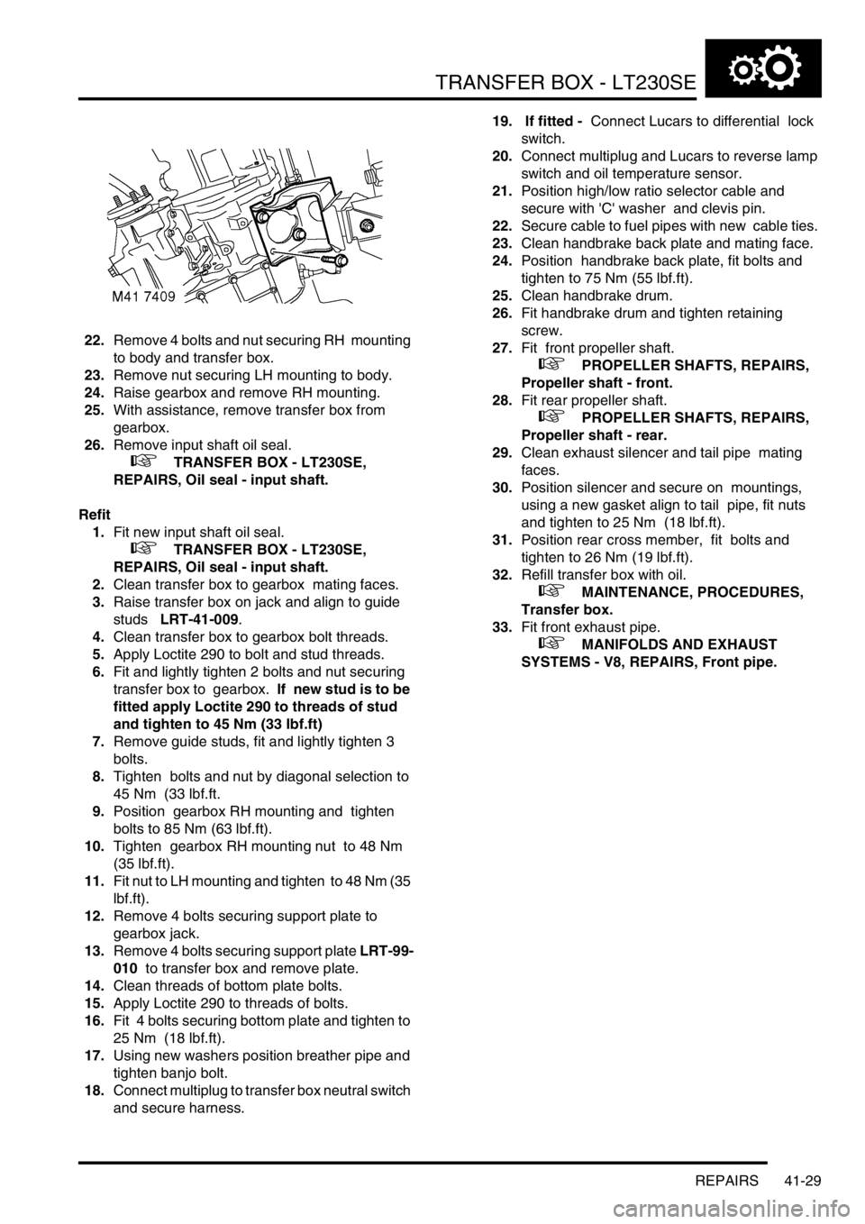
22.Remove 4 bolts and nut securing RH mounting
to body and transfer box.
23.Remove nut securing LH mounting to body.
24.Raise gearbox and remove RH mounting.
25.With assistance, remove transfer box from
gearbox.
26.Remove input shaft oil seal.
+ TRANSFER BOX - LT230SE,
REPAIRS, Oil seal - input shaft.
Refit
1.Fit new input shaft oil seal.
+ TRANSFER BOX - LT230SE,
REPAIRS, Oil seal - input shaft.
2.Clean transfer box to gearbox mating faces.
3.Raise transfer box on jack and align to guide
studs LRT-41-009.
4.Clean transfer box to gearbox bolt threads.
5.Apply Loctite 290 to bolt and stud threads.
6.Fit and lightly tighten 2 bolts and nut securing
transfer box to gearbox. If new stud is to be
fitted apply Loctite 290 to threads of stud
and tighten to 45 Nm (33 lbf.ft)
7.Remove guide studs, fit and lightly tighten 3
bolts.
8.Tighten bolts and nut by diagonal selection to
45 Nm (33 lbf.ft.
9.Position gearbox RH mounting and tighten
bolts to 85 Nm (63 lbf.ft).
10.Tighten gearbox RH mounting nut to 48 Nm
(35 lbf.ft).
11.Fit nut to LH mounting and tighten to 48 Nm (35
lbf.ft).
12.Remove 4 bolts securing support plate to
gearbox jack.
13.Remove 4 bolts securing support plate LRT-99-
010 to transfer box and remove plate.
14.Clean threads of bottom plate bolts.
15.Apply Loctite 290 to threads of bolts.
16.Fit 4 bolts securing bottom plate and tighten to
25 Nm (18 lbf.ft).
17.Using new washers position breather pipe and
tighten banjo bolt.
18.Connect multiplug to transfer box neutral switch
and secure harness. 19. If fitted - Connect Lucars to differential lock
switch.
20.Connect multiplug and Lucars to reverse lamp
switch and oil temperature sensor.
21.Position high/low ratio selector cable and
secure with 'C' washer and clevis pin.
22.Secure cable to fuel pipes with new cable ties.
23.Clean handbrake back plate and mating face.
24.Position handbrake back plate, fit bolts and
tighten to 75 Nm (55 lbf.ft).
25.Clean handbrake drum.
26.Fit handbrake drum and tighten retaining
screw.
27.Fit front propeller shaft.
+ PROPELLER SHAFTS, REPAIRS,
Propeller shaft - front.
28.Fit rear propeller shaft.
+ PROPELLER SHAFTS, REPAIRS,
Propeller shaft - rear.
29.Clean exhaust silencer and tail pipe mating
faces.
30.Position silencer and secure on mountings,
using a new gasket align to tail pipe, fit nuts
and tighten to 25 Nm (18 lbf.ft).
31.Position rear cross member, fit bolts and
tighten to 26 Nm (19 lbf.ft).
32.Refill transfer box with oil.
+ MAINTENANCE, PROCEDURES,
Transfer box.
33.Fit front exhaust pipe.
+ MANIFOLDS AND EXHAUST
SYSTEMS - V8, REPAIRS, Front pipe.
Page 807 of 1672
AUTOMATIC GEARBOX - ZF4HP22 - 24
44-10 DESCRIPTION AND OPERATION
The lock-up and brake clutches are operated by pressurised transmission fluid from the valve block in the sump. A
manual valve and four solenoid valves, also known as Motorised Valves (MV), control the supply of pressurised
transmission fluid from the valve block:
lThe manual valve controls the supply in P, R, N and D.
lSolenoid valves MV 1 and MV 2 control the supplies that operate the brake clutches for shift control.
lSolenoid valve MV 3 controls the supply that operates the lock-up clutch.
lSolenoid valve MV 4 modulates the pressure of the supplies to the brake clutches, to control shift quality.
Operation of the manual valve is controlled by the selector lever assembly. In the gearbox, a selector shaft engages
with the manual valve. The selector shaft is connected to the selector lever assembly via the selector cable and a
selector lever on the left side of the gearbox. The selector shaft also operates a mechanism that locks the output shaft
when P is selected.
Operation of the solenoid valves is controlled by the EAT ECU.
An output shaft speed sensor in the gearbox housing outputs a signal to the EAT ECU. The EAT ECU compares
output shaft speed with engine speed to determine the engaged gear, and output shaft speed with vehicle speed to
confirm the range selected on the transfer box.
A bayonet lock electrical connector in the gearbox casing, to the rear of the selector lever, connects the solenoid
valves and the output shaft speed sensor to the vehicle wiring.
A pressed steel sump encloses the valve block and collects transmission fluid draining from the gearbox housing. A
suction pipe and filter on the underside of the valve block connect to the inlet side of the fluid pump. A magnet is
installed in the sump to collect any magnetic particles that may be present. A level plug and a drain plug are installed
in the sump for servicing.
Rear extension housing
The rear extension housing provides the interface between the gearbox housing and the transfer box. A splined
extension shaft, secured to the gearbox output shaft by a bolt, transmits the drive from the gearbox to the transfer
box. A seal in the rear of the housing prevents leakage past the extension shaft. A breather pipe, attached to the left
side of the rear extension housing, ventilates the interior of the gearbox and rear extension housings to atmosphere.
The open end of the breather pipe is located in the engine compartment at the right front corner of the engine sump
on gearboxes fitted to early vehicles and is clipped to the top of the gearbox on later vehicles.
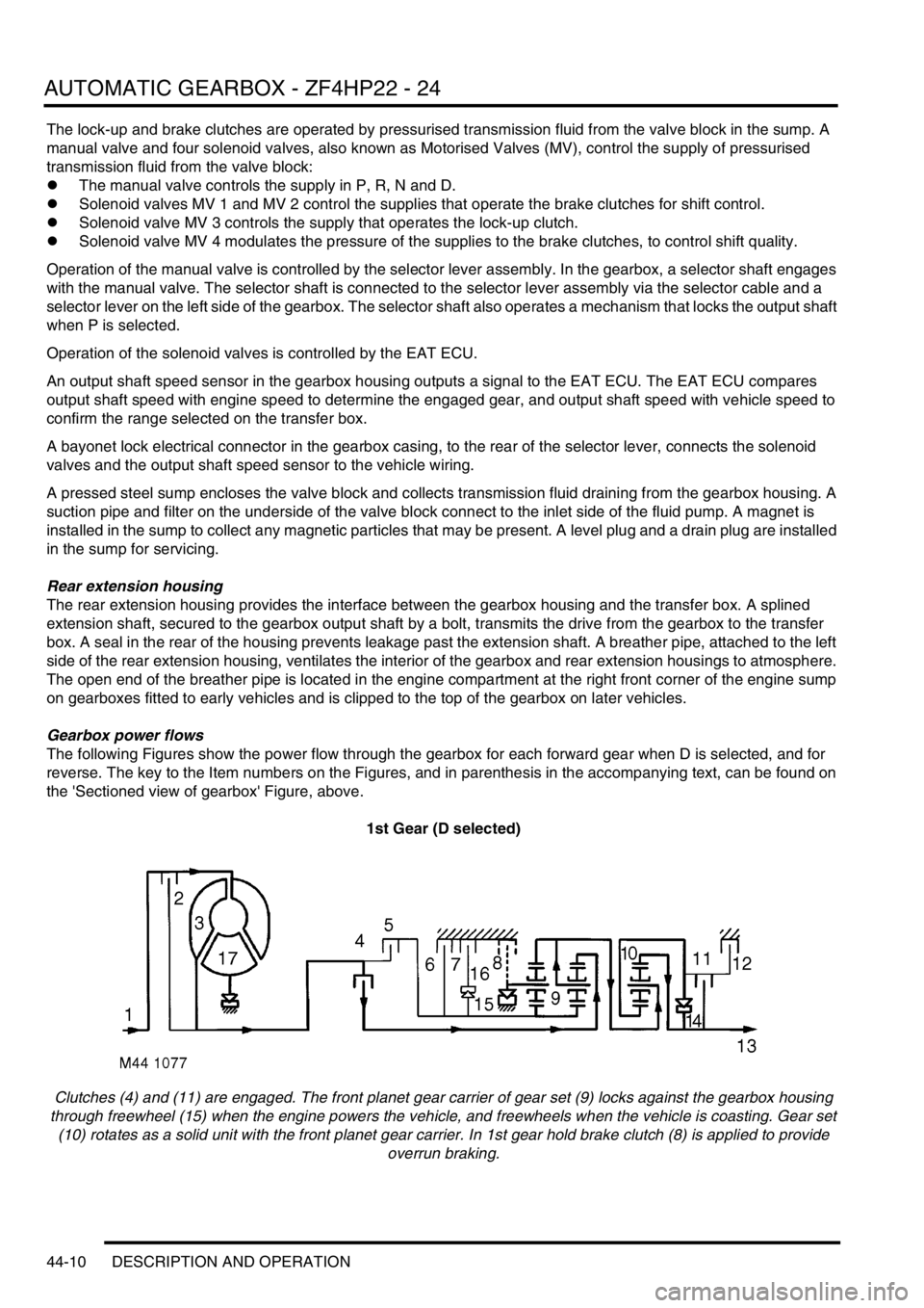
Gearbox power flows
The following Figures show the power flow through the gearbox for each forward gear when D is selected, and for
reverse. The key to the Item numbers on the Figures, and in parenthesis in the accompanying text, can be found on
the 'Sectioned view of gearbox' Figure, above.
1st Gear (D selected)
Clutches (4) and (11) are engaged. The front planet gear carrier of gear set (9) locks against the gearbox housing
through freewheel (15) when the engine powers the vehicle, and freewheels when the vehicle is coasting. Gear set
(10) rotates as a solid unit with the front planet gear carrier. In 1st gear hold brake clutch (8) is applied to provide
overrun braking.