brake sensor LAND ROVER DISCOVERY 2002 Workshop Manual
[x] Cancel search | Manufacturer: LAND ROVER, Model Year: 2002, Model line: DISCOVERY, Model: LAND ROVER DISCOVERY 2002Pages: 1672, PDF Size: 46.1 MB
Page 6 of 1672

CONTENTS
CONTENTS 3
Alarm handset battery ..................................................................................................................... 10-6
Road wheels ................................................................................................................................... 10-7
Tyres .............................................................................................................................................. 10-7
Brake pads, discs and calipers ....................................................................................................... 10-7
Road wheel speed sensors ............................................................................................................. 10-7
Brake fluid ....................................................................................................................................... 10-8
Fuel filter - diesel engine ................................................................................................................. 10-8
Fuel filter sedimenter ...................................................................................................................... 10-8
Road wheels ................................................................................................................................... 10-8
Radiator/Intercooler ........................................................................................................................ 10-8
Ambient air Temperature and pressure sensor .............................................................................. 10-8
Doors, bonnet and fuel filler flap ..................................................................................................... 10-9
Air suspension intake filter .............................................................................................................. 10-9
Anti-freeze....................................................................................................................................... 10-9
Cooling system ............................................................................................................................... 10-9
Spark plugs - V8 engine.................................................................................................................. 10-10
Air cleaner - V8 engine ................................................................................................................... 10-11
Air cleaner and dump valve - diesel engine .................................................................................... 10-11
Auxiliary drive belt ........................................................................................................................... 10-11
Auxiliary drive belt - V8 engine ....................................................................................................... 10-12
Auxiliary drive belt - diesel engine .................................................................................................. 10-12
Fluid reservoirs ............................................................................................................................... 10-12
Steering box .................................................................................................................................... 10-13
Battery ............................................................................................................................................. 10-13
Intercooler - diesel engine............................................................................................................... 10-14
Engine oil - V8 engine ..................................................................................................................... 10-14
Engine oil - diesel engine ................................................................................................................ 10-14
Centrifuge rotor – diesel engine ...................................................................................................... 10-15
Engine oil filter - diesel engine ........................................................................................................ 10-15
Engine oil filter – V8 engine ............................................................................................................ 10-15
Manual gearbox .............................................................................................................................. 10-16
Automatic gearbox ......................................................................................................................... 10-17
Transfer box .................................................................................................................................... 10-18
Front and rear axle .......................................................................................................................... 10-19
Propeller shafts ............................................................................................................................... 10-19
Anti-roll bar links ............................................................................................................................. 10-20
ACE actuators ................................................................................................................................. 10-21
ACE filter ......................................................................................................................................... 10-21
Brake hose, brake, fuel, ACE, clutch pipes and unions/electrical harnesses ................................ 10-22
Engine, gearbox, transfer box and axles ........................................................................................ 10-23
Exhaust system............................................................................................................................... 10-23
Steering box and front suspension ................................................................................................. 10-23
Steering rod ball joints ................................................................................................................... 10-25
Dampers and SLS height sensors .................................................................................................. 10-25
Front and rear axle suspension links .............................................................................................. 10-26
Towing bracket................................................................................................................................ 10-27
Engine mountings - V8 engine ........................................................................................................ 10-27
Road/roller test................................................................................................................................ 10-28
ENGINE - Td5 ........................................................................................... 12-1-1
DESCRIPTION AND OPERATION
Td5 Engine...................................................................................................................................... 12-1-1
Cylinder block components ............................................................................................................. 12-1-2
Page 18 of 1672

CONTENTS
CONTENTS 15
Bushes - radius arm ...................................................................................................................... 60-39
ECU - ACE ..................................................................................................................................... 60-40
Accelerometer - ACE - upper ........................................................................................................ 60-41
Accelerometer - ACE - lower ........................................................................................................ 60-42
Pump - ACE - V8 ............................................................................................................................ 60-42
Pump - ACE - diesel ....................................................................................................................... 60-44
Valve block - ACE ......................................................................................................................... 60-46
Filter - high pressure - ACE .......................................................................................................... 60-48
Pressure transducer - ACE ........................................................................................................... 60-49
Solenoid - pressure control valve - ACE ....................................................................................... 60-50
Solenoid - directional control valve - ACE ..................................................................................... 60-51
Pipe assembly - valve block to front actuator - ACE ...................................................................... 60-51
Pipe assembly - pump or reservoir to valve block - ACE - V8 ....................................................... 60-54
Pipe assembly - pump or reservoir to valve block - ACE - diesel .................................................. 60-57
Pipe assembly - valve block to rear actuator - ACE ........................................................................ 60-61
Actuator - front - ACE .................................................................................................................... 60-63
Bushes - front long arm - ACE ........................................................................................................ 60-65
REAR SUSPENSION ................................................................................ 64-1
DESCRIPTION AND OPERATION
Rear suspension component layout (vehicles with SLS) ............................................................... 64-2
Rear suspension component layout (vehicles without SLS) .......................................................... 64-3
Rear suspension components ........................................................................................................ 64-4
Description ...................................................................................................................................... 64-6
DESCRIPTION AND OPERATION
SLS component layout .................................................................................................................... 64-9
SLS system control diagram ........................................................................................................... 64-10
Description - SLS ............................................................................................................................ 64-12
Operation ........................................................................................................................................ 64-20
ADJUSTMENTS
SLS calibration blocks..................................................................................................................... 64-23
REPAIRS
Wheel hub ....................................................................................................................................... 64-25
Road spring - rear ........................................................................................................................... 64-27
Air spring - SLS ............................................................................................................................... 64-28
Damper - rear ................................................................................................................................ 64-29
Bushes - radius arm ...................................................................................................................... 64-29
Bushes - Watts linkage ................................................................................................................. 64-31
Sensor - height - SLS...................................................................................................................... 64-32
Compressor unit - air - SLS ............................................................................................................ 64-32
Filter - intake - SLS ......................................................................................................................... 64-34
Switch - ride height ......................................................................................................................... 64-34
Air valve - SLS ................................................................................................................................ 64-35
Actuator - rear - ACE ...................................................................................................................... 64-36
Bushes - rear long arm - ACE ......................................................................................................... 64-38
BRAKES ................................................................................................... 70-1
DESCRIPTION AND OPERATION
Page 19 of 1672

CONTENTS
16 CONTENTS
Brake system control component layout ......................................................................................... 70-1
Brake system control diagram ........................................................................................................ 70-2
Brake system hydraulic component layout ..................................................................................... 70-4
Description ...................................................................................................................................... 70-5
Operation ........................................................................................................................................ 70-20
DESCRIPTION AND OPERATION
Handbrake component layout ......................................................................................................... 70-25
Description ...................................................................................................................................... 70-26
ADJUSTMENTS
Handbrake .................................................................................................................................... 70-29
Brake system bleeding .................................................................................................................. 70-30
REPAIRS
Brake disc - front .......................................................................................................................... 70-33
Brake disc - rear ........................................................................................................................... 70-34
Master cylinder - brake ................................................................................................................. 70-35
Cable - handbrake ........................................................................................................................ 70-36
Switch - brake light ....................................................................................................................... 70-37
Brake pads - front ......................................................................................................................... 70-37
Brake pads - rear .......................................................................................................................... 70-38
Brake shoes - handbrake................................................................................................................ 70-39
Servo - brake .................................................................................................................................. 70-41
Vacuum pump - servo..................................................................................................................... 70-42
Housing - caliper - front ................................................................................................................ 70-43
Housing - caliper - rear ................................................................................................................. 70-44
ECU - Self levelling and anti locking brakes (SLABS) ................................................................. 70-45
Sensor – ABS – front ..................................................................................................................... 70-46
Sensor – ABS – rear ....................................................................................................................... 70-47
Modulator unit - ABS ...................................................................................................................... 70-47
Switch - Hill descent control............................................................................................................ 70-48
Switch - handbrake ....................................................................................................................... 70-49
RESTRAINT SYSTEMS ............................................................................ 75-1
DESCRIPTION AND OPERATION
SRS component layout ................................................................................................................... 75-1
SRS block diagram ......................................................................................................................... 75-2
Description - SRS ........................................................................................................................... 75-3
Operation - SRS ............................................................................................................................. 75-9
DESCRIPTION AND OPERATION
Description - seat belts ................................................................................................................... 75-11
REPAIRS
Seat belt - front .............................................................................................................................. 75-13
Seat belt - rear - centre ................................................................................................................. 75-13
Seat belt - rear - side .................................................................................................................... 75-15
Mounting - seat belt - 'B' post ...................................................................................................... 75-16
Seat belts - third row ....................................................................................................................... 75-17
Pre-tensioner - front seat belt ....................................................................................................... 75-18
Airbag module - drivers .................................................................................................................. 75-18
Airbag module - passenger ........................................................................................................... 75-19
DCU ................................................................................................................................................ 75-20
Rotary coupler ................................................................................................................................ 75-21
Airbag deployment tool - self test ................................................................................................... 75-22
Airbag module - drivers - deployment ............................................................................................. 75-23
Page 32 of 1672

INTRODUCTION
01-3
Abbreviations and Symbols
A Amperes
AAP Ambient Air Pressure
AAT Ambient Air Temperature
ABDC After Bottom Dead Centre
ABS Anti-Lock Brake System
ABS / TC Anti-lock Brake System / Traction
Control
ac Alternating current
A/C Air Conditioning
ACE Active Cornering Enhancement
ACEA Association of Constructors of
European Automobiles
AFR Air Fuel Ratio
AP Ambient Pressure
ASC Anti-shunt Control
ATC Air Temperature Control
ATDC After Top Dead Centre
AUX Auxiliary
AVC Automatic Volume Control
BBDC Before Bottom Dead Centre
BBUS Battery Backed Up Sounder
BCU Body Control Unit
BDC Bottom Dead Centre
bhp Brake Horse Power
BP Boost Pressure
BPP Brake Pedal Position
BS British Standard
BTDC Before Top Dead Centre
BWD Backward
C Celsius
CAN Controller Area Network
CD Compact Disc
CDC Centre Differential Control
CDL Central Door Locking
CD - ROM Compact Disc - Read Only
Memory
CFC Chlorofluorocarbon
CHMSL Centre High Mounted Stop Lamp
CKP Crankshaft Position
CLV Calculated Load Value
cm Centimetre
cm
2Square centimetre
cm3Cubic centimetre
CMP Camshaft Position
CPP Clutch Pedal Position
CO Carbon Monoxide
CO
2Carbon Dioxide
COB Clear Over Base
CR Common Rail
CVS Canister Vent Solenoid
dB Decibels
DDM Driver's Door Module
deg. Degree, angle or temperature
DI Direct Injection
dia. DiameterDIN Deutsche Industrie Normen
(German Industrial Standards)
dc Direct current
DCV Directional Control Valve
DOHC Double Overhead Camshaft
DSP Digital Signal Processing
DTI Dial Test Indicator
DMF Dual Mass Flywheel
DVD Digital Versatile Disc
EACV Electronic Air Control Valve
EAT Electronic Automatic
Transmission
EBD Electronic Brake pressure
Distribution
ECD European Community Directive
ECM Engine Control Module
ECT Engine Coolant Temperature
ECU Electronic Control Unit
EDC Electronic Diesel Control
EEPROM Electronic Erasable
Programmable Read Only
Memory
EGR Exhaust Gas Recirculation
EKA Emergency Key Access
ELR Emergency Locking Retractor
EN European Norm
EOBD European On Board Diagnostics
EON Enhanced Other Network
ERL Electrical Reference Library
ETC Electronic Traction Control
EUI Electronic Unit Injector
EVAP Evaporative Emission
EVR Electronic Vacuum Regulator
F Fahrenheit
ft. Feet
FBH Fuel Burning Heater
FET Field Effect Transistor
FIP Fuel Injection Pump
FTC Fast Throttle Control
FWD Forward
> Greater than
g Gramme or Gravity
gal. Gallons
GMT Greenwich Mean Time
GPS Global Positioning System
hHour
hc High compression
HC Hydro Carbons
HDC Hill Descent Control
HDOP Height Dilation Of Precision
HDPE High Density Polyethylene
HFS Heated Front Screen
Hg Mercury
HO
2S Heated Oxygen Sensor
HMW High Molecular Weight
Page 33 of 1672

INTRODUCTION
01-4
HRW Heated Rear Window
HSLA High Strength Low Alloy
ht/HT High tension
IACV Idle Air Control Valve
IAT Intake Air Temperature
ICE In-Car Entertainment
i.dia. Internal diameter
IDM Intelligent Driver Module
IF Intermediate Frequency
in
3Cubic inch
ILT Inlet Throttle
IPW Injector Pulse Width
ISO International Organisation for
Standardisation
ITS Inflatable Tubular Structure
k Thousand
kg Kilogramme
kg/h Kilogrammes per hour
km Kilometre
km/h Kilometres per hour
kPa KiloPascal
KS Knock Sensor
lb(s) Pounds
lbf Pounds force
lbf.in Pounds force inches
lbf/in
2Pounds per square inch
lbf.ft Pounds force feet
λLambda
lc Low compression
LCD Liquid Crystal Display
LED Light Emitting Diode
LEV Low Emission Vehicle
LH Left-Hand
LHD Left-Hand Drive
LSM Light Switch Module
LVS Liquid Vapour Separator
mMetre
µMicro
MAF Mass Air Flow
MAP Manifold Absolute Pressure
MET Mechanical, Electrical and Trim
MFU Multi-Function Unit
MFL Multi-Function Logic
max. Maximum
MEMS Modular Engine Management
System
MIG Metal/Inert Gas
MIL Malfunction Indicator Lamp
MPa MegaPascal
MOSFET Metal Oxide Semiconductor Field
Effect Transistor
min. Minimum
- Minus (tolerance)
' Minute (angle)
mm Millimetre
mph Miles per hour MPi Multi-Point injection
MV Motorised Valve
MY Model Year
NAS North American Specification
(-) Negative (electrical)
Nm Newton metre
No. Number
NO
2Nitrogen Dioxide
NO
xOxides of Nitrogen
NTC Negative Temperature
Coefficient
NRV Non Return Valve
OBD On Board Diagnostics
OBM On Board Monitoring
o.dia. Outside diameter
OAT Organic Acid Technology
ORM Off-road Mode
ΩOhm
PAS Power Assisted Steering
PCB Printed Circuit Board
PCV Positive Crankcase Ventilation
PDC Parking Distance Control
PDOP Position Dilation Of Precision
PI Programme Information
PPS Pulse Per Second
PS Programme Service
psi Pounds per square inch
pts. Pints
% Percentage
+ Plus (tolerance) or Positive
(electrical)
±Plus or minus (tolerance)
PTC Positive Temperature Coefficient
PTFE Polytetrafluorethylene
PVC Polyvinyl chloride
PWM Pulse Width Modulation
RDS Radio Data Service
rRadius
:Ratio
ref Reference
REG Regionalisation
RES Rover Engineering Standards
rev/min Revolutions per minute
RF Radio Frequency
RGB Red / Green / Blue
RH Right-Hand
RHD Right-Hand Drive
ROM Read Only Memory
RON Research Octane Number
ROV Roll Over Valve
ROW Rest Of World
SAE Society of Automotive Engineers
SAI Secondary Air Injection
" Second (angle)
SLABS Self Levelling and Anti-Lock
Brake System
SLS Self Levelling Suspension
SOHC Single Overhead Camshaft
Page 97 of 1672

TORQUE WRENCH SETTINGS
06-12
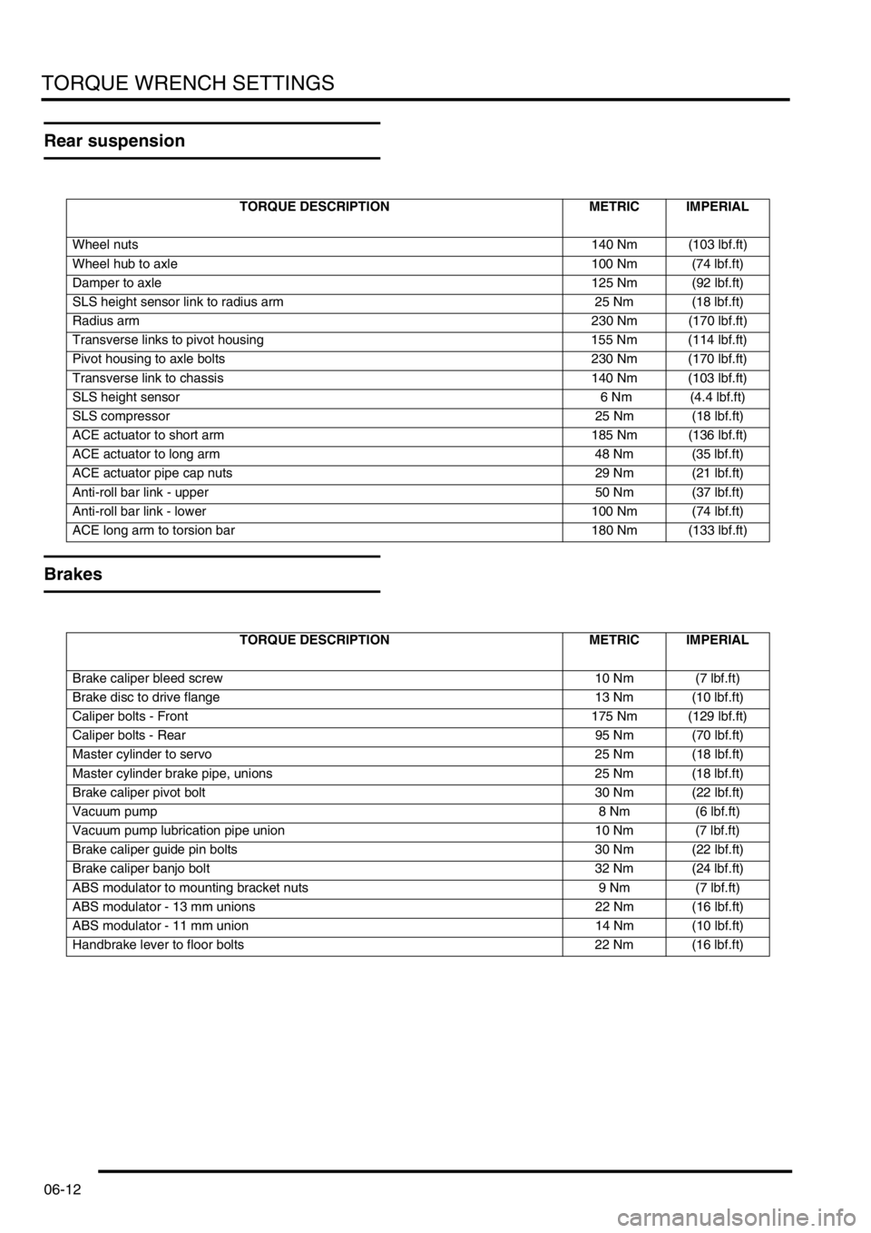
Rear suspension
Brakes
TORQUE DESCRIPTION METRIC IMPERIAL
Wheel nuts140 Nm (103 lbf.ft)
Wheel hub to axle 100 Nm (74 lbf.ft)
Damper to axle125 Nm (92 lbf.ft)
SLS height sensor link to radius arm 25 Nm (18 lbf.ft)
Radius arm230 Nm (170 lbf.ft)
Transverse links to pivot housing 155 Nm (114 lbf.ft)
Pivot housing to axle bolts 230 Nm (170 lbf.ft)
Transverse link to chassis 140 Nm (103 lbf.ft)
SLS height sensor 6 Nm (4.4 lbf.ft)
SLS compressor25 Nm (18 lbf.ft)
ACE actuator to short arm 185 Nm (136 lbf.ft)
ACE actuator to long arm 48 Nm (35 lbf.ft)
ACE actuator pipe cap nuts 29 Nm (21 lbf.ft)
Anti-roll bar link - upper 50 Nm (37 lbf.ft)
Anti-roll bar link - lower 100 Nm (74 lbf.ft)
ACE long arm to torsion bar 180 Nm (133 lbf.ft)
TORQUE DESCRIPTION METRIC IMPERIAL
Brake caliper bleed screw 10 Nm (7 lbf.ft)
Brake disc to drive flange 13 Nm (10 lbf.ft)
Caliper bolts - Front 175 Nm (129 lbf.ft)
Caliper bolts - Rear 95 Nm (70 lbf.ft)
Master cylinder to servo 25 Nm (18 lbf.ft)
Master cylinder brake pipe, unions 25 Nm (18 lbf.ft)
Brake caliper pivot bolt 30 Nm (22 lbf.ft)
Vacuum pump8 Nm (6 lbf.ft)
Vacuum pump lubrication pipe union 10 Nm (7 lbf.ft)
Brake caliper guide pin bolts 30 Nm (22 lbf.ft)
Brake caliper banjo bolt 32 Nm (24 lbf.ft)
ABS modulator to mounting bracket nuts 9 Nm (7 lbf.ft)
ABS modulator - 13 mm unions 22 Nm (16 lbf.ft)
ABS modulator - 11 mm union 14 Nm (10 lbf.ft)
Handbrake lever to floor bolts 22 Nm (16 lbf.ft)
Page 116 of 1672

MAINTENANCE
PROCEDURES 10-7
Road wheels
Remove
1.Mark the wheel to stud relationship to ensure
that the wheels are refitted in the same
position.
2.Loosen wheel nuts. Raise the vehicle to a
wheel-free condition and remove the wheel
nuts.
Tyres
Check
1.Check tyres for compliance with manufacturer's
specification; visually for cuts, lumps, bulges,
uneven tread wear and depth.
2.Check tyre pressures, condition and tread
depth. Measure the tread depth across the
width of the tyre and around the circumference.
Brake pads, discs and calipers
Check
1. Check front and rear brake pads for wear,
ensure all pads are wearing evenly.
2.Check brake discs for signs of cracking,
excessive scoring or oil contamination.
3.Check calipers for signs of fluid leaks.
4.Clean excessive deposits of brake dust from
pads, calipers and disc shields using brake
cleaner.
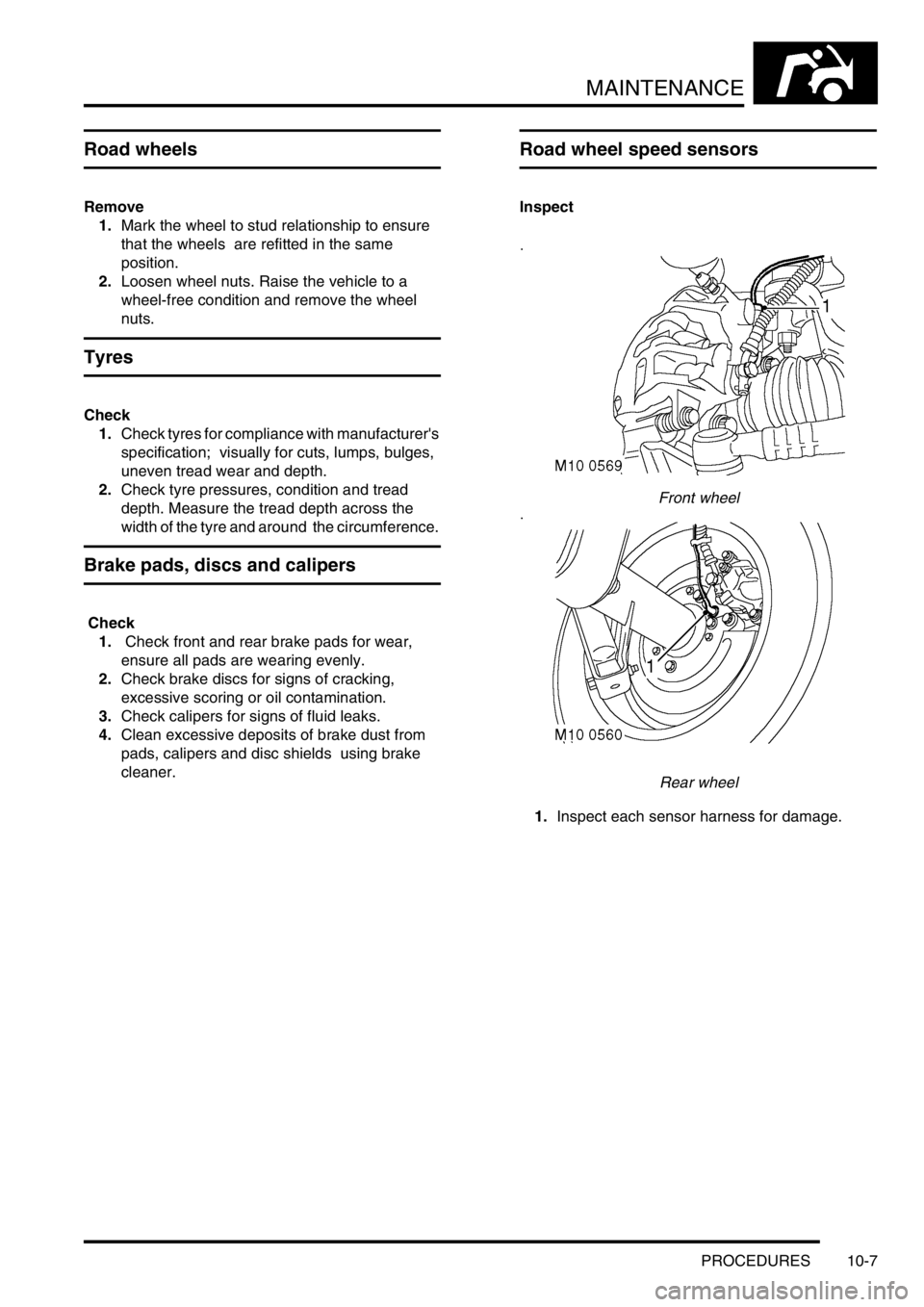
Road wheel speed sensors
Inspect
Front wheel
Rear wheel
1.Inspect each sensor harness for damage.
Page 117 of 1672

MAINTENANCE
10-8 PROCEDURES
Brake fluid
Replace
1.Replace brake fluid.
+ BRAKES, ADJUSTMENTS, Brake
system bleeding.
Fuel filter - diesel engine
Replace
1.Replace filter element.
+ ENGINE MANAGEMENT SYSTEM -
Td5, REPAIRS, Element - fuel filter.
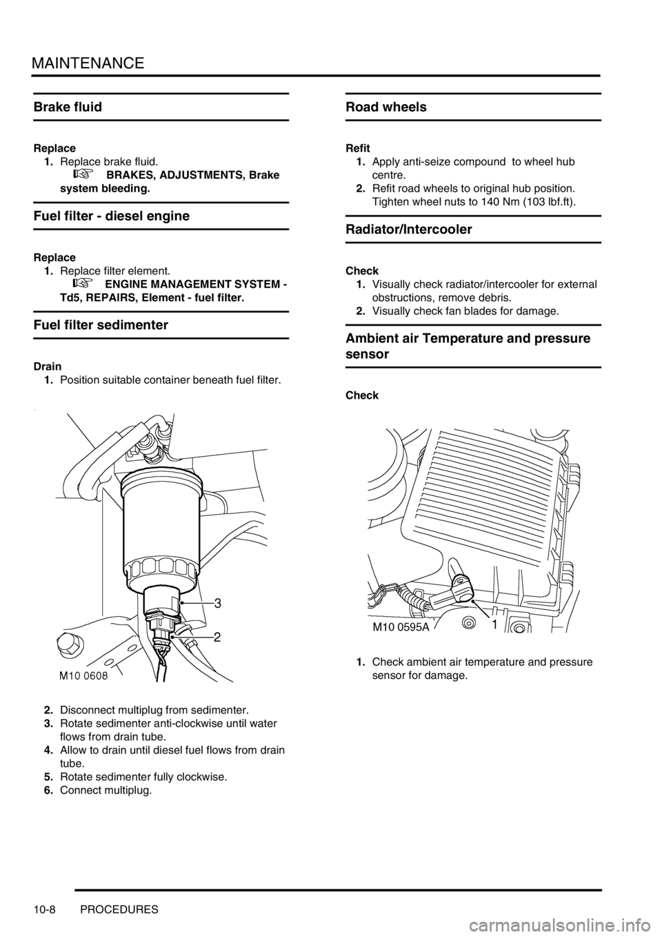
Fuel filter sedimenter
Drain
1.Position suitable container beneath fuel filter.
2.Disconnect multiplug from sedimenter.
3.Rotate sedimenter anti-clockwise until water
flows from drain tube.
4.Allow to drain until diesel fuel flows from drain
tube.
5.Rotate sedimenter fully clockwise.
6.Connect multiplug.
Road wheels
Refit
1.Apply anti-seize compound to wheel hub
centre.
2.Refit road wheels to original hub position.
Tighten wheel nuts to 140 Nm (103 lbf.ft).
Radiator/Intercooler
Check
1.Visually check radiator/intercooler for external
obstructions, remove debris.
2.Visually check fan blades for damage.
Ambient air Temperature and pressure
sensor
Check
1.Check ambient air temperature and pressure
sensor for damage.
Page 395 of 1672

ENGINE MANAGEMENT SYSTEM - TD5
18-1-2 DESCRIPTION AND OPERATION
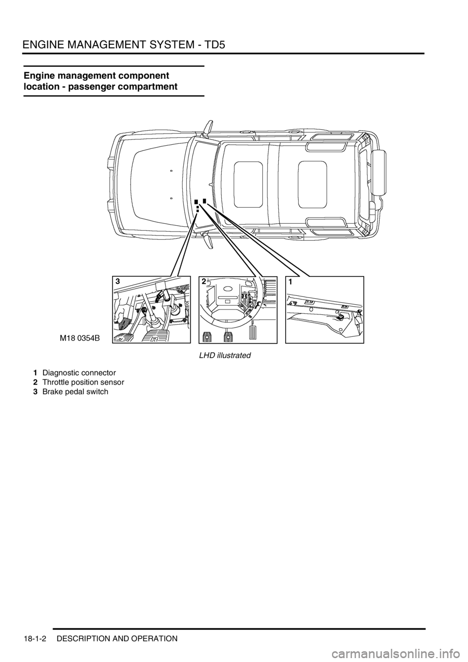
Engine management component
location - passenger compartment
LHD illustrated
1Diagnostic connector
2Throttle position sensor
3Brake pedal switch
Page 398 of 1672

ENGINE MANAGEMENT SYSTEM - TD5
DESCRIPTION AND OPERATION 18-1-5
1Mass air flow sensor
2Ambient air pressure sensor
3Manifold absolute pressure/ inlet air
temperature sensor
4Engine coolant temperature sensor
5Crankshaft speed and position sensor
6Throttle position sensor
7Fuel temperature sensor
8Brake pedal switch
9Clutch switch
10High/ Low ratio switch
11Main relay
12Malfunction indicator lamp
13Fuel pump relay
14Glow plug warning lamp
15Glow plugs16Electronic unit injectors
17Turbocharger wastegate modulator
18EGR modulator
19Diagnostic connector
20Engine control module
21Cruise control master switch
22Cruise control SET+ switch
23Cruise control RES switch
24Air conditioning clutch relay
25Air conditioning cooling fan relay
26Electronic automatic transmission ECU
27Self levelling and anti-lock brakes ECU
28Instrument cluster
29Body control unit