check engine light LAND ROVER DISCOVERY 2002 User Guide
[x] Cancel search | Manufacturer: LAND ROVER, Model Year: 2002, Model line: DISCOVERY, Model: LAND ROVER DISCOVERY 2002Pages: 1672, PDF Size: 46.1 MB
Page 258 of 1672

ENGINE - V8
REPAIRS 12-2-15
10.Remove cylinder head.
CAUTION: Support both ends of cylinder
head on blocks of wood.
11.Remove cylinder head gasket.
Refit
1.Clean mating faces of cylinder block and head
using suitable gasket removal spray and a
plastic scraper, ensure that bolt holes in block
are clean and dry. Clean mating faces of
cylinder head and exhaust manifold.
CAUTION: Do not use a metal scraper or
machined surfaces may be damaged.
2.Check head and block faces for warping and
pitting. If out of specification, renew head.
3.Fit cylinder head gasket with the word 'TOP'
uppermost.
CAUTION: Gaskets must be fitted dry.
4.Carefully fit cylinder head and locate on
dowels.
5.Lightly lubricate new cylinder head bolt threads
with clean engine oil. 6.Noting that bolts 1, 3 and 5 are longer than the
remainder, fit cylinder head bolts and tighten in
the sequence shown to 20 Nm (15 lbf.ft) then
90
° , and finally a further 90° .
CAUTION: Do not tighten bolts 180
° in one
operation.
7. Models with SAI: Fit new air injection adapters
and tighten to 33 Nm (24 lbf.ft).
8.Clean push rods.
9.Lubricate ends of push rods with clean engine
oil.
10.Fit push rods in their removed order.
11.Clean bases of rocker pillars and mating faces
on cylinder head.
12.Clean contact surfaces on rockers, valves and
push rods.
13.Lubricate contact surfaces and rocker shaft
with clean engine oil.
14.Fit rocker shaft assembly and engage push
rods.
15.Fit rocker shaft bolts and progressively tighten
to 40 Nm (30 lbf.ft).
16.Using new gaskets, position exhaust manifold
to cylinder head, fit bolts and using sequence
shown, tighten initially to 15 Nm (11 lbf.ft), then
finally to 36 Nm (28 lbf.ft).
Page 261 of 1672

ENGINE - V8
12-2-18 REPAIRS
Refit
1.Clean mating faces of cylinder block and head
using suitable gasket removal spray and a
plastic scraper, ensure that bolt holes in block
are clean and dry. Clean mating faces of
cylinder head and exhaust manifold.
CAUTION: Do not use a metal scraper or
machined surfaces may be damaged.
2.Check head and block faces for warping and
pitting. If out of specification, renew head.
3.Fit cylinder head gasket with the word 'TOP'
uppermost.
CAUTION: Gaskets must be fitted dry.
4.Carefully fit cylinder head and locate on
dowels.
5.Lightly lubricate new cylinder head bolt threads
with clean engine oil.
6.Noting that bolts 1, 3 and 5 are longer than the
remainder, fit bolts and tighten in the sequence
shown to 20 Nm (15 lbf.ft) then 90
°, and finally
a further 90
°.
CAUTION: Do not tighten bolts 180
° in one
operation.
7. Models with SAI: Fit new air injection adapters
and tighten to 33 Nm (24 lbf.ft).
8.Clean push rods.
9.Lubricate ends of push rods with clean engine
oil.
10.Fit push rods in their removed order.
11.Clean bases of rocker pillars and mating faces
on cylinder head.
12.Clean contact surfaces on rockers, valves and
push rods.
13.Lubricate contact surfaces and rocker shaft
with clean engine oil.
14.Fit rocker shaft assembly and engage push
rods.
15.Fit rocker shaft bolts and progressively tighten
to 40 Nm (30 lbf.ft). 16.Position alternator mounting bracket, fit bolts
and tighten to 40 Nm (30 lbf.ft).
17.Position auxiliary drive belt tensioner, fit bolt
and tighten to 45 Nm (33 lbf.ft).
18.Connect ht leads to spark plugs in their fitted
order.
19. Using new gaskets, fit exhaust manifold to
cylinder head. Fit bolts and using sequence
shown, tighten initially to 15 Nm (11 lbf.ft), then
finally tighten to 36 Nm (28 lbf.ft).
20. RH drive models: Fit brake servo heat shield.
+ MANIFOLDS AND EXHAUST
SYSTEMS - V8, REPAIRS, Heat shield -
brake servo - Without Secondary Air
Injection.
21.Position engine earth lead, fit bolt and tighten to
22 Nm (16 lbf.ft).
22.Fit inlet manifold gasket.
+ MANIFOLDS AND EXHAUST
SYSTEMS - V8, REPAIRS, Gasket - inlet
manifold - lower.
Page 304 of 1672
ENGINE - V8
OVERHAUL 12-2-61
9.Remove cylinder head gasket.
CAUTION: Support both ends of cylinder
head on blocks of wood.
Inspect
1.Clean mating faces of cylinder block and head
using suitable gasket removal spray and a
plastic scraper, ensure that bolt holes in block
are clean and dry.
CAUTION: Do not use a metal scraper or
machined surfaces may be damaged.
2.Check head and block faces for warping and
pitting.
lMaximum cylinder head warp = 0.05 mm
(0.002 in).
Note: Cylinder head can be refaced to 0.50
mm (0.02 in) maximum below head height –
See cylinder head overhaul.Reassembly
1.Fit cylinder head gasket with the word TOP
uppermost.
CAUTION: Gaskets must be fitted dry.
2.Carefully fit cylinder head and locate on
dowels.
3.Lightly lubricate new cylinder head bolt threads
with clean engine oil.
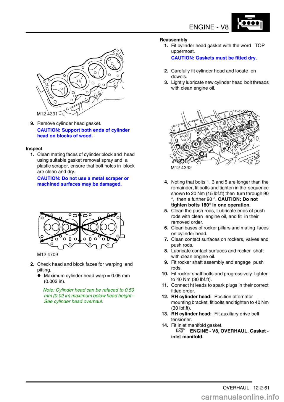
4.Noting that bolts 1, 3 and 5 are longer than the
remainder, fit bolts and tighten in the sequence
shown to 20 Nm (15 lbf.ft) then turn through 90
°, then a further 90 °. CAUTION: Do not
tighten bolts 180
° in one operation.
5.Clean the push rods, Lubricate ends of push
rods with clean engine oil, and fit in their
removed order.
6.Clean bases of rocker pillars and mating faces
on cylinder head.
7.Clean contact surfaces on rockers, valves and
push rods.
8.Lubricate contact surfaces and rocker shaft
with clean engine oil.
9.Fit rocker shaft assembly and engage push
rods.
10.Fit rocker shaft bolts and progressively tighten
to 40 Nm (30 lbf.ft).
11.Connect ht leads to spark plugs in their correct
fitted order.
12. RH cylinder head: Position alternator
mounting bracket, fit bolts and tighten to 40 Nm
(30 lbf.ft).
13. RH cylinder head: Fit auxiliary drive belt
tensioner.
14.Fit inlet manifold gasket.
+ ENGINE - V8, OVERHAUL, Gasket -
inlet manifold.
Page 309 of 1672
ENGINE - V8
12-2-66 OVERHAUL
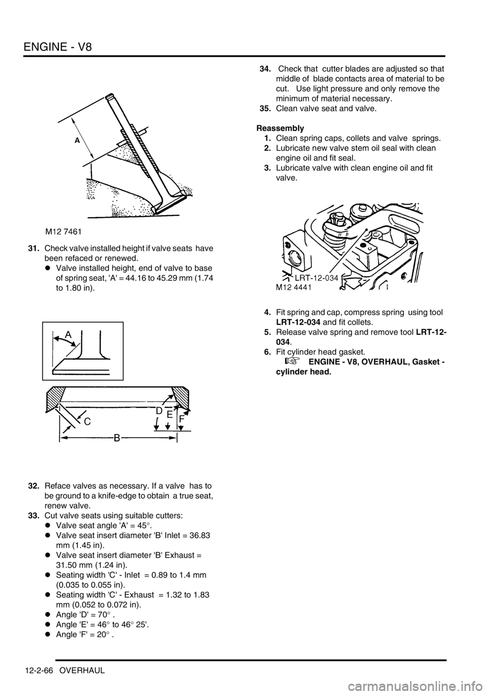
31.Check valve installed height if valve seats have
been refaced or renewed.
lValve installed height, end of valve to base
of spring seat, 'A' = 44.16 to 45.29 mm (1.74
to 1.80 in).
32.Reface valves as necessary. If a valve has to
be ground to a knife-edge to obtain a true seat,
renew valve.
33.Cut valve seats using suitable cutters:
lValve seat angle 'A' = 45
°.
lValve seat insert diameter 'B' Inlet = 36.83
mm (1.45 in).
lValve seat insert diameter 'B' Exhaust =
31.50 mm (1.24 in).
lSeating width 'C' - Inlet = 0.89 to 1.4 mm
(0.035 to 0.055 in).
lSeating width 'C' - Exhaust = 1.32 to 1.83
mm (0.052 to 0.072 in).
lAngle 'D' = 70
° .
lAngle 'E' = 46
° to 46° 25'.
lAngle 'F' = 20
° .34. Check that cutter blades are adjusted so that
middle of blade contacts area of material to be
cut. Use light pressure and only remove the
minimum of material necessary.
35.Clean valve seat and valve.
Reassembly
1.Clean spring caps, collets and valve springs.
2.Lubricate new valve stem oil seal with clean
engine oil and fit seal.
3.Lubricate valve with clean engine oil and fit
valve.
4.Fit spring and cap, compress spring using tool
LRT-12-034 and fit collets.
5.Release valve spring and remove tool LRT-12-
034.
6.Fit cylinder head gasket.
+ ENGINE - V8, OVERHAUL, Gasket -
cylinder head.
Page 314 of 1672
ENGINE - V8
OVERHAUL 12-2-71
Bearings - connecting rods
$% 12.17.16.01
Disassembly
1.Remove oil pick up strainer.
+ ENGINE - V8, OVERHAUL, Strainer
- oil pick-up.
2.Suitably mark cylinder reference number on
each connecting rod bearing cap.
3.Remove 2 bolts securing each connecting rod
bearing cap, remove caps and recover
connecting rod bearings.
CAUTION: Keep bearing caps, bearings and
bolts in their fitted order.
4.Push each connecting rod up cylinder bore
until connecting rods are clear of crankshaft
journals.
CAUTION: Ensure that connecting rods do
not contact cylinder bores.
5.Remove bearing shells from each connecting
rod.
Inspect
1.Clean crankshaft journals and bearing
locations in connecting rods.
2.Inspect connecting rod bearings for wear and
renew if necessary. Connecting rod bearings
are available in two oversizes.
lConnecting rod bearing 1st oversize = 0.254
mm (0.01 in).
lConnecting rod bearing 2nd oversize =
0.508 mm (0.02 in).3.Check crankshaft big-end journals for wear and
scoring. Measure for ovality; taking 3
measurements at 120
° intervals at each end
and at centre of journals.
lStandard journal = 55.500 to 55.513 mm
(2.20 to 2.22 in).
l1st undersize journal - 0.254 mm (0.01 in) =
55.246 to 55.259 mm (2.17 to 2.18 in).
l2nd undersize journal - 0.508 mm (0.02 in)
= 54.992 to 55.005 mm (2.16 to 2.165 in).
lJournal - max. ovality = 0.040 mm (0.002 in)
Reassembly
1.Clean connecting rod caps.
2.Lubricate connecting rod journals and bearing
shells with clean engine oil.
3.Fit bearing shells to connecting rods and caps.
4.Rotate crankshaft until connecting rod journals
are correctly positioned.
5.Taking care not to displace bearing shells, pull
connecting rods on to crankshaft journals.
6.Check that bearing shells are correctly located
in connecting rod bearing caps.
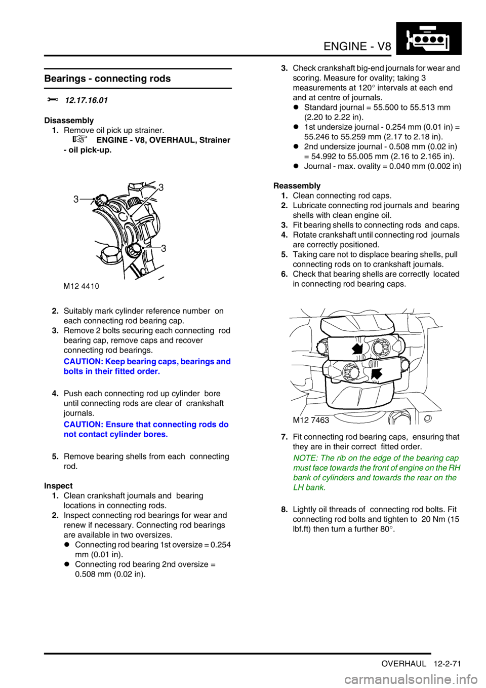
7.Fit connecting rod bearing caps, ensuring that
they are in their correct fitted order.
NOTE: The rib on the edge of the bearing cap
must face towards the front of engine on the RH
bank of cylinders and towards the rear on the
LH bank.
8.Lightly oil threads of connecting rod bolts. Fit
connecting rod bolts and tighten to 20 Nm (15
lbf.ft) then turn a further 80
°.
Page 317 of 1672
ENGINE - V8
12-2-74 OVERHAUL
Reassembly
1.Clean main bearing locations in cylinder block
and bearing caps.
2.Clean sealant from rear main bearing cap and
mating faces.
3.Fit key to keyway.
4.Check threads of main bearing cap bolts for
damage, renew bolts in pairs.
5.Lubricate grooved main bearing shells with
clean engine oil and fit to their locations in
cylinder block.
NOTE: Ensure that the flanged bearing is fitted
to the centre position.
6.Lubricate crankshaft journals with clean engine
oil.
7.Position crankshaft in cylinder block.
8.Attach a DTI to front of cylinder block, move
crankshaft rearwards, position stylus of gauge
on end of crankshaft and zero gauge.
9.Move crankshaft forwards, measure and
record end-float obtained.
l Crankshaft end-float = 0.08 to 0.26 mm
(0.003 to 0.01 in).
10.Lubricate plain bearing shells with clean
engine oil and fit to main bearing caps. 11.Fit main bearing caps 1 to 4 only at this stage,
ensuring that they are the correct way round
and in their fitted order.
12.Lightly lubricate threads of main bearing cap
bolts with clean engine oil.
13.Fit main bearing cap bolts but do not tighten at
this stage. Do not fit side bolts at this stage.
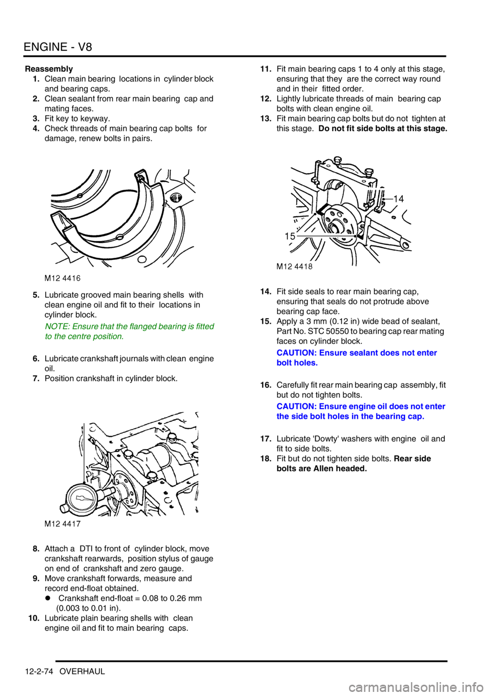
14.Fit side seals to rear main bearing cap,
ensuring that seals do not protrude above
bearing cap face.
15.Apply a 3 mm (0.12 in) wide bead of sealant,
Part No. STC 50550 to bearing cap rear mating
faces on cylinder block.
CAUTION: Ensure sealant does not enter
bolt holes.
16.Carefully fit rear main bearing cap assembly, fit
but do not tighten bolts.
CAUTION: Ensure engine oil does not enter
the side bolt holes in the bearing cap.
17.Lubricate 'Dowty' washers with engine oil and
fit to side bolts.
18.Fit but do not tighten side bolts. Rear side
bolts are Allen headed.
Page 346 of 1672
EMISSION CONTROL - V8
DESCRIPTION AND OPERATION 17-2-9
Emission Control Systems
Engine design has evolved in order to minimise the emission of harmful by-products. Emission control systems are
fitted to Land Rover vehicles which are designed to maintain the emission levels within the legal limits pertaining for
the specified market.
Despite the utilisation of specialised emission control equipment, it is still necessary to ensure that the engine is
correctly maintained and is in good mechanical order so that it operates at its optimal condition. In particular, ignition
timing has an effect on the production of HC and NO
x emissions, with the harmful emissions rising as the ignition
timing is advanced.
CAUTION: In many countries it is against the law for a vehicle owner or an unauthorised dealer to modify or
tamper with emission control equipment. In some cases, the vehicle owner and/or the dealer may even be
liable for prosecution.
The engine management ECM is fundamental for controlling the emission control systems. In addition to controlling
normal operation, the system complies with On Board Diagnostic (OBD) system strategies. The system monitors and
reports on faults detected with ignition, fuelling and exhaust systems which cause an excessive increase in tailpipe
emissions. This includes component failures, engine misfire, catalyst damage, catalyst efficiency, fuel evaporative
loss and exhaust leaks.
When an emission relevant fault is determined, the fault condition is stored in the ECM memory. For NAS vehicles,
the MIL warning light on the instrument pack will be illuminated when the fault is confirmed. Confirmation of a fault
condition occurs if the fault is still found to be present during the driving cycle subsequent to the one when the fault
was first detected.
+ ENGINE MANAGEMENT SYSTEM - V8, DESCRIPTION AND OPERATION, Description - engine
management.
The following types of supplementary control system are used to reduce harmful emissions released into the
atmosphere from the vehicle:
1Crankcase emission control – also known as blow-by gas emissions from the engine crankcase.
2Exhaust emission control – to limit the undesirable by-products of combustion.
3Fuel vapour evaporative loss control – to restrict the emission of fuel through evaporation from the fuel
system.
4Fuel leak detection system (NAS only) – there are two types of system which may be used to check the
evaporative emission system for the presence of leaks from the fuel tank to purge valve.
aVacuum leak detection test – checks for leaks down to 1 mm (0.04 in.) in diameter.
bPositive pressure leak detection test – utilises a leak detection pump to check for leaks down to 0.5 mm (0.02
in.) in diameter.
5Secondary air injection system (NAS only) – to reduce emissions experienced during cold starting.
Crankcase emission control system
The concentration of hydrocarbons in the crankcase of an engine is much greater than that in the vehicle's exhaust
system. In order to prevent the emission of these hydrocarbons into the atmosphere, crankcase emission control
systems are employed and are a standard legal requirement.
The crankcase ventilation system is an integral part of the air supply to the engine combustion chambers and it is
often overlooked when diagnosing problems associated with engine performance. A blocked ventilation pipe or filter
or excessive air leak into the inlet system through a damaged pipe or a leaking gasket can affect the air:fuel mixture,
performance and efficiency of the engine. Periodically check the ventilation hoses are not cracked and that they are
securely fitted to form airtight connections at their relevant ports.
The purpose of the crankcase ventilation system is to ensure that any noxious gas generated in the engine crankcase
is rendered harmless by complete burning of the fuel in the combustion chamber. Burning the crankcase vapours in
a controlled manner decreases the HC pollutants that could be emitted and helps to prevent the development of
sludge in the engine oil as well as increasing fuel economy.
Page 363 of 1672

EMISSION CONTROL - V8
17-2-26 DESCRIPTION AND OPERATION
Secondary air injection system
The secondary air injection (SAI) system comprises the following components:
lSecondary air injection pump
lSAI vacuum solenoid valve
lSAI control valves (2 off, 1 for each bank of cylinders)
lSAI pump relay
lVacuum reservoir
lVacuum harness and pipes
The secondary air injection system is used to limit the emission of carbon monoxide (CO) and hydrocarbons (HCs)
that are prevalent in the exhaust during cold starting of a spark ignition engine. The concentration of hydrocarbons
experienced during cold starting at low temperatures are particularly high until the engine and catalytic converter
reach normal operating temperature. The lower the cold start temperature, the greater the prevalence of
hydrocarbons emitted from the engine.
There are several reasons for the increase of HC emissions at low cold start temperatures, including the tendency for
fuel to be deposited on the cylinder walls, which is then displaced during the piston cycle and expunged during the
exhaust stroke. As the engine warms up through operation, the cylinder walls no longer retain a film of fuel and most
of the hydrocarbons will be burnt off during the combustion process.
The SAI pump is used to provide a supply of air into the exhaust ports in the cylinder head, onto the back of the
exhaust valves, during the cold start period. The hot unburnt fuel particles leaving the combustion chamber mix with
the air injected into the exhaust ports and immediately combust. This subsequent combustion of the unburnt and
partially burnt CO and HC particles help to reduce the emission of these pollutants from the exhaust system. The
additional heat generated in the exhaust manifold also provides rapid heating of the exhaust system catalytic
converters. The additional oxygen which is delivered to the catalytic converters also generate an exothermic reaction
which causes the catalytic converters to 'light off' quickly.
The catalytic converters only start to provide effective treatment of emission pollutants when they reach an operating
temperature of approximately 250
°C (482°F) and need to be between temperatures of 400°C (752°F) and 800°C
(1472
°F) for optimum efficiency. Consequently, the heat produced by the secondary air injection “afterburning”,
reduces the time delay before the catalysts reach an efficient operating temperature.
The engine control module (ECM) checks the engine coolant temperature when the engine is started, and if it is below
60º C (131
°F), the SAI pump is started. Secondary air injection will remain operational for a period controlled by the
ECM (76 seconds for NAS vehicles, 64 seconds for EU-3 vehicles). The SAI pump operation can be cut short due to
excessive engine speed or load.
Air from the SAI pump is supplied to the SAI control valves via pipework and an intermediate T-piece which splits the
air flow evenly to each bank.
At the same time the secondary air pump is started, the ECM operates a SAI vacuum solenoid valve, which opens to
allow vacuum from the reservoir to be applied to the vacuum operated SAI control valves on each side of the engine.
When the vacuum is applied to the SAI control valves, they open simultaneously to allow the air from the SAI pump
through to the exhaust ports. Secondary air is injected into the inner most exhaust ports on each bank.
When the ECM breaks the ground circuit to de-energise the SAI vacuum solenoid valve, the vacuum supply to the
SAI control valves is cut off and the valves close to prevent further air being injected into the exhaust manifold. At the
same time as the SAI vacuum solenoid valve is closed, the ECM opens the ground circuit to the SAI pump relay, to
stop the SAI pump.
A vacuum reservoir is included in the vacuum line between the intake manifold and the SAI vacuum solenoid valve.
This prevents changes in vacuum pressure from the intake manifold being passed on to cause fluctuations of the
secondary air injection solenoid valve. The vacuum reservoir contains a one way valve and ensures a constant
vacuum is available for the SAI vacuum solenoid valve operation. This is particularly important when the vehicle is at
high altitude.
Page 371 of 1672

EMISSION CONTROL - V8
17-2-34 DESCRIPTION AND OPERATION
Exhaust emission control operation
The oxygen content of the exhaust gas is monitored by heated oxygen sensors using either a four sensor (NAS only)
or two sensor setup, dependent on market destination and legislative requirements. Signals from the heated oxygen
sensors are input to the engine management ECM which correspond to the level of oxygen detected in the exhaust
gas. From ECM analysis of the data, necessary changes to the air:fuel mixture and ignition timing can be made to
bring the emission levels back within acceptable limits under all operating conditions.
Changes to the air:fuel ratio are needed when the engine is operating under particular conditions such as cold starting,
idle, cruise, full throttle or altitude. In order to maintain an optimum air:fuel ratio for differing conditions, the engine
management control system uses sensors to determine data which enable it to select the ideal ratio by increasing or
decreasing the air to fuel ratio. Improved fuel economy can be arranged by increasing the quantity of air to fuel to
create a lean mixture during part-throttle conditions, however lean running conditions are not employed on closed loop
systems where the maximum is
λ = 1. Improved performance can be established by supplying a higher proportion of
fuel to create a rich mixture during idle and full-throttle operation. Rich running at wide open throttle (WOT) for
performance and at high load conditions helps to keep the exhaust temperature down to protect the catalyst and
exhaust valves.
The voltage of the heated oxygen sensors at
λ = 1 is between 450 and 500 mV. The voltage decreases to 100 to 500
mV if there is an increase in oxygen content (
λ > 1) indicating a lean mixture. The voltage increases to 500 to 1000
mV if there is a decrease in oxygen content (
λ < 1), signifying a rich mixture.
The heated oxygen sensor needs to operate at high temperatures in order to function correctly (
≥ 350° C). To achieve
this the sensors are fitted with heater elements which are controlled by a pulse width modulated (PWM) signal from
the engine management ECM. The heater element warms the sensor's ceramic layer from the inside so that the
sensor is hot enough for operation. The heater elements are supplied with current immediately following engine start
and are ready for closed loop control within about 20 to 30 seconds (longer at cold ambient temperatures less than
0
°C (32°F)). Heating is also necessary during low load conditions when the temperature of the exhaust gases is
insufficient to maintain the required sensor temperatures. The maximum tip temperature is 930
° C.
A non-functioning heater element will delay the sensor's readiness for closed loop control and influences emissions.
A diagnostic routine is utilised to measure both sensor heater current and the heater supply voltage so its resistance
can be calculated. The function is active once per drive cycle, as long as the heater has been switched on for a pre-
defined period and the current has stabilised. The PWM duty cycle is carefully controlled to prevent thermal shock to
cold sensors.
The heated oxygen sensors age with mileage, causing an increase in the response time to switch from rich to lean
and lean to rich. This increase in response time influences the closed loop control and leads to progressively
increased emissions. The response time of the pre-catalytic converter sensors are monitored by measuring the period
of rich to lean and lean to rich switching. The ECM monitors the switching time, and if the threshold period is exceeded
(200 milliseconds), the fault will be detected and stored in the ECM as a fault code (the MIL light will be illuminated
on NAS vehicles). NAS vehicle engine calibration uses downstream sensors to compensate for aged upstream
sensors, thereby maintaining low emissions.
Diagnosis of electrical faults is continuously monitored for both the pre-catalytic converter sensors and the post-
catalytic converter sensors (NAS only). This is achieved by checking the signal against maximum and minimum
threshold for open and short circuit conditions. For NAS vehicles, should the pre- and post-catalytic converters be
inadvertently transposed, the lambda signals will go to maximum but opposite extremes and the system will
automatically revert to open loop fuelling. The additional sensors for NAS vehicles provide mandatory monitoring of
the catalyst conversion efficiency and long term fuelling adaptations.
Note that some markets do not legislate for closed loop fuelling control and in this instance no heated oxygen
sensors will be fitted to the exhaust system.
Page 373 of 1672

EMISSION CONTROL - V8
17-2-36 DESCRIPTION AND OPERATION
Exhaust Emission System Diagnostics
The engine management ECM contains an on-board diagnostics (OBD) system which performs a number of
diagnostic routines for detecting problems associated with the closed loop emission control system. The diagnostic
unit monitors ECM commands and system responses and also checks the individual sensor signals for plausibility,
these include:
lLambda ratio outside of operating band
lLambda heater diagnostic
lLambda period diagnostic
lPost-catalytic converter lambda adaptation diagnostic (NAS only)
lCatalyst monitoring diagnostic
Lambda ratio outside operating band
The system checks to ensure that the system is operating in a defined range around the stoichiometric point. If the
system determines that the upper or lower limits for the air:fuel ratio are being exceeded, the error is stored as a fault
code in the ECM diagnostic memory (the MIL light is illuminated on NAS vehicles).
Lambda heater diagnostic
The system determines the heater current and supply voltage so that the heater's resistance can be calculated. After
the engine has been started, the system waits for the heated oxygen sensors to warm up, then calculates the
resistance from the voltage and current measurements. If the value is found to be outside of the upper or lower
threshold values, then the fault is processed (the MIL light is illuminated on NAS vehicles).
Lambda period diagnostic
The pre-catalytic converter sensors are monitored. As the sensors age, the rich to lean and the lean to rich switching
delays increase, leading to increased emissions if the lambda control becomes inaccurate. If the switching period
exceeds a defined limit, the sensor fault is stored in the ECM diagnostic memory (the MIL light is illuminated on NAS
vehicles).
Post-catalytic converter lambda adaptation diagnostic (NAS only)
On NAS vehicles the ageing effects of the pre-catalytic converter sensors are compensated for by an adaptive value
derived from the post-catalytic converter sensors. This is a long term adaption which only changes slowly. For a rich
compensation the additive value is added to the rich delay time. For a lean compensation, the adaptive value is added
to the lean delay time. The adaptive time is monitored against a defined limit, and if the limit is exceeded, the fault is
stored in the ECM's diagnostic memory and the MIL light is illuminated on the instrument pack.
Catalyst monitoring diagnostic
On NAS specification vehicles the catalysts are monitored both individually and simultaneously for emission pollutant
conversion efficiency. The conversion efficiency of a catalyst is monitored by measuring the oxygen storage, since
there is a direct relationship between these two factors. The closed loop lambda control fuelling oscillations produce
pulses of oxygen upstream of the catalyst, as the catalyst efficiency deteriorates its ability to store oxygen is
decreased. The amplitudes of the signals from the pre-catalytic and post-catalytic converter heated oxygen sensors
are compared. As the oxygen storage decreases, the post-catalytic converter sensor begins to follow the oscillations
of the pre-catalytic converter heated oxygen sensors. Under steady state conditions the amplitude ratio is monitored
in different speed / load sites. There are three monitoring areas, and if the amplitude ratio exceeds a threshold in all
three areas the catalyst conversion limit is exceeded; the catalyst fault is stored in the diagnostic memory and the MIL
light is illuminated on the instrument pack. There is a reduced threshold value for both catalysts monitored as a pair.
In either case, a defective catalyst requires replacement of the downpipe assembly.