LAND ROVER DISCOVERY 2002 User Guide
DISCOVERY 2002
LAND ROVER
LAND ROVER
https://www.carmanualsonline.info/img/64/57246/w960_57246-0.png
LAND ROVER DISCOVERY 2002 User Guide
Page 28 of 1672

CONTENTS
CONTENTS 25
NAVIGATION SYSTEM ............................................................................ 87-1
DESCRIPTION AND OPERATION
Navigation System Component Location ........................................................................................ 87-1
Description ...................................................................................................................................... 87-2
REPAIRS
Interface electronic control unit (ECU) - remote control ................................................................. 87-11
Display unit .................................................................................................................................... 87-12
INSTRUMENTS......................................................................................... 88-1
DESCRIPTION AND OPERATION
Instrument pack .............................................................................................................................. 88-1
Instrument component location - Engine compartment / underneath vehicle ................................. 88-2
Instrument component location - Passenger compartment............................................................. 88-3
Instrument block diagram................................................................................................................ 88-4
Description ...................................................................................................................................... 88-5
Interior rear view mirror with compass (where fitted) ..................................................................... 88-42
REPAIRS
Clock ............................................................................................................................................... 88-45
Instrument pack ............................................................................................................................ 88-45
Page 342 of 1672
EMISSION CONTROL - V8
DESCRIPTION AND OPERATION 17-2-5
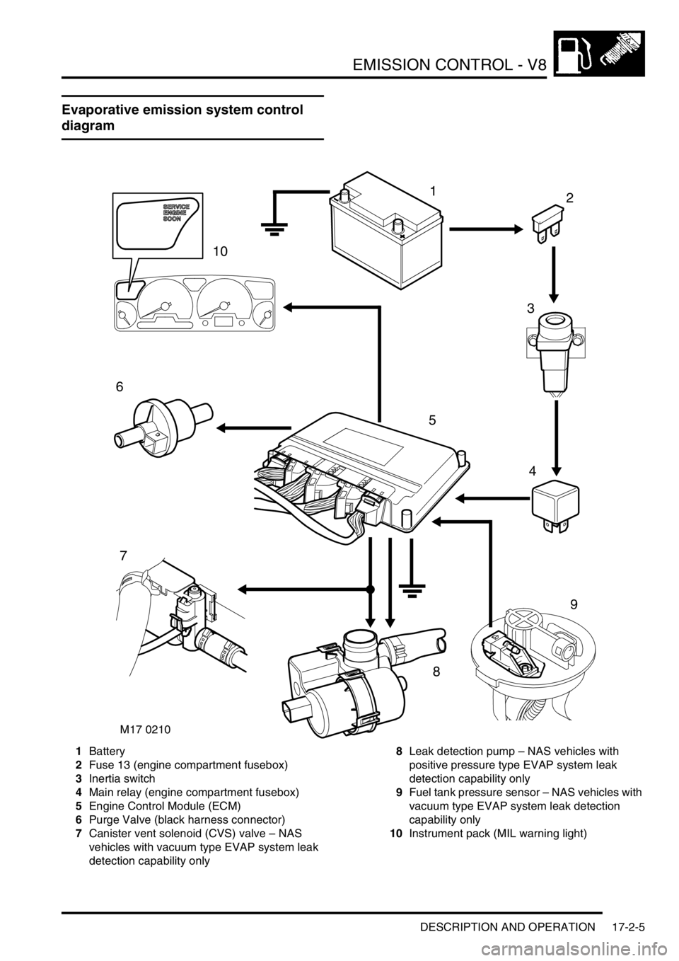
Evaporative emission system control
diagram
1Battery
2Fuse 13 (engine compartment fusebox)
3Inertia switch
4Main relay (engine compartment fusebox)
5Engine Control Module (ECM)
6Purge Valve (black harness connector)
7Canister vent solenoid (CVS) valve – NAS
vehicles with vacuum type EVAP system leak
detection capability only8Leak detection pump – NAS vehicles with
positive pressure type EVAP system leak
detection capability only
9Fuel tank pressure sensor – NAS vehicles with
vacuum type EVAP system leak detection
capability only
10Instrument pack (MIL warning light)
M17 0210
12
3
4
5
6
7
9
8
10
Page 345 of 1672
EMISSION CONTROL - V8
17-2-8 DESCRIPTION AND OPERATION
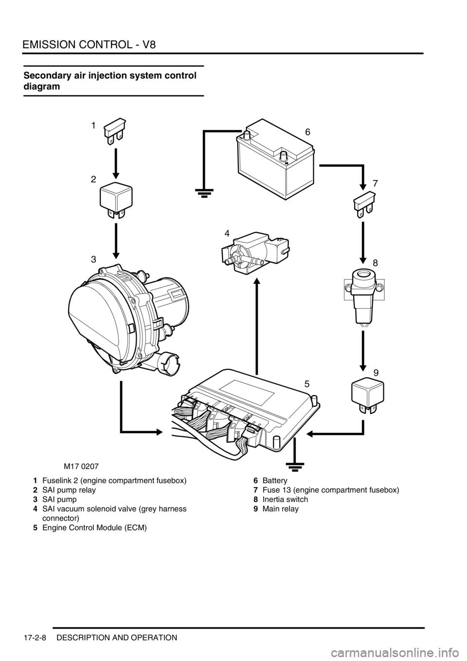
Secondary air injection system control
diagram
1Fuselink 2 (engine compartment fusebox)
2SAI pump relay
3SAI pump
4SAI vacuum solenoid valve (grey harness
connector)
5Engine Control Module (ECM)6Battery
7Fuse 13 (engine compartment fusebox)
8Inertia switch
9Main relay
9
M17 0207
1
2
3
4
5
7
6
8
Page 397 of 1672
ENGINE MANAGEMENT SYSTEM - TD5
18-1-4 DESCRIPTION AND OPERATION
Engine management block diagram
Page 461 of 1672
ENGINE MANAGEMENT SYSTEM - V8
18-2-4 DESCRIPTION AND OPERATION
Engine management block diagram
Page 513 of 1672
ENGINE MANAGEMENT SYSTEM - V8
18-2-56 DESCRIPTION AND OPERATION
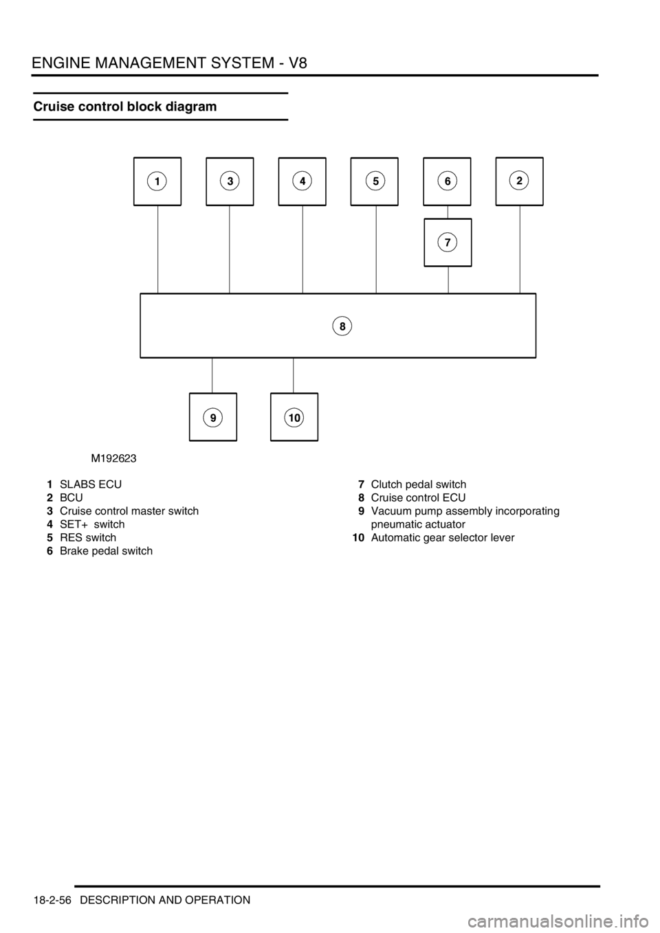
Cruise control block diagram
1SLABS ECU
2BCU
3Cruise control master switch
4SET+ switch
5RES switch
6Brake pedal switch7Clutch pedal switch
8Cruise control ECU
9Vacuum pump assembly incorporating
pneumatic actuator
10Automatic gear selector lever
Page 587 of 1672
COOLING SYSTEM - TD5
26-1-4 DESCRIPTION AND OPERATION
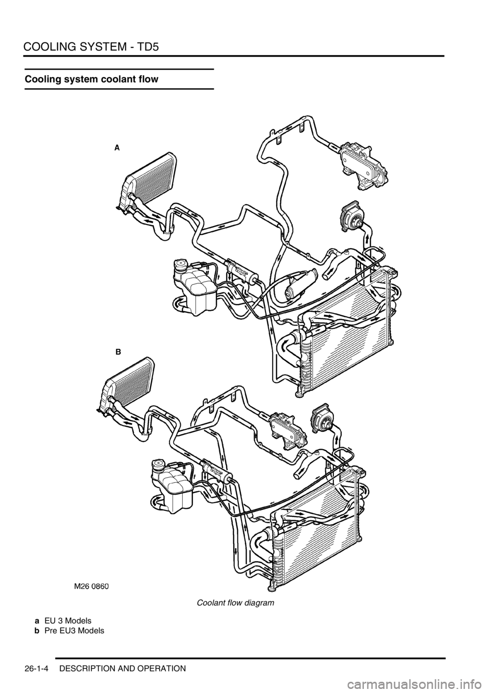
Cooling system coolant flow
Coolant flow diagram
aEU 3 Models
bPre EU3 Models
Page 949 of 1672
FRONT SUSPENSION
60-10 DESCRIPTION AND OPERATION
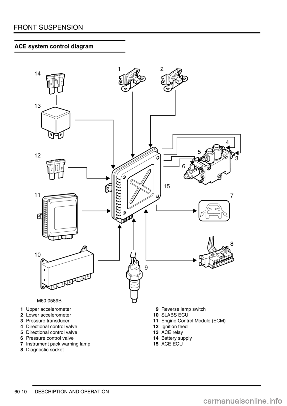
ACE system control diagram
1Upper accelerometer
2Lower accelerometer
3Pressure transducer
4Directional control valve
5Directional control valve
6Pressure control valve
7Instrument pack warning lamp
8Diagnostic socket9Reverse lamp switch
10SLABS ECU
11Engine Control Module (ECM)
12Ignition feed
13ACE relay
14Battery supply
15ACE ECU
M60 0589B
12
5
4
3
6
7
8
9
10
11
12
13
14
15
Page 964 of 1672
FRONT SUSPENSION
DESCRIPTION AND OPERATION 60-25
Operation
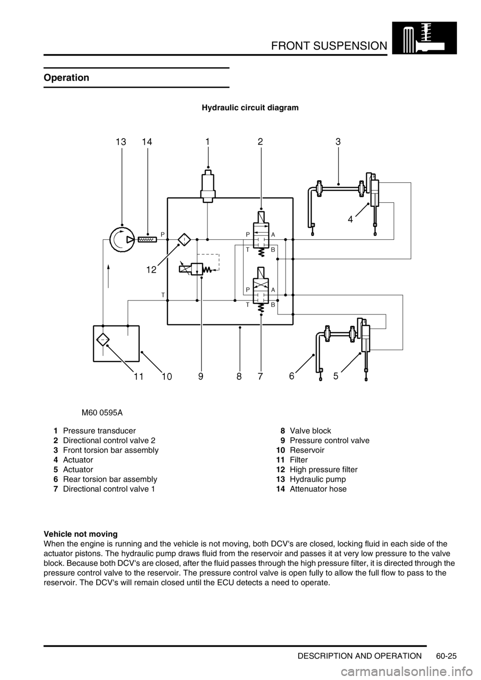
Hydraulic circuit diagram
1Pressure transducer
2Directional control valve 2
3Front torsion bar assembly
4Actuator
5Actuator
6Rear torsion bar assembly
7Directional control valve 18Valve block
9Pressure control valve
10Reservoir
11Filter
12High pressure filter
13Hydraulic pump
14Attenuator hose
Vehicle not moving
When the engine is running and the vehicle is not moving, both DCV's are closed, locking fluid in each side of the
actuator pistons. The hydraulic pump draws fluid from the reservoir and passes it at very low pressure to the valve
block. Because both DCV's are closed, after the fluid passes through the high pressure filter, it is directed through the
pressure control valve to the reservoir. The pressure control valve is open fully to allow the full flow to pass to the
reservoir. The DCV's will remain closed until the ECU detects a need to operate.
Page 1015 of 1672
REAR SUSPENSION
64-10 DESCRIPTION AND OPERATION
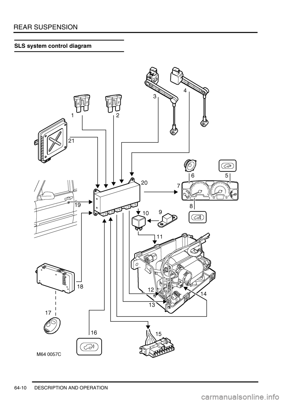
SLS system control diagram

