fuel filter LAND ROVER DISCOVERY 2002 User Guide
[x] Cancel search | Manufacturer: LAND ROVER, Model Year: 2002, Model line: DISCOVERY, Model: LAND ROVER DISCOVERY 2002Pages: 1672, PDF Size: 46.1 MB
Page 117 of 1672
MAINTENANCE
10-8 PROCEDURES
Brake fluid
Replace
1.Replace brake fluid.
+ BRAKES, ADJUSTMENTS, Brake
system bleeding.
Fuel filter - diesel engine
Replace
1.Replace filter element.
+ ENGINE MANAGEMENT SYSTEM -
Td5, REPAIRS, Element - fuel filter.
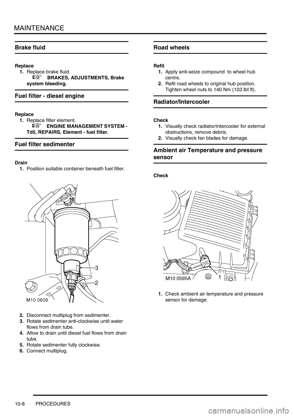
Fuel filter sedimenter
Drain
1.Position suitable container beneath fuel filter.
2.Disconnect multiplug from sedimenter.
3.Rotate sedimenter anti-clockwise until water
flows from drain tube.
4.Allow to drain until diesel fuel flows from drain
tube.
5.Rotate sedimenter fully clockwise.
6.Connect multiplug.
Road wheels
Refit
1.Apply anti-seize compound to wheel hub
centre.
2.Refit road wheels to original hub position.
Tighten wheel nuts to 140 Nm (103 lbf.ft).
Radiator/Intercooler
Check
1.Visually check radiator/intercooler for external
obstructions, remove debris.
2.Visually check fan blades for damage.
Ambient air Temperature and pressure
sensor
Check
1.Check ambient air temperature and pressure
sensor for damage.
Page 118 of 1672
MAINTENANCE
PROCEDURES 10-9
Doors, bonnet and fuel filler flap
Check
1.Check operation of each door, door lock,
bonnet catch and fuel filler flap. Ensure doors
close securely.
Lubricate
1.Lubricate door locks, hinges, check straps,
bonnet catch and fuel filler flap.
+ CAPACITIES, FLUIDS AND
LUBRICANTS, Lubrication.
Air suspension intake filter
Check
1.Check condition of filter and that filter is clean,
replace if necessary.
+ REAR SUSPENSION, REPAIRS,
Filter - intake - SLS.
Anti-freeze
Replace
1.Replace anti-freeze.
+ COOLING SYSTEM - Td5,
ADJUSTMENTS, Drain and refill.
+ COOLING SYSTEM - V8,
ADJUSTMENTS, Drain and refill.
Cooling system
Check
1.Check cooling, intercooler and heating systems
for leaks; hoses and oil pipes for security and
condition.
2.Check accessible hose clips for tightness.
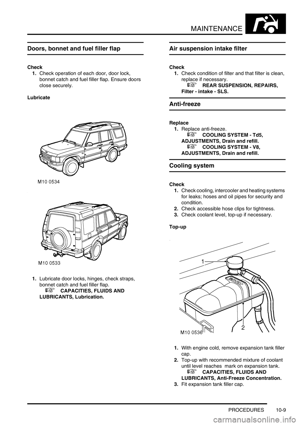
3.Check coolant level, top-up if necessary.
Top-up
1.With engine cold, remove expansion tank filler
cap.
2.Top-up with recommended mixture of coolant
until level reaches mark on expansion tank.
+ CAPACITIES, FLUIDS AND
LUBRICANTS, Anti-Freeze Concentration.
3.Fit expansion tank filler cap.
Page 151 of 1672
ENGINE - TD5
12-1-12 DESCRIPTION AND OPERATION
Description
General
The Td5 diesel engine is a 2.5 litre, 5 cylinder, in-line direct injection unit having 2 valves per cylinder, operated by a
single overhead camshaft. The engine emissions, on pre EU3 models, comply with ECD2 (European Commission
Directive) and on EU3 models, comply with ECD3 legislative requirements. Both models employ electronic engine
management control, positive crankcase ventilation and exhaust gas recirculation to limit the emission of pollutants.
The unit is water cooled and turbo-charged and is controlled by an electronic engine management system.
The engine is a monobloc cast iron construction with an aluminium stiffening plate fitted to the bottom of the cylinder
block to improve lower structure rigidity. The cylinder head and sump are cast aluminium. An acoustic cover is fitted
over the upper engine to reduce engine generated noise.
The engine utilises the following features:
lElectronic Unit Injectors (EUI's) controlled by an Engine Management System for precise fuel delivery under
all prevailing operating conditions.
lTurbocharging which delivers compressed air to the combustion chambers via an intercooler for improved
power output.
lFuel Cooler
lOil Cooler
lCentrifuge Oil Filter
lHydraulic Lash Adjusters with independent finger followers
Cylinder block components
The cylinder block components are described below:
Cylinder Block
The cylinders and crankcase are contained in a single cast iron construction. The cylinders are direct bored and
plateau honed with lubrication oil supplied via lubrication jets for piston and gudgeon pin lubrication and cooling. It is
not possible to rebore the cylinder block if the cylinders become worn or damaged. Three metal core plugs are fitted
to the three centre cylinders on the right hand side of the cylinder block.
Lubrication oil is distributed throughout the block via the main oil gallery to critical moving parts through channels
bored in the block which divert oil to the main and big-end bearings via oil holes machined into the crankshaft. Oil is
also supplied from the cylinder block main gallery to the five lubrication jets which cool and lubricate the piston and
gudgeon pins. Plugs are used to seal both ends of the main oil gallery at front and rear of the engine block. An oil
cooler is fitted to the LH side of the engine block; ports in the oil cooler assembly mate with ports in the cylinder block
to facilitate coolant flow. Oil is diverted through the oil cooler, centrifuge filter and full-flow filter before supplying the
main oil gallery. A tapping in the oil filter housing provides a lubrication source for the turbocharger bearings and an
oil pressure switch is included in a tapping in the oil cooler housing which determines whether sufficient oil pressure
is available to provide engine lubrication and cooling.
Cylinder cooling is achieved by water circulating through chambers in the engine block casting. A threaded coolant
jacket plug is located at the front RH side of the cylinder block.
Cast mounting brackets are bolted to both sides of the engine block for mounting the engine to the chassis on the LH
and RH hydramount studs.
The gearbox bolts directly to the engine block; a gearbox shim plate is located between the adjoining faces of the
gearbox and the flywheel side of the engine block and is fixed to the rear of the engine block by two bolts. Two hollow
metal dowels locate the rear of the cylinder block to the gearbox shim plate. The gearbox casing provides the
mounting for the starter motor.
A port is included at the rear left hand side of the cylinder block which connects to the turbocharger oil drain pipe to
return lubrication oil to the sump.
A plug sealing the lubrication cross-drilling gallery is located at the front right hand side of the cylinder block and plugs
for the main lubrication gallery is included at the front and rear of the cylinder block.
Page 216 of 1672
ENGINE - TD5
OVERHAUL 12-1-77
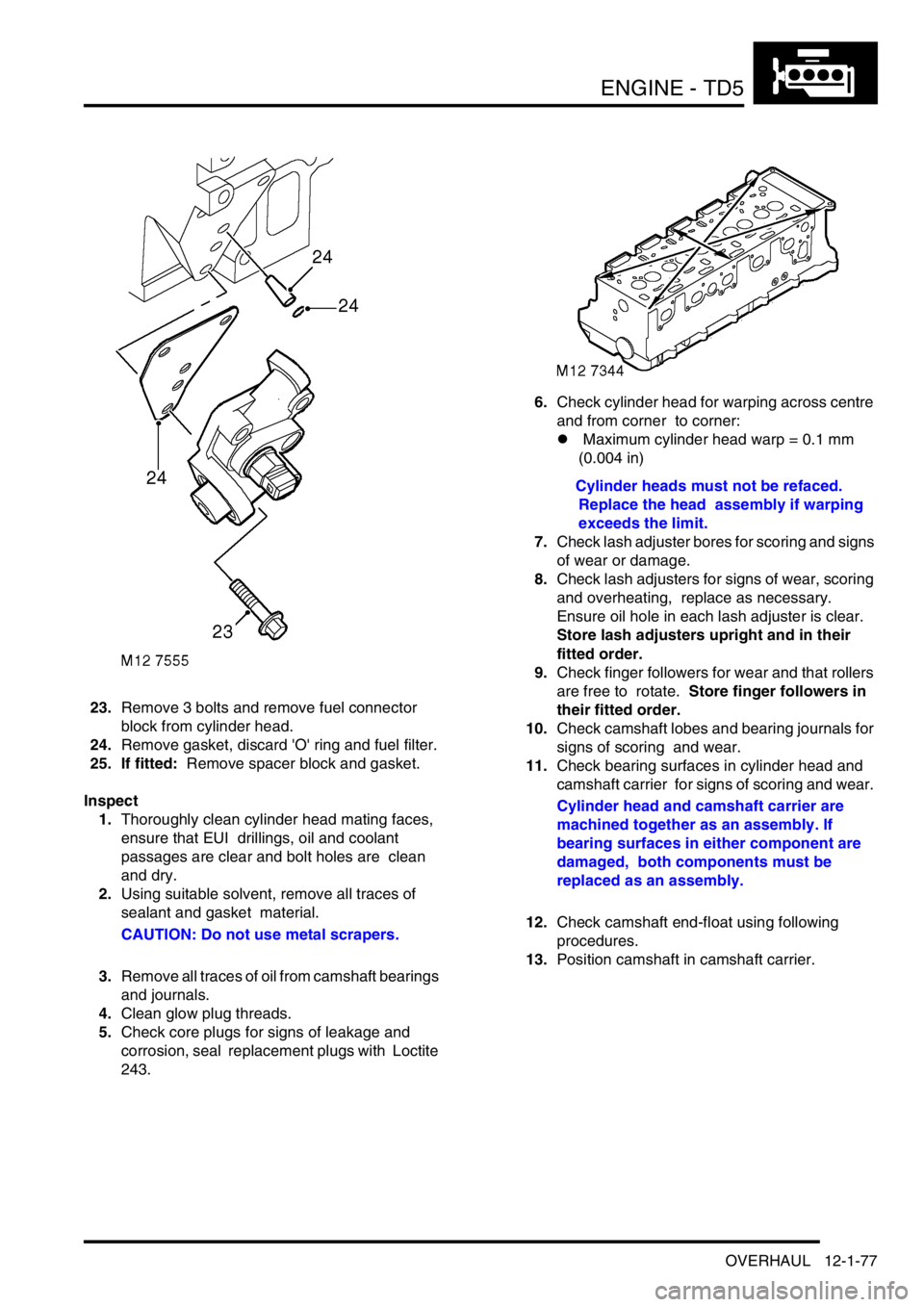
23.Remove 3 bolts and remove fuel connector
block from cylinder head.
24.Remove gasket, discard 'O' ring and fuel filter.
25. If fitted: Remove spacer block and gasket.
Inspect
1.Thoroughly clean cylinder head mating faces,
ensure that EUI drillings, oil and coolant
passages are clear and bolt holes are clean
and dry.
2.Using suitable solvent, remove all traces of
sealant and gasket material.
CAUTION: Do not use metal scrapers.
3.Remove all traces of oil from camshaft bearings
and journals.
4.Clean glow plug threads.
5.Check core plugs for signs of leakage and
corrosion, seal replacement plugs with Loctite
243.6.Check cylinder head for warping across centre
and from corner to corner:
l Maximum cylinder head warp = 0.1 mm
(0.004 in)
Cylinder heads must not be refaced.
Replace the head assembly if warping
exceeds the limit.
7.Check lash adjuster bores for scoring and signs
of wear or damage.
8.Check lash adjusters for signs of wear, scoring
and overheating, replace as necessary.
Ensure oil hole in each lash adjuster is clear.
Store lash adjusters upright and in their
fitted order.
9.Check finger followers for wear and that rollers
are free to rotate. Store finger followers in
their fitted order.
10.Check camshaft lobes and bearing journals for
signs of scoring and wear.
11.Check bearing surfaces in cylinder head and
camshaft carrier for signs of scoring and wear.
Cylinder head and camshaft carrier are
machined together as an assembly. If
bearing surfaces in either component are
damaged, both components must be
replaced as an assembly.
12.Check camshaft end-float using following
procedures.
13.Position camshaft in camshaft carrier.
Page 222 of 1672

ENGINE - TD5
OVERHAUL 12-1-83
9.Using tool LRT-12-154/3, fit new sealing
washer to each injector.
10.Support each end of cylinder head on blocks of
wood ensuring blocks are clear of valves.
11.Position reaction posts in their original fitted
order.
12.Carefully fit EUI's, ensuring they are in their
original fitted order and that each retainer is
located on its dowel.
CAUTION: If new EUI's are fitted, ensure
replacements are correct. Engine Serial No.
Prefixes 10P to 14P – Push rod bushes are
coloured BLACK or BLUE. Serial No.
Prefixes 15P to 19P – Push rod bushes are
coloured GREEN.
13.Fit new retainer bolts and tighten to 32 Nm (24
lbf.ft).
If new injectors are fitted they must be
programmed for use with the ECM using
TestBook.
14.Lubricate lash adjusters and bores with engine
oil.
15.Fit lash adjusters ensuring they are in their
original fitted order.
16.Lubricate finger followers with engine oil.
17.Fit finger followers ensuring they are in their
original fitted order.
18.Lubricate cams and bearing journals on
camshaft, cylinder head and camshaft carrier
with engine oil.
19.Position camshaft in cylinder head with the
timing pin hole in the vertical position.20.Apply an even film of sealant, Part No. STC
4600 to camshaft carrier face and spread to an
even film using a roller.
CAUTION: Ensure sealant does not block
oilways (arrowed) or contaminate camshaft
bearings. Assembly and bolt tightening
must be completed within 20 minutes of
applying sealant.
21.Fit camshaft carrier ensuring it is correctly
located on dowels.
22.Fit and lightly tighten new camshaft carrier
bolts.
23.Using sequence shown, progressively tighten
bolts to 25 Nm (18 lbf.ft).
24.Lubricate a new camshaft rear oil seal with
engine oil, fit seal using a suitable mandrel.
25.Position rocker shaft on camshaft carrier
ensuring rocker shaft is located on dowel.
26.Fit new rocker shaft retaining bolts and working
from the centre outwards, tighten rocker shaft
bolts to 32 Nm (24 lbf.ft).
27.Fit injector harness and connect multiplugs.
28.Clean fuel connector block and mating face.
29.Lubricate a new fuel filter 'O' ring with engine
oil.
Page 223 of 1672

ENGINE - TD5
12-1-84 OVERHAUL
30.Fit new fuel filter, 'O' ring, and gasket.
CAUTION: Gasket must be fitted dry.
31. If fitted: Fit fuel connector spacer block and
gasket.
32.Fit fuel connector block, fit bolts and tighten to
25 Nm (18 lbf.ft).
33.Clean glow plugs.
34.Fit glow plugs to cylinder head and tighten to
16 Nm (12 lbf.ft).
35.Fit new cylinder head gasket.
+ ENGINE - Td5, OVERHAUL, Gasket
- cylinder head.
36. Engine Serial No. Prefixes 15P to
19P:Lubricate new 'O' rings with engine oil and
fit to spill return pipe, fit pipe and tighten
connectors to 20 Nm (15 lbf.ft).
37.Before fitting the camshaft cover, the fuel
injector rockers must be adjusted following the
procedures given in Cylinder head gasket -
Refit.
+ ENGINE - Td5, OVERHAUL, Gasket
- cylinder head.
Gasket - engine sump
$% 12.60.38.01
Disassembly
1.Remove 2 bolts securing centrifuge oil drain
pipe to sump, remove and discard gasket.
2.Using sequence shown and noting their fitted
positions, remove 20 bolts securing sump to
cylinder block.
3.Release sump from locating dowels, remove
sump; remove and discard gasket.
Reassembly
1.Clean sump and mating faces, ensure bolt
holes in cylinder block are clean and dry.
2.Using suitable solvent, remove all traces of
sealant from joint faces of timing chain cover
and crankshaft rear oil seal housing.
3.Clean centrifuge oil drain pipe and mating
faces.
Page 269 of 1672

ENGINE - V8
12-2-26 REPAIRS
Engine assembly
$% 12.41.01.99
Remove
1.Drain engine oil and remove oil filter.
2.Remove radiator.
+ COOLING SYSTEM - V8, REPAIRS,
Radiator.
3.Remove upper inlet manifold.
+ MANIFOLDS AND EXHAUST
SYSTEMS - V8, REPAIRS, Gasket - inlet
manifold - upper - Without Secondary Air
Injection.
4.Remove ignition coil assemblies.
5.Position absorbent material to catch spillage
and disconnect fuel pipe from fuel rail.
CAUTION: Always fit plugs to open
connections to prevent contamination.
6.Release 2 hose clips and remove top hose.
7.Using a 15 mm spanner, release auxiliary drive
belt tension and remove drive belt. 8.Remove 3 bolts securing ACE pump, release
pump and tie aside.
9.Disconnect multiplug from A/C compressor.
10.Remove 4 bolts securing A/C compressor,
release compressor and tie aside.
Page 273 of 1672

ENGINE - V8
12-2-30 REPAIRS
Refit
1.Clean mating faces of engine and gearbox,
dowel and dowel holes.
2.Lubricate splines and bearing surface on first
motion shaft with grease.
3.With assistance position engine in engine bay,
align to gearbox and locate on dowels.
4.Position support brackets, fit bell housing bolts
and tighten to 50 Nm (37 lbf.ft).
5.Position engine mountings, fit nuts and tighten
to 85 Nm (63 lbf.ft).
6.Lower lifting equipment and remove from
engine.
7. Models with automatic gearbox: Align torque
converter to drive plate, fit bolts and tighten to
50 Nm (37 lbf.ft). Fit access plug.
8.Fit exhaust front pipe.
+ MANIFOLDS AND EXHAUST
SYSTEMS - V8, REPAIRS, Front pipe.
9.Position oil cooling pipe saddle clamps and
tighten bolts.
10.Position engine harness into foot well.
11.Connect 5 multiplugs to ECM.
12.Fit toe board and secure with trim fixings.
13.Connect engine harness earth to body and
secure with nut.
14.Connect engine harness to main harness
multiplug.
15.Connect multiplug to EVAP purge valve.
16.Connect engine harness multiplugs to fuse
box.
17.Connect starter lead to fuse box and secure
with nut.
18.Connect engine harness positive lead to
battery and tighten nut.
19.Fit fuse box cover.
20.Position engine earth lead and secure with
bolt.
21.Position coolant rail and secure with bolt.
22.Connect harness clips to coolant rail.
23.Connect hose to coolant rail and coolant pump
and secure with clips.
24.Connect PAS pump high and low pressure
pipes and secure with clips.
25.Position oil cooling pipe saddle clamp to PAS
pump housing and secure with bolt.
26.Clean A/C compressor and housing mating
faces, dowels and dowel holes. 27.Position A/C compressor, fit bolts and tighten
to 22 Nm (16 lbf.ft).
28.Connect multiplug to A/C compressor.
29.Clean ACE pump and housing mating faces,
dowels and dowel holes.
30.Position ACE pump, fit bolts and tighten to 22
Nm (16 lbf.ft).
31.Clean all pulley 'V's, fit auxiliary drive belt,
using a 15mm spanner, release belt tensioner
secure belt and re-tension drive belt .
32.Ensure auxiliary drive belt is correctly located
on all pulleys.
33.Fit radiator.
+ COOLING SYSTEM - V8, REPAIRS,
Radiator.
34.Fit top hose and secure with clips.
35.Connect fuel pipe to fuel rail.
36.Position ignition coils and connect ht leads.
37.Fit upper inlet manifold.
+ MANIFOLDS AND EXHAUST
SYSTEMS - V8, REPAIRS, Gasket - inlet
manifold - upper - Without Secondary Air
Injection.
38.Fit new oil filter and refill engine with oil.
+ ENGINE - V8, REPAIRS, Filter - oil.
+ MAINTENANCE, PROCEDURES,
Engine oil - V8 engine.
39.Top up gearbox oil.
+ MAINTENANCE, PROCEDURES,
Automatic gearbox.
Page 326 of 1672
EMISSION CONTROL - TD5
DESCRIPTION AND OPERATION 17-1-5
Exhaust gas recirculation
The exhaust gas recirculation (EGR) valve permits a controlled amount of exhaust gas to combine with the fresh air
entering the engine. The exhaust gas reduces the combustion temperature by delaying the fuel burning rate, which
assists in reducing the quantity of oxides of nitrogen.
On EU3 models, an EGR cooler is employed to further reduce the combustion temperature. By passing the exhaust
gas through a bundle of pipes flooded by coolant, the density of the exhaust gas going into the engine is increased.
This process further reduces the amount of oxygen, which in turn, further reduces the amount of NO
2 in the exhaust.
Recirculating too much exhaust gas can result in higher emissions of soot, HC and CO due to insufficient air. The
recirculated exhaust gas must be limited so that there is sufficient oxygen available for combustion of the injected fuel
in the combustion chamber, to do this the Engine Control Module (ECM) is used to control the precise quantity of
exhaust gas to be recirculated in accordance with the prevailing operating conditions. Influencing factors include:
lthe mass of air flow detected by the mass air flow sensor.
+ ENGINE MANAGEMENT SYSTEM - Td5, DESCRIPTION AND OPERATION, Description.
lthe ambient air pressure, determined by the ambient air pressure sensor which is used to initiate adjustments
to reduce the amount of smoke produced at high altitudes.
+ ENGINE MANAGEMENT SYSTEM - Td5, DESCRIPTION AND OPERATION, Description.
Other factors which are taken into consideration by the engine management system for determining the optimum
operating condition include:
lManifold inlet air temperature
lCoolant temperature
lEngine speed
lFuel delivered
The main components of the EGR system are as follows.
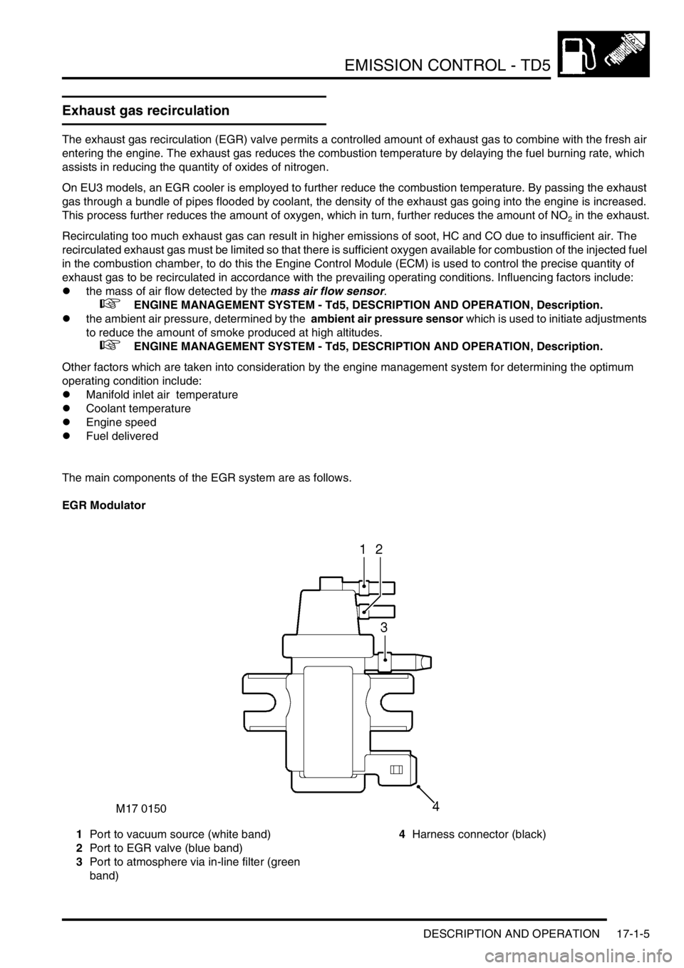
EGR Modulator
1Port to vacuum source (white band)
2Port to EGR valve (blue band)
3Port to atmosphere via in-line filter (green
band)4Harness connector (black)
Page 341 of 1672

EMISSION CONTROL - V8
17-2-4 DESCRIPTION AND OPERATION
Evaporative emission system (with
positive pressure leak detection)
component layout (NAS only)
1Purge valve
2Service port
3Air filter canister
4EVAP canister breather tube
5Leak detection pump
6EVAP canister
7Vent pipe – fuel tank to EVAP canister
8Liquid vapour separator (metal)9Fuel filler cap
10Fuel filler
11Fuel tank breather assembly
12Vent hose
13Roll over valves (inside fuel tank)
14Fuel tank
15Purge line connection to engine manifold
M17 0208
3
1
7
4
14
11
6
8
10
13
12
15
2
5
9