remove seats LAND ROVER DISCOVERY 2002 User Guide
[x] Cancel search | Manufacturer: LAND ROVER, Model Year: 2002, Model line: DISCOVERY, Model: LAND ROVER DISCOVERY 2002Pages: 1672, PDF Size: 46.1 MB
Page 574 of 1672
FUEL DELIVERY SYSTEM - V8
DESCRIPTION AND OPERATION 19-2-9
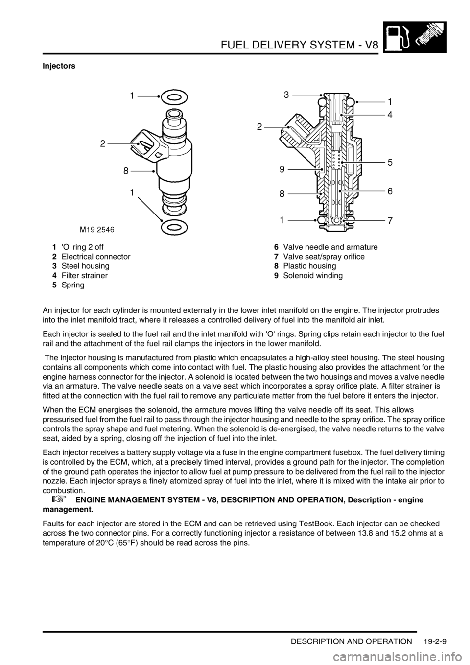
Injectors
1'O' ring 2 off
2Electrical connector
3Steel housing
4Filter strainer
5Spring6Valve needle and armature
7Valve seat/spray orifice
8Plastic housing
9Solenoid winding
An injector for each cylinder is mounted externally in the lower inlet manifold on the engine. The injector protrudes
into the inlet manifold tract, where it releases a controlled delivery of fuel into the manifold air inlet.
Each injector is sealed to the fuel rail and the inlet manifold with 'O' rings. Spring clips retain each injector to the fuel
rail and the attachment of the fuel rail clamps the injectors in the lower manifold.
The injector housing is manufactured from plastic which encapsulates a high-alloy steel housing. The steel housing
contains all components which come into contact with fuel. The plastic housing also provides the attachment for the
engine harness connector for the injector. A solenoid is located between the two housings and moves a valve needle
via an armature. The valve needle seats on a valve seat which incorporates a spray orifice plate. A filter strainer is
fitted at the connection with the fuel rail to remove any particulate matter from the fuel before it enters the injector.
When the ECM energises the solenoid, the armature moves lifting the valve needle off its seat. This allows
pressurised fuel from the fuel rail to pass through the injector housing and needle to the spray orifice. The spray orifice
controls the spray shape and fuel metering. When the solenoid is de-energised, the valve needle returns to the valve
seat, aided by a spring, closing off the injection of fuel into the inlet.
Each injector receives a battery supply voltage via a fuse in the engine compartment fusebox. The fuel delivery timing
is controlled by the ECM, which, at a precisely timed interval, provides a ground path for the injector. The completion
of the ground path operates the injector to allow fuel at pump pressure to be delivered from the fuel rail to the injector
nozzle. Each injector sprays a finely atomized spray of fuel into the inlet, where it is mixed with the intake air prior to
combustion.
+ ENGINE MANAGEMENT SYSTEM - V8, DESCRIPTION AND OPERATION, Description - engine
management.
Faults for each injector are stored in the ECM and can be retrieved using TestBook. Each injector can be checked
across the two connector pins. For a correctly functioning injector a resistance of between 13.8 and 15.2 ohms at a
temperature of 20
°C (65°F) should be read across the pins.
Page 578 of 1672
FUEL DELIVERY SYSTEM - V8
REPAIRS 19-2-13
REPAIRS
Switch - inertia - fuel cut-off
$% 19.22.09
Remove
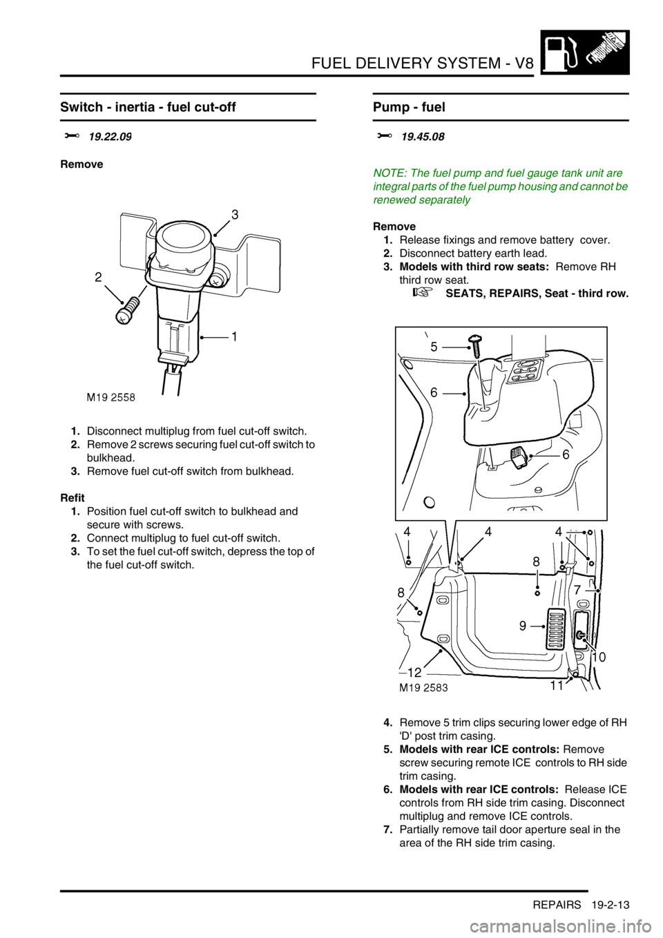
1.Disconnect multiplug from fuel cut-off switch.
2.Remove 2 screws securing fuel cut-off switch to
bulkhead.
3.Remove fuel cut-off switch from bulkhead.
Refit
1.Position fuel cut-off switch to bulkhead and
secure with screws.
2.Connect multiplug to fuel cut-off switch.
3.To set the fuel cut-off switch, depress the top of
the fuel cut-off switch.
Pump - fuel
$% 19.45.08
NOTE: The fuel pump and fuel gauge tank unit are
integral parts of the fuel pump housing and cannot be
renewed separately
Remove
1.Release fixings and remove battery cover.
2.Disconnect battery earth lead.
3. Models with third row seats: Remove RH
third row seat.
+ SEATS, REPAIRS, Seat - third row.
4.Remove 5 trim clips securing lower edge of RH
'D' post trim casing.
5. Models with rear ICE controls: Remove
screw securing remote ICE controls to RH side
trim casing.
6. Models with rear ICE controls: Release ICE
controls from RH side trim casing. Disconnect
multiplug and remove ICE controls.
7.Partially remove tail door aperture seal in the
area of the RH side trim casing.
Page 579 of 1672
FUEL DELIVERY SYSTEM - V8
19-2-14 REPAIRS
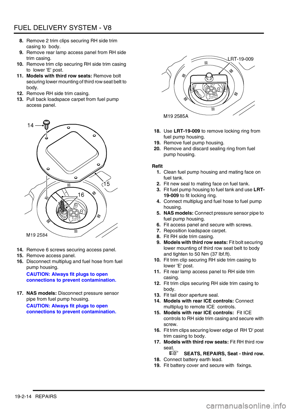
8.Remove 2 trim clips securing RH side trim
casing to body.
9.Remove rear lamp access panel from RH side
trim casing.
10.Remove trim clip securing RH side trim casing
to lower 'E' post.
11. Models with third row seats: Remove bolt
securing lower mounting of third row seat belt to
body.
12.Remove RH side trim casing.
13.Pull back loadspace carpet from fuel pump
access panel.
14.Remove 6 screws securing access panel.
15.Remove access panel.
16.Disconnect multiplug and fuel hose from fuel
pump housing.
CAUTION: Always fit plugs to open
connections to prevent contamination.
17. NAS models: Disconnect pressure sensor
pipe from fuel pump housing.
CAUTION: Always fit plugs to open
connections to prevent contamination.18.Use LRT-19-009 to remove locking ring from
fuel pump housing.
19.Remove fuel pump housing.
20.Remove and discard sealing ring from fuel
pump housing.
Refit
1.Clean fuel pump housing and mating face on
fuel tank.
2.Fit new seal to mating face on fuel tank.
3.Fit fuel pump housing to fuel tank and use LRT-
19-009 to fit locking ring.
4.Connect multiplug and fuel hose to fuel pump
housing.
5. NAS models: Connect pressure sensor pipe to
fuel pump housing.
6.Fit access panel and secure with screws.
7.Reposition loadspace carpet.
8.Fit RH side trim casing.
9. Models with third row seats: Fit bolt securing
lower mounting of third row seat belt to body
and tighten to 50 Nm (37 lbf.ft).
10.Fit trim clip securing RH side trim casing to
lower 'E' post.
11.Fit rear lamp access panel to RH side trim
casing.
12.Fit trim clips securing RH side trim casing to
body.
13.Fit tail door aperture seal.
14. Models with rear ICE controls: Connect
multiplug to remote ICE controls.
15. Models with rear ICE controls: Fit ICE
controls to RH side trim casing and secure with
screw.
16.Fit trim clips securing lower edge of RH 'D' post
trim casing to body.
17. Models with third row seats: Fit RH third row
seat.
+ SEATS, REPAIRS, Seat - third row.
18.Connect battery earth lead.
19.Fit battery cover and secure with fixings.
Page 937 of 1672
STEERING
57-50 REPAIRS
Drag link
$% 57.55.17
Remove
1.Raise front of vehicle.
WARNING: Do not work on or under a
vehicle supported only by a jack. Always
support the vehicle on safety stands.
2. RHD vehicles: Remove the LH front road
wheel.
3. LHD vehicles: Remove the RH front road
wheel.
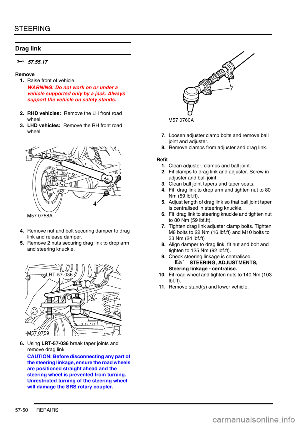
4.Remove nut and bolt securing damper to drag
link and release damper.
5.Remove 2 nuts securing drag link to drop arm
and steering knuckle.
6.Using LRT-57-036 break taper joints and
remove drag link.
CAUTION: Before disconnecting any part of
the steering linkage, ensure the road wheels
are positioned straight ahead and the
steering wheel is prevented from turning.
Unrestricted turning of the steering wheel
will damage the SRS rotary coupler.7.Loosen adjuster clamp bolts and remove ball
joint and adjuster.
8.Remove clamps from adjuster and drag link.
Refit
1.Clean adjuster, clamps and ball joint.
2.Fit clamps to drag link and adjuster. Screw in
adjuster and ball joint.
3.Clean ball joint tapers and taper seats.
4.Fit drag link to drop arm and tighten nut to 80
Nm (59 lbf.ft).
5.Adjust length of drag link so that ball joint taper
is centralised in steering knuckle.
6.Fit drag link to steering knuckle and tighten nut
to 80 Nm (59 lbf.ft).
7.Tighten drag link adjuster clamp bolts. Tighten
M8 bolts to 22 Nm (16 lbf.ft) and M10 bolts to
33 Nm (24 lbf.ft)
8.Align damper to drag link, fit nut and bolt and
tighten to 125 Nm (92 lbf.ft).
9.Check steering linkage is centralised.
+ STEERING, ADJUSTMENTS,
Steering linkage - centralise.
10.Fit road wheel and tighten nuts to 140 Nm (103
lbf.ft).
11.Remove stand(s) and lower vehicle.
Page 943 of 1672

FRONT SUSPENSION
60-4 DESCRIPTION AND OPERATION
Description
General
The front suspension comprises two dampers and coil springs, two radius arms, a Panhard rod and an anti-roll bar.
The front axle provides the location points for the dampers, springs, radius arms and the Panhard rod.
The anti-roll bar assembly is an essential part of the front suspension. On vehicles without Active Cornering
Enhancement (ACE) a conventional 'passive' anti-roll bar is fitted. On vehicles fitted with the ACE system, a thicker
diameter anti-roll bar, known as a torsion bar, is used with an actuator at one end.
+ FRONT SUSPENSION, DESCRIPTION AND OPERATION, Description - ACE.
The hydraulic dampers and coil springs provide springing for each front wheel. The long travel dampers, springs and
radius arms provide maximum axle articulation and wheel travel for off-road driving. The front axle is controlled
longitudinally by two forged steel radius arms and transversely by a Panhard rod.
Radius arms
Each radius arm is manufactured from forged steel. Two bushes are pressed into the forward end of the radius arm.
The forward end of the radius arm is located in a fabricated bracket on the axle and secured through the bushes with
two bolts and nuts. A bush is pressed into the rear of the radius arm which is also located in a fabricated bracket on
each chassis longitudinal and secured through the bush with a bolt and nut.
The radius arms prevent longitudinal movement of the front axle and because of their length allow maximum axle
articulation. The stiffness of the bushes in each radius arm also contributes to the vehicle roll stiffness.
Each radius arm has a notch on its lower edge which provides location for the vehicle jack.
Dampers
Two conventional telescopic dampers are used to control body/axle movement. A turret is located on a bracket welded
to the chassis. The upper spring seat has four studs which pass through holes in the bracket and align with
corresponding holes in the turret. Four nuts are screwed onto the studs and secure the turret and upper spring seat
to the chassis.
A fabricated platform is welded to the axle. The platform has two captive nuts which provide for the attachment of the
damper. A lower spring seat is located on the platform. Each spring seat is handed and has a bracket which secures
the ABS sensor harness and the front brake hose.
Each damper is fitted with a bush at its upper end. The bush locates in the top of the turret and is secured with a cross
bolt. The lower attachment point for the damper is also fitted with a bush. This bush has a spindle through its centre
with a hole at each end. The spindle is seated on the lower spring seat and the axle platform and secured with two
bolts. The coil spring is fitted in a compressed state between the upper and lower spring seats and assists the damper
in controlling the body/axle movement. The upper and lower bushes are replaceable items.
Rubber bump stops are fitted to the chassis above each end of the axle. The bump stops are progressive in their
compression and prevent the axle from contacting the chassis in the event of maximum suspension travel being
reached. The bump stops revert to their original shape once the compression load has been removed from them.
The damper functions by restricting the flow of a hydraulic fluid through internal galleries within the damper body. A
chromium plated rod moves axially within the damper. As the rod moves, its movement is limited by the flow of fluid
through the galleries thus providing damping of undulations in the terrain. The damper rod is sealed at its exit point
from the body to maintain fluid within the unit and prevent the ingress of dirt and moisture. The seal also acts as a
wiper to keep the rod outer diameter clean. A plastic shroud protects the rod and slides over the body as the damper
moves. The coil spring aids the damper to extend after being compressed and also aids the damping process.
Page 958 of 1672

FRONT SUSPENSION
DESCRIPTION AND OPERATION 60-19
The right hand end of the torsion bar has a machined spigot which provides for the attachment of the forged steel
short and long arms. The spigot for the short arm is splined and mates with splines in the short arm. The short arm is
located in a specific position on the splines and clamped to the spigot with a Torx bolt and locknut. The short arm is
not a serviceable item other than the actuator attachment bush. The smaller spigot diameter locates the long arm.
The long arm is fitted with a slipper bush which is located on the spigot and secured with a large washer and a special
bolt. The slipper bush comprises two inner and two outer bushes which are installed from each side of the long arm.
The outer bushes have three lugs which locate in the long arm to prevent the bush from rotating. The long arm also
provides the attachment point for the actuator piston rod and the anti-roll bar link.
The actuator has a forked end which locates on the bush in the short arm and is secured with a bolt and nut. The
piston rod of the actuator locates through a hole in a cast boss on the long arm which is fitted with a special bush. A
shoulder on the piston rod seats in a hole in the bush and a locknut on the end of the piston rod secures the rod to
the long arm and bush.
The front torsion bar is attached to the front chassis cross member. Two rubber bushes are fitted to the torsion bar
and are located in clamp plates. The clamp plates are located in slots in the cross member and secured with bolts.
The rear torsion bar is attached to the tubular cross member at the rear section of the chassis. Two rubber bushes
are fitted to the torsion bar and are located in clamp plates. The clamp plates are located in fabricated brackets
attached to the tubular cross-member and secured with bolts.
Two anti-roll bar links are mounted on brackets on the front and rear axles. Each anti-roll bar link is fitted with a
spherical bearing at each end. One bearing is attached to the link at a 90
° angle. The threaded shank of the bearing
is located through a hole in a bracket on the axle and secured with a locknut; a washer is installed on the threaded
shank between the bearing and the bracket. The second spherical bearing is attached in-line with the link and locates
in the torsion bar on the left hand side and the long arm on the right hand side. The front anti-roll bar links are longer
than the rear links and are not interchangeable.
Accelerometers
Two accelerometers are used for the ACE system. The upper accelerometer is mounted on a bracket, behind the
headlining adjacent to the rear view mirror and the sunroof ECU. The lower accelerometer is located on a bracket on
the inner sill panel under the RH front floor.
The lower accelerometer is the primary sensor used to measure lateral acceleration of the vehicle for roll control. The
upper accelerometer is used by the ECU for roll correction and fault detection in conjunction with the lower
accelerometer.
Each accelerometer is a solid state capacitive acceleration sensor and operates on a 5 V supply from the ECU. The
upper and lower sensors can measure acceleration in the range of
± 1.10 g and return an output to the ECU of
between 0.5 and 4.5 V.
Failures of an accelerometer are recorded by the ECU and can be retrieved using TestBook. A special tool is required
to remove and replace a sensor in the bracket.
Page 970 of 1672
FRONT SUSPENSION
REPAIRS 60-31
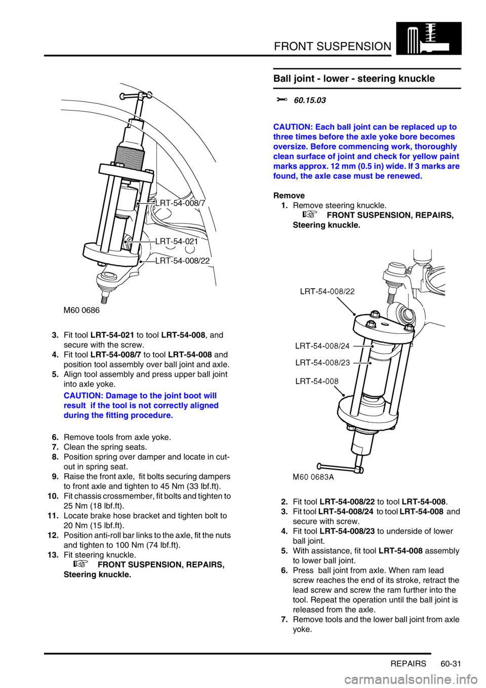
3.Fit tool LRT-54-021 to tool LRT-54-008, and
secure with the screw.
4.Fit tool LRT-54-008/7 to tool LRT-54-008 and
position tool assembly over ball joint and axle.
5.Align tool assembly and press upper ball joint
into axle yoke.
CAUTION: Damage to the joint boot will
result if the tool is not correctly aligned
during the fitting procedure.
6.Remove tools from axle yoke.
7.Clean the spring seats.
8.Position spring over damper and locate in cut-
out in spring seat.
9.Raise the front axle, fit bolts securing dampers
to front axle and tighten to 45 Nm (33 lbf.ft).
10.Fit chassis crossmember, fit bolts and tighten to
25 Nm (18 lbf.ft).
11.Locate brake hose bracket and tighten bolt to
20 Nm (15 lbf.ft).
12.Position anti-roll bar links to the axle, fit the nuts
and tighten to 100 Nm (74 lbf.ft).
13.Fit steering knuckle.
+ FRONT SUSPENSION, REPAIRS,
Steering knuckle.
Ball joint - lower - steering knuckle
$% 60.15.03
CAUTION: Each ball joint can be replaced up to
three times before the axle yoke bore becomes
oversize. Before commencing work, thoroughly
clean surface of joint and check for yellow paint
marks approx. 12 mm (0.5 in) wide. If 3 marks are
found, the axle case must be renewed.
Remove
1.Remove steering knuckle.
+ FRONT SUSPENSION, REPAIRS,
Steering knuckle.
2.Fit tool LRT-54-008/22 to tool LRT-54-008.
3.Fit tool LRT-54-008/24 to tool LRT-54-008 and
secure with screw.
4.Fit tool LRT-54-008/23 to underside of lower
ball joint.
5.With assistance, fit tool LRT-54-008 assembly
to lower ball joint.
6.Press ball joint from axle. When ram lead
screw reaches the end of its stroke, retract the
lead screw and screw the ram further into the
tool. Repeat the operation until the ball joint is
released from the axle.
7.Remove tools and the lower ball joint from axle
yoke.
Page 972 of 1672
FRONT SUSPENSION
REPAIRS 60-33
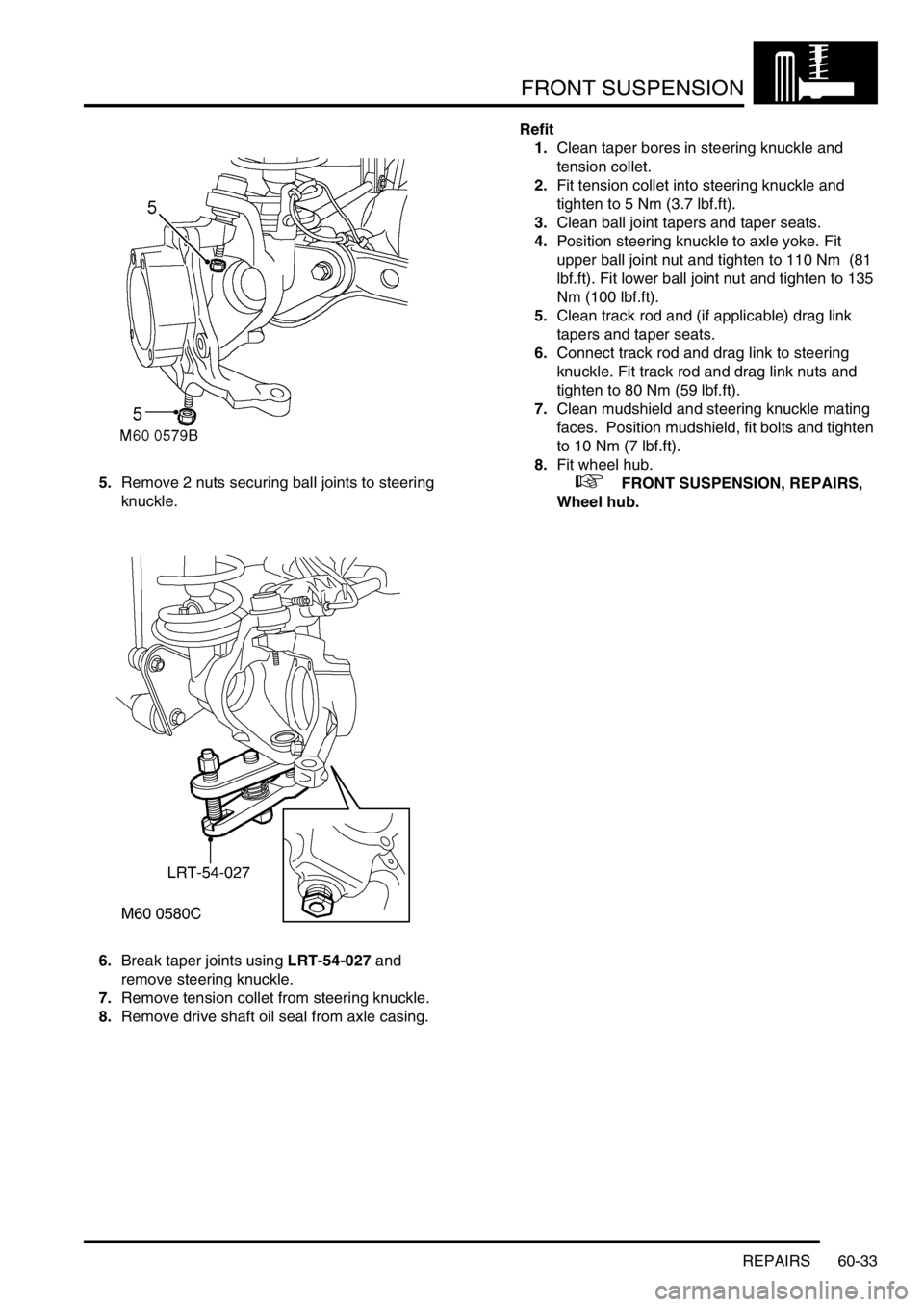
5.Remove 2 nuts securing ball joints to steering
knuckle.
6.Break taper joints using LRT-54-027 and
remove steering knuckle.
7.Remove tension collet from steering knuckle.
8.Remove drive shaft oil seal from axle casing.Refit
1.Clean taper bores in steering knuckle and
tension collet.
2.Fit tension collet into steering knuckle and
tighten to 5 Nm (3.7 lbf.ft).
3.Clean ball joint tapers and taper seats.
4.Position steering knuckle to axle yoke. Fit
upper ball joint nut and tighten to 110 Nm (81
lbf.ft). Fit lower ball joint nut and tighten to 135
Nm (100 lbf.ft).
5.Clean track rod and (if applicable) drag link
tapers and taper seats.
6.Connect track rod and drag link to steering
knuckle. Fit track rod and drag link nuts and
tighten to 80 Nm (59 lbf.ft).
7.Clean mudshield and steering knuckle mating
faces. Position mudshield, fit bolts and tighten
to 10 Nm (7 lbf.ft).
8.Fit wheel hub.
+ FRONT SUSPENSION, REPAIRS,
Wheel hub.
Page 973 of 1672

FRONT SUSPENSION
60-34 REPAIRS
Road spring - front
$% 60.20.11
Remove
1.Raise front of vehicle.
WARNING: Do not work on or under a
vehicle supported only by a jack. Always
support the vehicle on safety stands.
2.Support vehicle under chassis.
3.Remove front road wheels.
4.Support weight of front axle.
5.Remove 2 nuts securing anti-roll bar links to
front axle and disconnect links from axle.
6.Remove 2 bolts securing each damper to front
axle.
WARNING: Make sure the axle cannot move
when the damper is disconnected. The
damper limits the downward movement of
the axle. If the axle is not restrained,
disconnecting the damper will allow
unrestricted movement which may cause
personal injury or damage to equipment.
7.Lower front axle.
CAUTION: Ensure brake hoses and ABS
sensor harnesses are not damaged when
lowering front axle.
8.Release and remove front spring from damper.Refit
1.Clean front spring seats.
2.Position front spring, with close coil uppermost,
over damper and locate in cut out in lower
spring seat.
3.Ensure both front springs are correctly located
in spring seats and raise front axle. Fit bolts
securing both dampers to front axle and tighten
to 45 Nm (33 lbf.ft).
4.Ensure washer is in place on lower ball joint of
each anti-roll bar link, then connect lower ball
joints to axle. Tighten nuts to 100 Nm (74 lbf.ft).
5.Fit front road wheels and tighten nuts to 140
Nm (103 lbf.ft).
6.Remove stands and lower vehicle.
Page 1032 of 1672

REAR SUSPENSION
REPAIRS 64-27
Road spring - rear
$% 64.20.01
Remove
1.Raise rear of vehicle.
WARNING: Do not work on or under a
vehicle supported only by a jack. Always
support the vehicle on safety stands.
2.Support vehicle under chassis.
3.Remove road wheel.
4.Support weight of axle on a jack.
5.Remove bolt securing damper to axle.
WARNING: Make sure the axle cannot move
when the damper is disconnected. The
damper limits the downward movement of
the axle. If the axle is not restrained,
disconnecting the damper will allow
unrestricted movement which may cause
personal injury or damage to equipment.
6.Remove clip securing brake pipe to bracket. 7.Release ABS sensor lead from bracket.
8.Lower axle on jack and remove spring.
Refit
1.Ensure spring seats are clean.
2.Fit spring with close coil uppermost.
3.Ensure spring is correctly located on spring
seats and raise axle. Fit and tighten bolt
securing damper to axle to 124 Nm (91 lbf.ft).
4.Fit clip to secure brake pipe to bracket.
5.Fit ABS sensor lead to bracket.
6.Fit road wheel and tighten nuts to 140 Nm (103
lbf.ft).
7.Remove stand(s) and lower vehicle.