lock LAND ROVER DISCOVERY 2002 Workshop Manual
[x] Cancel search | Manufacturer: LAND ROVER, Model Year: 2002, Model line: DISCOVERY, Model: LAND ROVER DISCOVERY 2002Pages: 1672, PDF Size: 46.1 MB
Page 1187 of 1672
SEATS
76-5-2 DESCRIPTION AND OPERATION
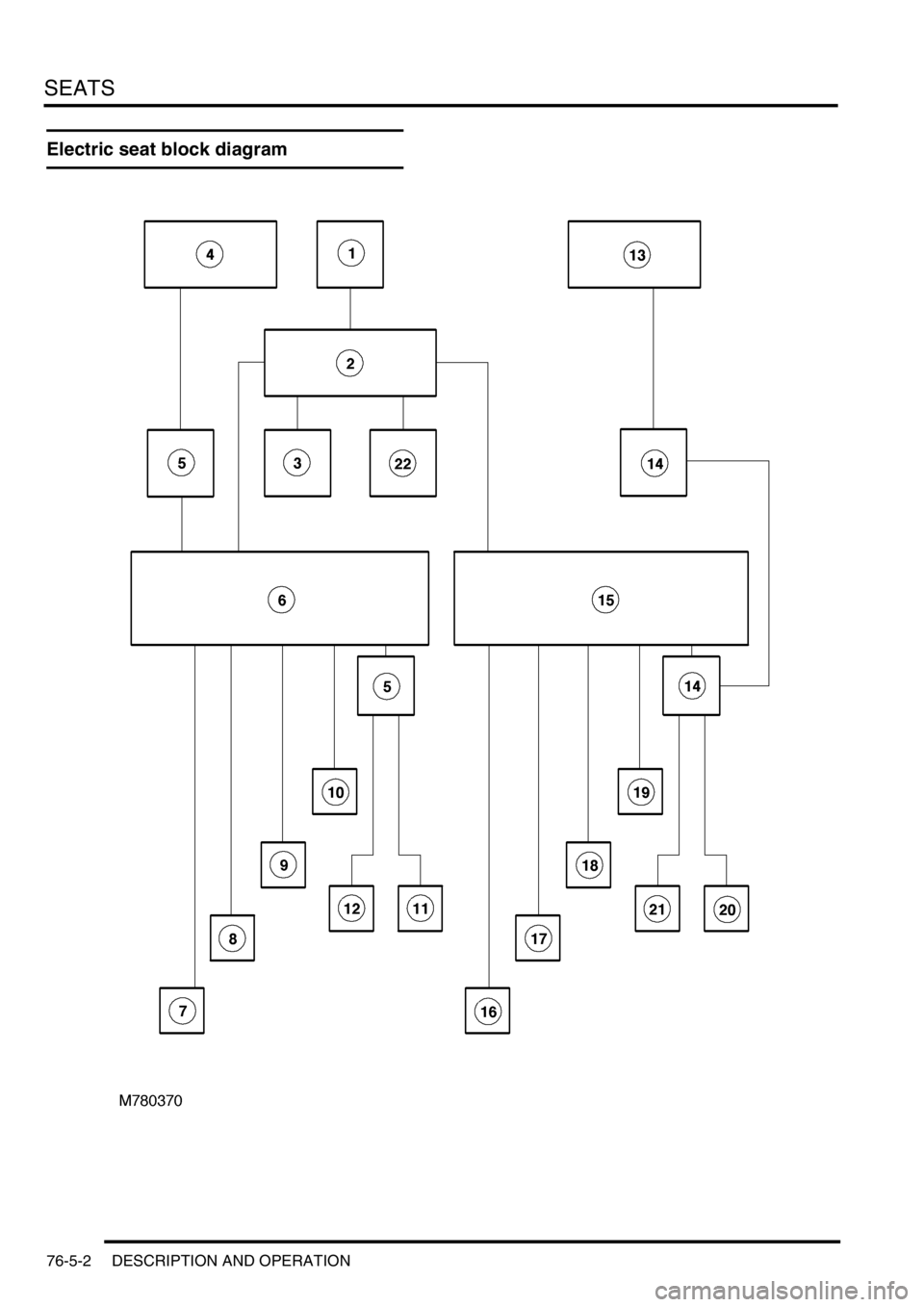
Electric seat block diagram
Page 1195 of 1672

SEATS
76-5-10 DESCRIPTION AND OPERATION
Heated seat block diagram (electric
seats)
1Passenger compartment fuse box
2Left seat heater switch
3Left seat heater module
4Left seat cushion heater element
5Left seat squab heater element
6Right seat heater switch
7Right seat heater module
8Right seat cushion heater element
9Right seat squab heater element
Page 1210 of 1672

SEATS
REPAIRS 76-5-25
Cover - squab - front seat
$% 78.90.08/81
Remove
1.Remove front seat.
+ SEATS, REPAIRS, Seat - front.
2.Place seat on a suitable work bench.
3.Tighten arm rest adjuster fully clockwise and
remove screw cover.
4.Remove screw securing arm rest to seat and
remove arm rest.
5.Remove 2 screws securing outer edge trim
casing to seat frame.
6.Remove trim casing.
7.Release inner edge of trim casing from seat
frame.
8.Remove trim casing. 9.Position seat upside down on table.
10.Release clip securing lower edge of squab
cover to seat frame.
11.Remove 2 clips securing either end of cover to
squab frame.
12.Position seat in upright position.
13.Raise headrest to maximum height.
14.Turn both guides through 90
°.
15.Remove headrest from seat.
16.Remove screws securing grab handles to seat
frame and remove grab handles.
Page 1219 of 1672

SUNROOF
76-6-4 DESCRIPTION AND OPERATION
System block diagram
1Passenger compartment fuse box
2BCU
3Sunroof ECU
4Front sunroof switch
5Front sunroof motor and microswitch
6Rear sunroof - front switch
7Rear sunroof isolation switch
8Rear sunroof - rear switch
9Rear sunroof motor and microswitch
Page 1240 of 1672
CHASSIS AND BODY DIMENSIONS
BODY DIMENSIONS 77-1-7
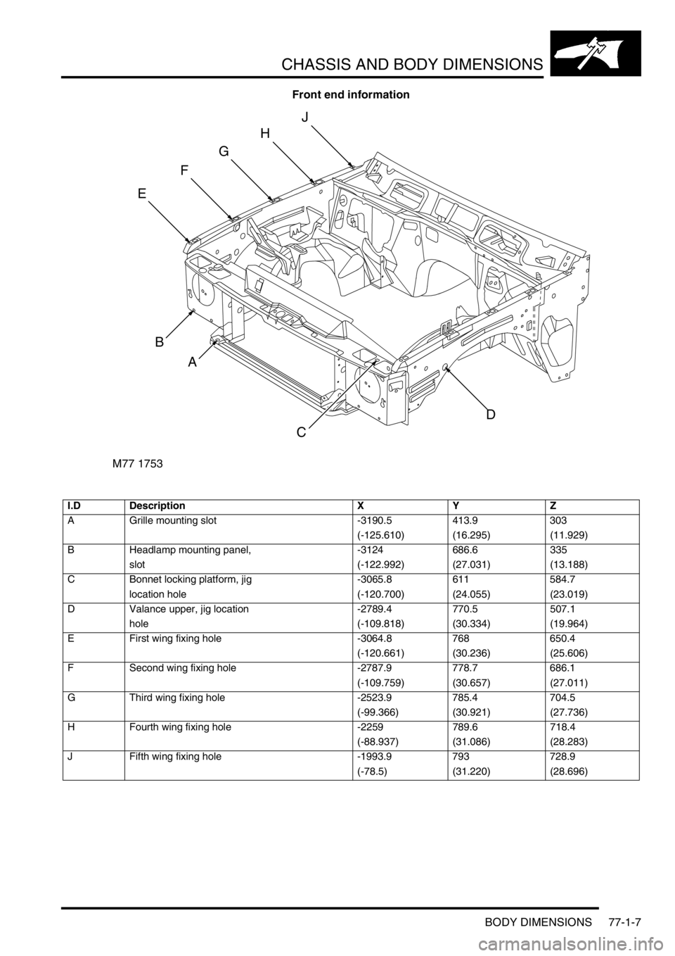
Front end information
I.D Description X Y Z
A Grille mounting slot -3190.5 413.9 303
(-125.610) (16.295) (11.929)
B Headlamp mounting panel, -3124 686.6 335
slot (-122.992) (27.031) (13.188)
C Bonnet locking platform, jig -3065.8 611 584.7
location hole (-120.700) (24.055) (23.019)
D Valance upper, jig location -2789.4 770.5 507.1
hole (-109.818) (30.334) (19.964)
E First wing fixing hole -3064.8 768 650.4
(-120.661) (30.236) (25.606)
F Second wing fixing hole -2787.9 778.7 686.1
(-109.759) (30.657) (27.011)
G Third wing fixing hole -2523.9 785.4 704.5
(-99.366) (30.921) (27.736)
H Fourth wing fixing hole -2259 789.6 718.4
(-88.937) (31.086) (28.283)
J Fifth wing fixing hole -1993.9 793 728.9
(-78.5) (31.220) (28.696)
M77 1753
B
C
D
E
F
G
H
J
A
Page 1242 of 1672
CHASSIS AND BODY DIMENSIONS
BODY DIMENSIONS 77-1-9
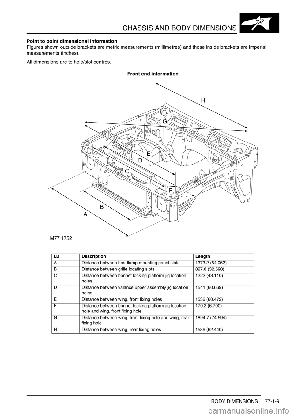
Point to point dimensional information
Figures shown outside brackets are metric measurements (millimetres) and those inside brackets are imperial
measurements (inches).
All dimensions are to hole/slot centres.
Front end information
I.D Description Length
A Distance between headlamp mounting panel slots 1373.2 (54.062)
B Distance between grille locating slots 827.8 (32.590)
C Distance between bonnet locking platform jig location
holes1222 (48.110)
D Distance between valance upper assembly jig location
holes1541 (60.669)
E Distance between wing, front fixing holes 1536 (60.472)
F Distance between bonnet locking platform jig location
hole and wing, front fixing hole170.2 (6.700)
G Distance between wing, front fixing hole and wing, rear
fixing hole1894.7 (74.594)
H Distance between wing, rear fixing holes 1586 (62.440)
M77 1752
A
B
C
D
E
F
G
H
Page 1245 of 1672

CHASSIS AND BODY DIMENSIONS
77-1-12 BODY DIMENSIONS
Rear end information
I.D Description Length
A Distance between taildoor setting block, jig location hole
and taildoor bottom hinge, middle fixing hole1364.4 (53.716)
B Distance between taildoor setting block, jig location hole
and taildoor top hinge, middle fixing hole1319.8 (51.960)
C Distance between crossmember outer rear panel, jig
location hole and rear headrest fixing hole 1413 (55.629)
M77 1758A
A
B
C
Page 1251 of 1672
PANEL REPAIRS
77-2-2 REPLACEMENT PANELS
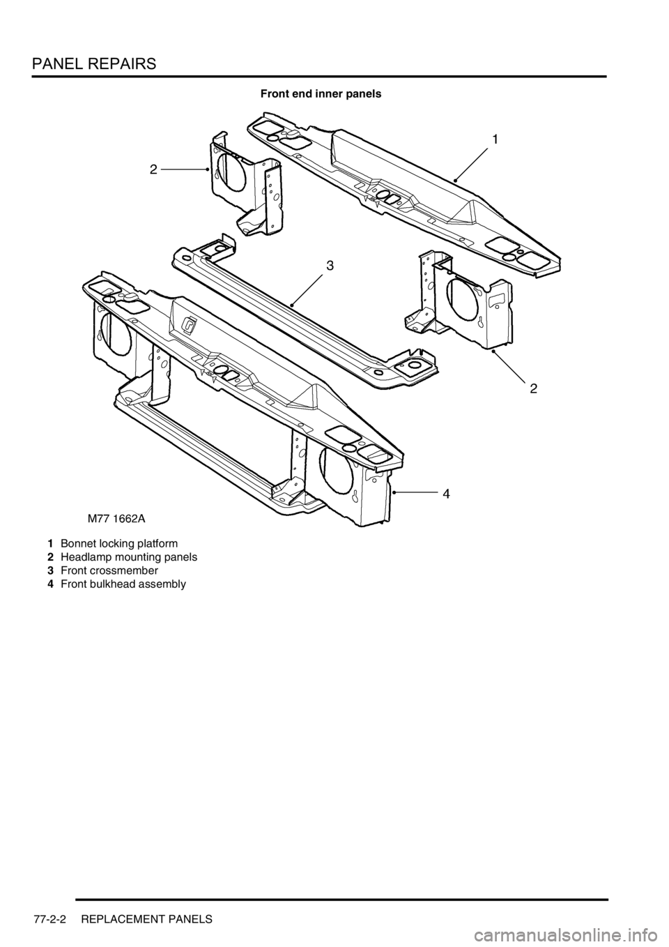
Front end inner panels
1Bonnet locking platform
2Headlamp mounting panels
3Front crossmember
4Front bulkhead assembly
Page 1265 of 1672
PANEL REPAIRS
77-2-16 PROCEDURES
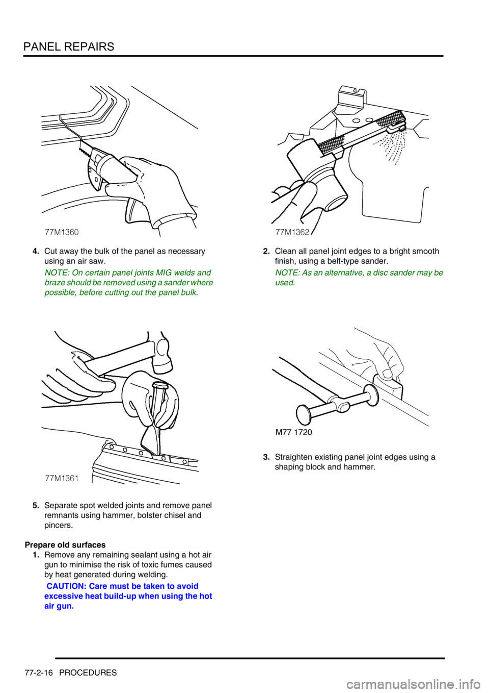
4.Cut away the bulk of the panel as necessary
using an air saw.
NOTE: On certain panel joints MIG welds and
braze should be removed using a sander where
possible, before cutting out the panel bulk.
5.Separate spot welded joints and remove panel
remnants using hammer, bolster chisel and
pincers.
Prepare old surfaces
1.Remove any remaining sealant using a hot air
gun to minimise the risk of toxic fumes caused
by heat generated during welding.
CAUTION: Care must be taken to avoid
excessive heat build-up when using the hot
air gun.2.Clean all panel joint edges to a bright smooth
finish, using a belt-type sander.
NOTE: As an alternative, a disc sander may be
used.
3.Straighten existing panel joint edges using a
shaping block and hammer.
Page 1270 of 1672
PANEL REPAIRS
REPAIRS 77-2-21
REPAIRS
Front bulkhead assembly
Remove
1.Disconnect both battery leads, negative lead
first.
2.Disconnect leads/multiplug from alternator.
3.Remove front wing.
+ EXTERIOR FITTINGS, REPAIRS,
Wing - front - up to 03MY.
4.Remove washer reservoir.
+ WIPERS AND WASHERS, REPAIRS,
Reservoir - washer - up to 03MY.
5. Models with A/C: Remove condensor.
+ AIR CONDITIONING, REPAIRS,
Condenser.
6. Diesel models: Remove gearbox fluid cooler.
7.Remove RH and LH headlamps.
+ LIGHTING, REPAIRS, Headlamp - up
to 03MY.
8.Release headlamp levelling motors and
position aside.
9.Release headlamp wiring and position aside.
10.Remove battery.
+ CHARGING AND STARTING,
REPAIRS, Battery.
11.Remove battery tray.
12.Remove air filter assembly.
+ ENGINE MANAGEMENT SYSTEM -
Td5, REPAIRS, Air filter assembly.
+ ENGINE MANAGEMENT SYSTEM -
V8, REPAIRS, Air cleaner assembly.
13.Remove 2 earth leads from LH of front
bulkhead.
14.Remove RH horn.
+ ALARM SYSTEM AND HORN,
REPAIR, Vehicle horn.
15. Models with A/C: Release and remove A/C
pipes.
16.Remove RH and LH crush cans.
17.Remove bonnet release cable.
18.Support bonnet in open position
19.Remove bonnet locking mechanism.
20.Remove VIN plate.
21.Remove 2 bolts securing front bulkhead
assembly to chassis.
22.Remove centre braces.Repair
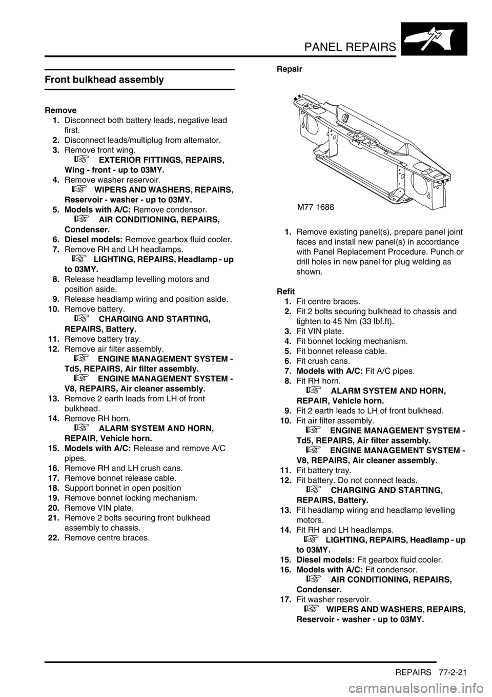
1.Remove existing panel(s), prepare panel joint
faces and install new panel(s) in accordance
with Panel Replacement Procedure. Punch or
drill holes in new panel for plug welding as
shown.
Refit
1.Fit centre braces.
2.Fit 2 bolts securing bulkhead to chassis and
tighten to 45 Nm (33 lbf.ft).
3.Fit VIN plate.
4.Fit bonnet locking mechanism.
5.Fit bonnet release cable.
6.Fit crush cans.
7. Models with A/C: Fit A/C pipes.
8.Fit RH horn.
+ ALARM SYSTEM AND HORN,
REPAIR, Vehicle horn.
9.Fit 2 earth leads to LH of front bulkhead.
10.Fit air filter assembly.
+ ENGINE MANAGEMENT SYSTEM -
Td5, REPAIRS, Air filter assembly.
+ ENGINE MANAGEMENT SYSTEM -
V8, REPAIRS, Air cleaner assembly.
11.Fit battery tray.
12.Fit battery. Do not connect leads.
+ CHARGING AND STARTING,
REPAIRS, Battery.
13.Fit headlamp wiring and headlamp levelling
motors.
14.Fit RH and LH headlamps.
+ LIGHTING, REPAIRS, Headlamp - up
to 03MY.
15. Diesel models: Fit gearbox fluid cooler.
16. Models with A/C: Fit condensor.
+ AIR CONDITIONING, REPAIRS,
Condenser.
17.Fit washer reservoir.
+ WIPERS AND WASHERS, REPAIRS,
Reservoir - washer - up to 03MY.