reset LAND ROVER DISCOVERY 2002 Workshop Manual
[x] Cancel search | Manufacturer: LAND ROVER, Model Year: 2002, Model line: DISCOVERY, Model: LAND ROVER DISCOVERY 2002Pages: 1672, PDF Size: 46.1 MB
Page 375 of 1672

EMISSION CONTROL - V8
17-2-38 DESCRIPTION AND OPERATION
Evaporative emission control operation
Fuel vapour is stored in the activated charcoal (EVAP) canister for retention when the vehicle is not operating. When
the vehicle is operating, fuel vapour is drawn from the canister into the engine via a purge control valve. The vapour
is then delivered to the intake plenum chamber to be supplied to the engine cylinders where it is burned in the
combustion process.
During fuel filling the fuel vapour displaced from the fuel tank is allowed to escape to atmosphere, valves within the
fuel filler prevent any vapour escaping through to the EVAP canister as this can adversely affect the fuel cut-off height.
Only fuel vapour generated whilst driving is prevented from escaping to atmosphere by absorption into the charcoal
canister. The fuel filler shuts off to leave the tank approximately 10% empty to ensure the ROVs are always above
the fuel level and so vapour can escape to the EVAP canister and the tank can breathe. The back pressures normally
generated during fuel filling are too low to open the pressure relief valve, but vapour pressures accumulated during
driving are higher and can open the pressure relief valve. Should the vehicle be overturned, the ROVs shut off to
prevent any fuel spillage.
Fuel vapour generated from within the fuel tank as the fuel heats up is stored in the tank until the pressure exceeds
the operating pressure of the two-way valve. When the two-way valve opens, the fuel vapour passes along the vent
line from the fuel tank (via the fuel tank vapour separator) to the evaporation inlet port of the EVAP canister. The fuel
tank vents between 5.17 and 6.9 kPa.
Fuel vapour evaporating from the fuel tank is routed to the EVAP canister through the fuel vapour separator and vent
line. Liquid fuel must not be allowed to contaminate the charcoal in the EVAP canister. To prevent this, the fuel vapour
separator fitted to the fuel neck allows fuel to drain back into the tank. As the fuel vapour cools, it condenses and is
allowed to flow back into the fuel tank from the vent line by way of the two-way valve.
The EVAP canister contains charcoal which absorbs and stores fuel vapour from the fuel tank while the engine is not
running. When the canister is not being purged, the fuel vapour remains in the canister and clean air exits the canister
via the air inlet port.
The engine management ECM controls the electrical output signal to the purge valve. The system will not work
properly if there is leakage or clogging within the system or if the purge valve cannot be controlled.
+ ENGINE MANAGEMENT SYSTEM - V8, DESCRIPTION AND OPERATION, Description - engine
management.
When the engine is running, the ECM decides when conditions are correct for vapour to be purged from the EVAP
canister and opens the canister purge valve. This connects a manifold vacuum line to the canister and fuel vapour
containing the hydrocarbons is drawn from the canister's charcoal element to be burned in the engine. Clean air is
drawn into the canister through the atmosphere vent port to fill the displaced volume of vapour.
The purge valve remains closed below preset coolant and engine speed values to protect the engine tune and
catalytic converter performance. If the EVAP canister was purged during cold running or at idling speed, the additional
enrichment in the fuel mixture would delay the catalytic converter light off time and cause erratic idle. When the purge
valve is opened, fuel vapour from the EVAP canister is drawn into the plenum chamber downside of the throttle
housing, to be delivered to the combustion chambers for burning.
The purge valve is opened and closed in accordance with a pulse width modulated (PWM) signal supplied from the
engine management ECM. The system will not work properly if the purge valve cannot be controlled. Possible failure
modes associated with the purge valve are listed below:
lValve drive open circuit.
lShort circuit to vehicle supply or ground.
lPurge valve or pipework blocked or restricted.
lPurge valve stuck open.
lPipework joints leaking or disconnected.
Page 411 of 1672

ENGINE MANAGEMENT SYSTEM - TD5
18-1-18 DESCRIPTION AND OPERATION
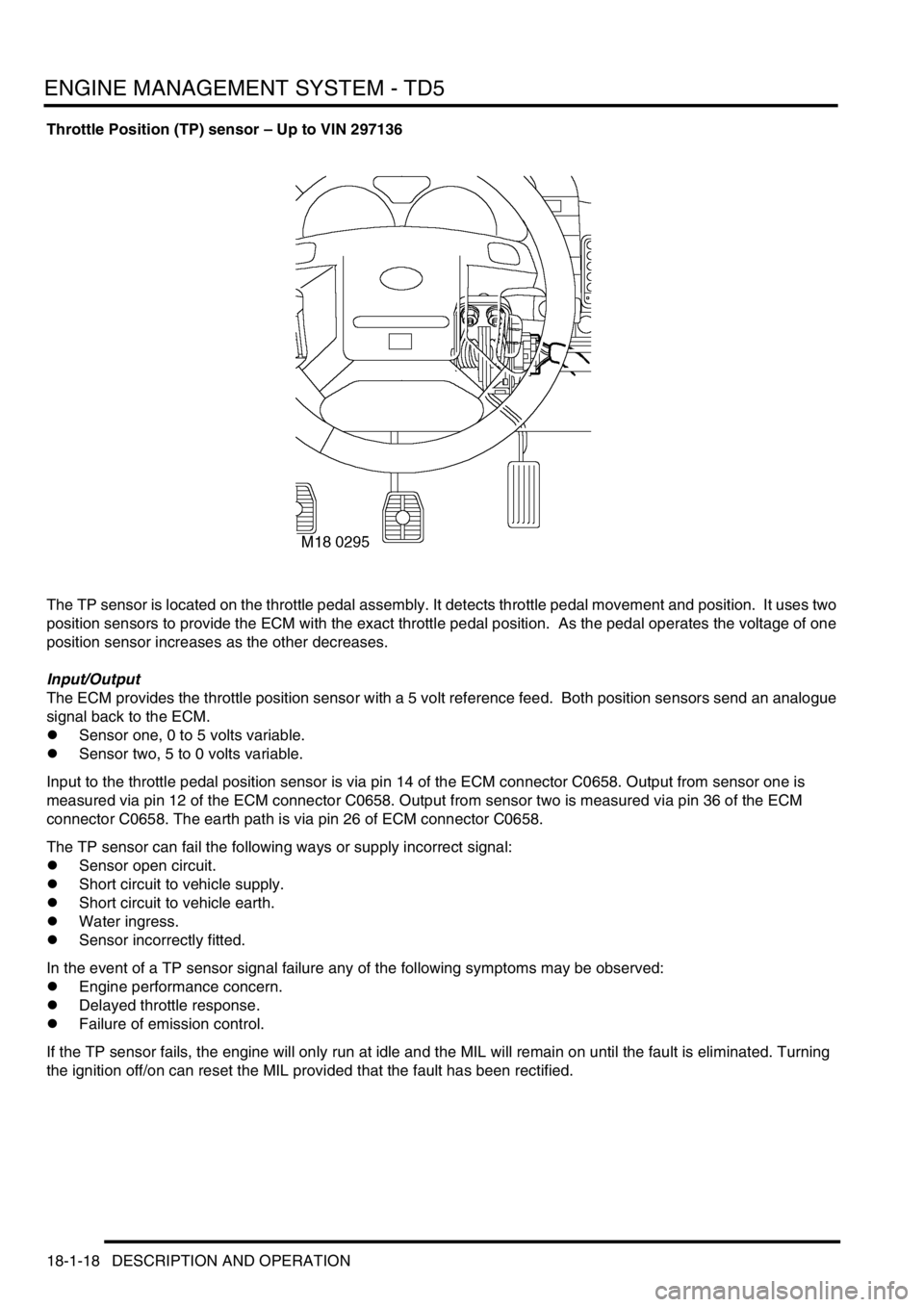
Throttle Position (TP) sensor – Up to VIN 297136
The TP sensor is located on the throttle pedal assembly. It detects throttle pedal movement and position. It uses two
position sensors to provide the ECM with the exact throttle pedal position. As the pedal operates the voltage of one
position sensor increases as the other decreases.
Input/Output
The ECM provides the throttle position sensor with a 5 volt reference feed. Both position sensors send an analogue
signal back to the ECM.
lSensor one, 0 to 5 volts variable.
lSensor two, 5 to 0 volts variable.
Input to the throttle pedal position sensor is via pin 14 of the ECM connector C0658. Output from sensor one is
measured via pin 12 of the ECM connector C0658. Output from sensor two is measured via pin 36 of the ECM
connector C0658. The earth path is via pin 26 of ECM connector C0658.
The TP sensor can fail the following ways or supply incorrect signal:
lSensor open circuit.
lShort circuit to vehicle supply.
lShort circuit to vehicle earth.
lWater ingress.
lSensor incorrectly fitted.
In the event of a TP sensor signal failure any of the following symptoms may be observed:
lEngine performance concern.
lDelayed throttle response.
lFailure of emission control.
If the TP sensor fails, the engine will only run at idle and the MIL will remain on until the fault is eliminated. Turning
the ignition off/on can reset the MIL provided that the fault has been rectified.
Page 471 of 1672

ENGINE MANAGEMENT SYSTEM - V8
18-2-14 DESCRIPTION AND OPERATION
In the event of a CKP sensor signal failure any of the following symptoms may be observed:
lEngine cranks but fails to start.
lMIL remains on at all times.
lEngine misfires (CKP sensor incorrectly fitted).
lEngine runs roughly or even stalls (CKP sensor incorrectly fitted).
lTachometer fails to work.
lFlywheel adaption reset – ferrous contamination
If the CKP sensor fails while the engine is running the engine will suddenly stall, this is because the CKP sensor has
no backup strategy. If this happens the ECM will produce a fault code that it can store in its memory. If the engine is
not running when the CKP sensor fails, the vehicle will crank but will be unlikely to start, and no fault code will be
generated. In this instance the MIL lamp will remain illuminated and the tachometer will fail to read.
It is vital that the CKP sensor output wires are not reversed (i.e. the connector is fitted incorrectly) as this will cause
a 3
° advance in ignition timing. This happens because the ECM uses the falling edge of the signal waveform as its
reference or timing point for each passing tooth on the reluctor.
Whenever a new crankshaft position sensor is fitted or the flywheel is removed, the adaptive values will have to be
reset, using TestBook.
Should a malfunction of the component occur, the following fault codes may be evident and can be retrieved by
TestBook:
Camshaft Position (CMP) sensor (C0176)
The CMP sensor is located on the front of the engine, above and behind the crankshaft pulley. The CMP sensor is a
Hall effect sensor producing four pulses for every two crankshaft revolutions. The sensor is positioned close to the
camshaft gear wheel, the gear wheel has four slots machined at 90
° intervals. This allows the ECM to recognise 4
individual cylinders every camshaft revolution or all 8 cylinders every crankshaft revolution.
The CMP sensor Hall effect works as a magnetic switch. It switches battery voltage on or off depending on the position
of the camshaft gear wheel in relationship to the sensor.
The ECM uses this signal for cylinder recognition to control sequential fuel injection, engine knock and diagnostic
purposes.
P Code J2012 description Land Rover description
P0335 Crankshaft position sensor a circuit malfunction Reference mark outside search window for more than
two revs, with engine speed above 500 rev/min
P0336 Crankshaft position sensor a circuit range/
performanceIncorrect number of teeth detected ±1 tooth between
reference marks with engine speed above 500 rpm
Page 495 of 1672

ENGINE MANAGEMENT SYSTEM - V8
18-2-38 DESCRIPTION AND OPERATION
Spark plugs
The spark plugs are platinum tipped on both centre and earth electrodes. The platinum tips give a long maintenance
free life.
Cleaning or resetting the spark plug gap is not recommended as this could result in damaging the platinum tips and
thereby reducing reliability.
The misfire detection system will malfunction and store erroneous codes if the incorrect spark plugs are used.
Input/Output
The ignition coils provide a voltage to the spark plugs via the ht leads. The cylinder head via the individual thread of
each spark plug provides the earth path.
The spark plugs can fail in the following ways:
lFaulty component.
lConnector or wiring fault.
lBreakdown of high tension lead causing tracking to chassis earth.
lIncorrect spark plugs fitted.
In the event of a spark plug failure, misfire on specific cylinder may be observed:
High tension (ht) leads
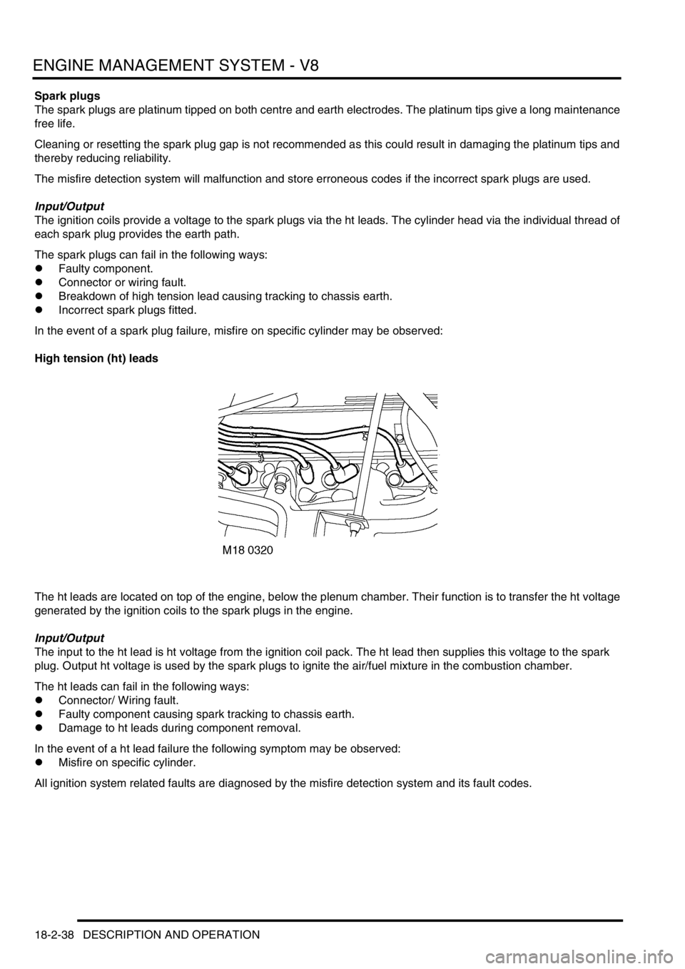
The ht leads are located on top of the engine, below the plenum chamber. Their function is to transfer the ht voltage
generated by the ignition coils to the spark plugs in the engine.
Input/Output
The input to the ht lead is ht voltage from the ignition coil pack. The ht lead then supplies this voltage to the spark
plug. Output ht voltage is used by the spark plugs to ignite the air/fuel mixture in the combustion chamber.
The ht leads can fail in the following ways:
lConnector/ Wiring fault.
lFaulty component causing spark tracking to chassis earth.
lDamage to ht leads during component removal.
In the event of a ht lead failure the following symptom may be observed:
lMisfire on specific cylinder.
All ignition system related faults are diagnosed by the misfire detection system and its fault codes.
Page 506 of 1672

ENGINE MANAGEMENT SYSTEM - V8
DESCRIPTION AND OPERATION 18-2-49
TestBook is able to retrieve the following Catalyst damage fault codes:
The flywheel/ reluctor ring adaptions must be reset if the CKP sensor or the flywheel are changed.
Vehicle Speed Signal (VSS)
The VSS is used, by the ECM, to control idle speed and overrun cut off. The ECM receives the signal through a hard
wired connection direct from the SLABS ECU.
For vehicles fitted with an automatic gearbox, two vehicle speed signals are received by the ECM. The second signal
is derived from the main gearbox output shaft speed, and is sent to the ECM by the Electronic Automatic Transmission
(EAT) ECU though the Controller Area Network (CAN). The ECM compares the vehicle speed signal generated by
the SLABS ECU with that supplied via the CAN.
The ECM also receives transfer box information. This allows the ECM to take in to account the vehicle being driven
using low range gearing and compensate as necessary.
On vehicles with manual transmission, the SLABS signal is checked against a threshold value stored in ECM memory.
If other engine parameters indicate the engine is at high load and the VSS is below the threshold, a fault condition is
registered in the diagnostic memory.
The vehicle speed signal generated by the SLABS ECU is in the form of a pulse width modulated signal (PWM).
Pulses are generated at 8000 per mile, and the frequency of the signal changes in accordance with road speed. At
zero road speed the ECU outputs a reference signal at a frequency of 2Hz for diagnostic purposes.
Function
The input signal for the SLABS ECU is measured via pin 22 of connector C0637 of the ECM. The SLABS ECU
generates a PWM signal switching between 0 and 12 volts at a frequency of 8000 pulses per mile. For vehicles with
automatic gearbox the input signal for the EAT ECU is measured via pins 36 and 37 of connector C0637 of the ECM.
These pin numbers provide a bi-directional communications link using the CAN data bus.
P Code J2012 Description Land Rover Description
P1300 Misfire detected sufficient to cause catalyst
damageCatalyst damaging level of misfire on more than one
cylinder
P1301 No description Catalyst damaging level of misfire detected on cylinder
No.1
P1302 No description Catalyst damaging level of misfire detected on cylinder
No.2
P1303 No description Catalyst damaging level of misfire detected on cylinder
No.3
P1304 No description Catalyst damaging level of misfire detected on cylinder
No.4
P1305 No description Catalyst damaging level of misfire detected on cylinder
No.5
P1306 No description Catalyst damaging level of misfire detected on cylinder
No.6
P1307 No description Catalyst damaging level of misfire detected on cylinder
No.7
P1308 No description Catalyst damaging level of misfire detected on cylinder
No.8
Page 530 of 1672

ENGINE MANAGEMENT SYSTEM - V8
REPAIRS 18-2-73
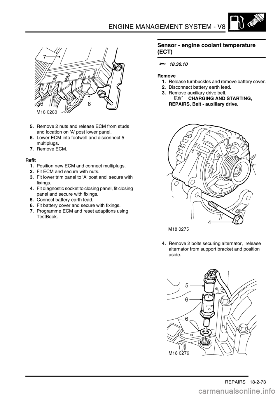
5.Remove 2 nuts and release ECM from studs
and location on 'A' post lower panel.
6.Lower ECM into footwell and disconnect 5
multiplugs.
7.Remove ECM.
Refit
1.Position new ECM and connect multiplugs.
2.Fit ECM and secure with nuts.
3.Fit lower trim panel to 'A' post and secure with
fixings.
4.Fit diagnostic socket to closing panel, fit closing
panel and secure with fixings.
5.Connect battery earth lead.
6.Fit battery cover and secure with fixings.
7.Programme ECM and reset adaptions using
TestBook.
Sensor - engine coolant temperature
(ECT)
$% 18.30.10
Remove
1.Release turnbuckles and remove battery cover.
2.Disconnect battery earth lead.
3.Remove auxiliary drive belt.
+ CHARGING AND STARTING,
REPAIRS, Belt - auxiliary drive.
4.Remove 2 bolts securing alternator, release
alternator from support bracket and position
aside.
Page 532 of 1672

ENGINE MANAGEMENT SYSTEM - V8
REPAIRS 18-2-75
4.Fit CKP sensor heat shield and secure with
bolts.
5.Fit underbelly panel and secure with fixings.
6.Remove stand(s) and lower vehicle.
7.Connect battery earth lead.
8.Fit battery cover and secure the fixings.
9.Reset adaptions using TestBook.
Sensor - radiator temperature
$% 18.30.20
Remove
1.Disconnect battery earth lead.
2.Position container to collect coolant spillage.
3.Disconnect multiplug from sensor.
4.Remove sensor and discard sealing washer.
Refit
1.Fit new sealing washer to sensor.
2.Fit and tighten sensor.
3.Connect multiplug to sensor.
4.Refill cooling system.
5.Connect battery earth lead.
Page 556 of 1672

FUEL DELIVERY SYSTEM - TD5
DESCRIPTION AND OPERATION 19-1-11
Operation
When the ignition switch is moved to position II, the fuel pump relay in the engine compartment fusebox is energised
by the ECM. Battery voltage is supplied from the fuel pump relay to the fuel pump which operates. If engine cranking
is not detected by the ECM within a three minute period, the ECM will 'time-out', de-energising the fuel pump relay.
When the ignition is turned off the ECM timer will reset.
The low pressure stage of the fuel pump draws fuel from the swirl pot and pumps it into the fuel filter. The high
pressure stage of the fuel pump draws the fuel from the fuel filter and pumps it along the fuel feed pipe to the cylinder
head.
The fuel enters the cylinder head through a connection on the fuel pressure regulator housing and supplies each
injector with pressurised fuel. The fuel pressure regulator maintains the fuel pressure at the injectors at 4 bar (58
lbf.in
2) by returning excess fuel back to the fuel filter. The returned fuel passes through the fuel cooler in the engine
compartment before it passes to the fuel filter.
When the engine is running, each injector is operated by an overhead camshaft which depresses a push rod in each
injector at a timed interval. When the cam has depressed the push rod and the push rod is returning to its extended
position, fuel is drawn from the fuel supply drilling into the injector.
When the ECM determines that injection is required, the ECM transmits an electrical pulse which energises the fast
acting solenoid, closing the spill valve on the injector and locking fuel in the injector body. As the cam begins to
depress the push rod, the fuel in the injector is rapidly pressurised. When the pressure exceeds the nozzle spring
pressure, the nozzle opens and injects fuel at very high pressure into the cylinder.
When the ECM determines that the injection period should end, the solenoid is rapidly de-energised, opening the spill
valve on the injector and allowing fuel to pass into the return circuit.
The ECM controls the injection timing by altering the time at which the solenoid is energised and the injection period
by controlling the period for which the solenoid is energised.
Page 810 of 1672

AUTOMATIC GEARBOX - ZF4HP22 - 24
DESCRIPTION AND OPERATION 44-13
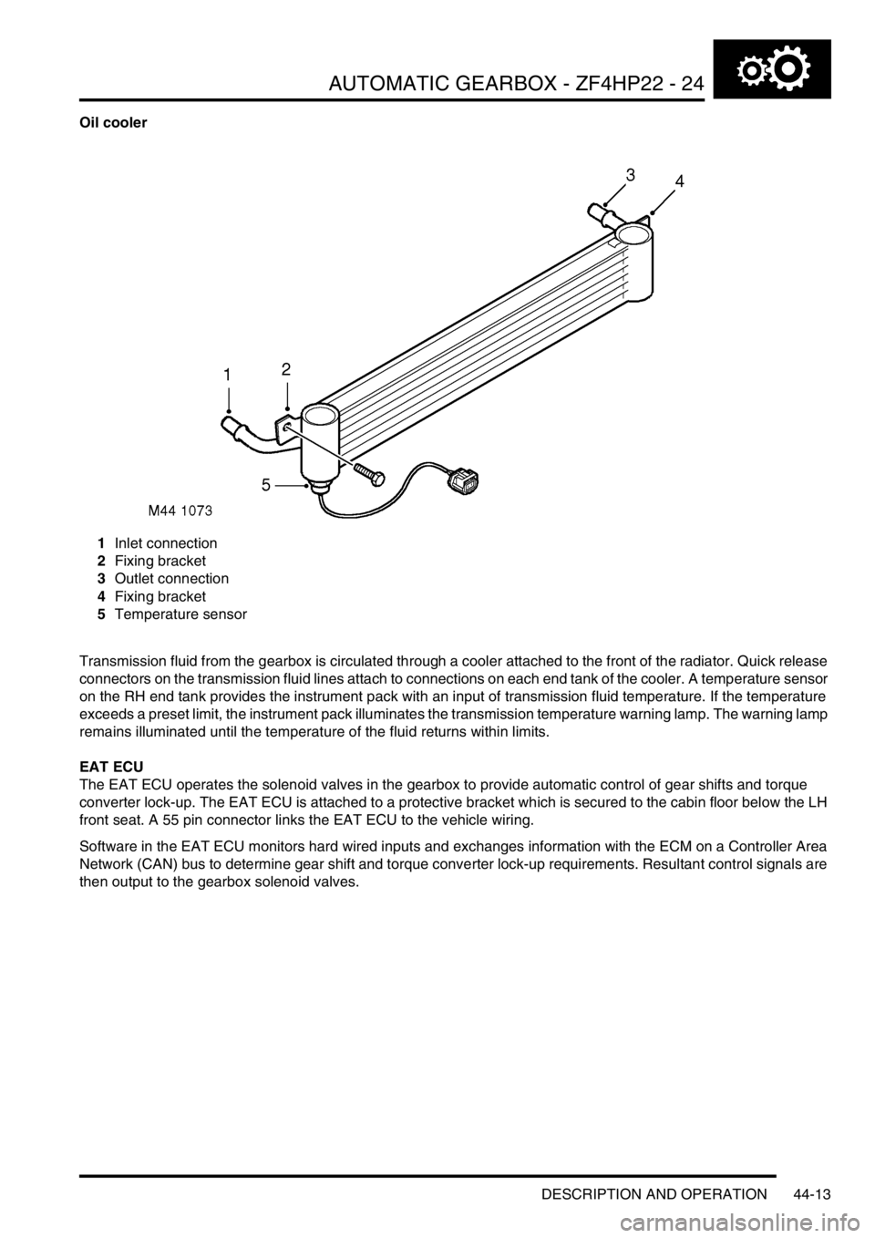
Oil cooler
1Inlet connection
2Fixing bracket
3Outlet connection
4Fixing bracket
5Temperature sensor
Transmission fluid from the gearbox is circulated through a cooler attached to the front of the radiator. Quick release
connectors on the transmission fluid lines attach to connections on each end tank of the cooler. A temperature sensor
on the RH end tank provides the instrument pack with an input of transmission fluid temperature. If the temperature
exceeds a preset limit, the instrument pack illuminates the transmission temperature warning lamp. The warning lamp
remains illuminated until the temperature of the fluid returns within limits.
EAT ECU
The EAT ECU operates the solenoid valves in the gearbox to provide automatic control of gear shifts and torque
converter lock-up. The EAT ECU is attached to a protective bracket which is secured to the cabin floor below the LH
front seat. A 55 pin connector links the EAT ECU to the vehicle wiring.
Software in the EAT ECU monitors hard wired inputs and exchanges information with the ECM on a Controller Area
Network (CAN) bus to determine gear shift and torque converter lock-up requirements. Resultant control signals are
then output to the gearbox solenoid valves.
Page 815 of 1672

AUTOMATIC GEARBOX - ZF4HP22 - 24
44-18 DESCRIPTION AND OPERATION
With time, the components in a gearbox wear and the duration of the gear shifts tends to increase, which has an
adverse effect on the brake clutches. To counteract this, the EAT ECU applies a pressure adaptation to each shift.
To calculate the adaptations, the EAT ECU monitors the pressure modulation used, and time taken, for each shift. If
a subsequent shift of the same type, in terms of throttle position and engine speed, has a longer duration, the EAT
ECU stores an adaptation for that type of shift in a volatile memory. The adaptation is then included in future pressure
calculations for that type of shift, to restore shift duration to the nominal.
Kickdown
The EAT ECU monitors the input of the throttle position sensor to determine when kickdown is required. When it
detects a kickdown situation, the EAT ECU immediately initiates a down shift provided the target gear will not cause
the engine speed limit to be exceeded.
Torque converter lock-up
The EAT ECU energises the lock-up solenoid valve to engage the lock-up clutch. Lock-up clutch operation is
dependent on throttle position, engine speed, operating mode and the range selected on the transfer box.
High range
Unique lock-up maps, similar to the shift maps, are incorporated in the economy and sport modes for all forward gears.
Engagement and disengagement of the lock-up clutch is dependent on throttle position and engine speed.
Low range
To enhance off road control, particularly when manoeuvring at low speeds, torque converter lock-up does not occur
when there is any degree of throttle opening. When the throttle is closed above a preset engine speed, the lock-up
clutch engages to provide maximum engine braking.
Increased load/reduced torque compensation
To aid performance and driveability in the high range economy mode, the EAT ECU has three adaptive shift and lock-
up maps. These maps delay upshifts and torque converter lock-up similar to the sport mode if the inputs from the
engine indicate:
lA sustained high load on the engine, such as occurs when the vehicle is ascending a steep gradient or towing a
trailer.
lA lower than normal engine torque, such as occurs at altitude or high ambient temperatures.
The EAT ECU monitors the engine inputs and selects the most appropriate adaptive map for the prevailing conditions.
Diagnostics
While the ignition is on, the EAT ECU diagnoses the system for faults. The extent of the diagnostic capability at any
particular time depends on the prevailing operating conditions, e.g. it is not possible to check torque converter lock-
up while the vehicle is stationary, or to check for a short circuit to earth if the circuit concerned is already at a low
potential.
If a fault is detected, the EAT ECU immediately stores a fault code and the values of three operating parameters
associated with the fault. Depending on the fault, there are four possible effects:
lThe fault has little effect on gearbox operation or vehicle emissions. The driver will probably not notice any
change and the warning lamps remain extinguished.
lThe fault has little effect on gearbox operation but may effect vehicle emissions. On NAS vehicles, if the fault is
detected on a second consecutive drive cycle, the MIL illuminates.
lAll gears are available but kickdown does not function. The sport and manual warning lamps flash. The MIL
remains extinguished.
lLimp home mode is selected and vehicle performance is greatly reduced. The sport and manual warning lamps
flash. In all markets, if the fault is detected on a second consecutive drive cycle, the MIL illuminates.