remote control LAND ROVER DISCOVERY 2002 Owner's Guide
[x] Cancel search | Manufacturer: LAND ROVER, Model Year: 2002, Model line: DISCOVERY, Model: LAND ROVER DISCOVERY 2002Pages: 1672, PDF Size: 46.1 MB
Page 1514 of 1672

ALARM SYSTEM AND HORN
DESCRIPTION AND OPERATION 86-4-5
Description
General
The anti-theft system deters the theft of the vehicle with both active and passive systems. The active systems monitor
the vehicle perimeter and, in some markets the vehicle interior, for intrusion. If the system detects intrusion, an alarm
sounds. The passive systems include a vehicle immobiliser as well as protection against intrusion through super
locking the doors. The vehicle is immobilised whenever the ignition key is removed from the ignition switch. Super
locking prevents the interior door handles from opening the doors. In addition, there are many features and functions
that enhance system operation.
It is possible to perform the various functions associated with the anti-theft system remotely. To accomplish this, the
handset generates a radio frequency when the lock button or unlock button is depressed. This signal is transmitted
to the Body Control Unit (BCU) via a receiver located in front of rear sunroof beneath the headlining. Precise alignment
of the handset to the receiver is not necessary. The approximate operating range between the handset and the
receiver is 10 metres (33 feet).
It is important to understand the configuration of the system on each particular vehicle. There are many
different combinations of features with dedicated operating modes. System configuration for each vehicle
can be determined using TestBook.
The anti-theft system is controlled centrally by the BCU, which is located below and behind the passenger glovebox.
A serial communication link communicates between the Intelligent Driver Module (IDM) located within the fusebox,
the BCU and the LED located in the instrument panel.
The state of the alarm is stored in the BCU. If the battery is disconnected while the alarm is armed, the alarm will be
triggered when the battery is reconnected.
NOTE: Disconnecting the battery while the alarm is armed triggers the alarm. Always disarm the alarm system before
disconnecting the battery.
The BCU also receives inputs from the following components:
lIgnition key in sensor.
lIgnition switch.
lFuel cut off switch.
lFuel flap release switch.
The BCU also interacts with the following components:
lStarter relay.
lVehicle horns.
lDirection indicators.
lFuel flap release actuator.
lCourtesy lamps.
Page 1521 of 1672

ALARM SYSTEM AND HORN
86-4-12 DESCRIPTION AND OPERATION
Passive remobilisation exciter coil
The passive remobilisation exciter coil consists of a coil around the steering column lock. The coil energises to create
a magnetic field when the ignition is switched to position II.
This coil activates the handset initiating the mobilisation of the vehicle.
Input/Output
The input to the passive remobilisation exciter coil from the BCU is a 12 volts 125 kHz sinewave. The passive
remobilisation exciter coil also receives an ignition controlled power supply via fuse 20 (15 amperes) located in the
engine compartment fuse box. On receiving these signals, a magnetic field is generated which activates the handset
to produce a remobilisation signal. This remobilisation signal is transmitted to the remote receiver and onto the BCU
to allow the engine to start.
Page 1545 of 1672

WINDOWS
86-5-6 DESCRIPTION AND OPERATION
Front window motors
The front window motors are permanent magnet motors. There is a window motor in each front door. The front
window motors are controlled by the BCU.
The BCU provides both the voltage and the earth paths to the front window motors. The BCU reverses the direction
the window motor operates by switching the voltage and earth paths to the window motor. The BCU also monitors
stall current for the front window motors.
TestBook can operate the front window motors remotely.
Page 1554 of 1672

IN CAR ENTERTAINMENT
DESCRIPTION AND OPERATION 86-6-1
IN CAR ENTERTA INMENT DESCRIPTION AND OPERAT ION
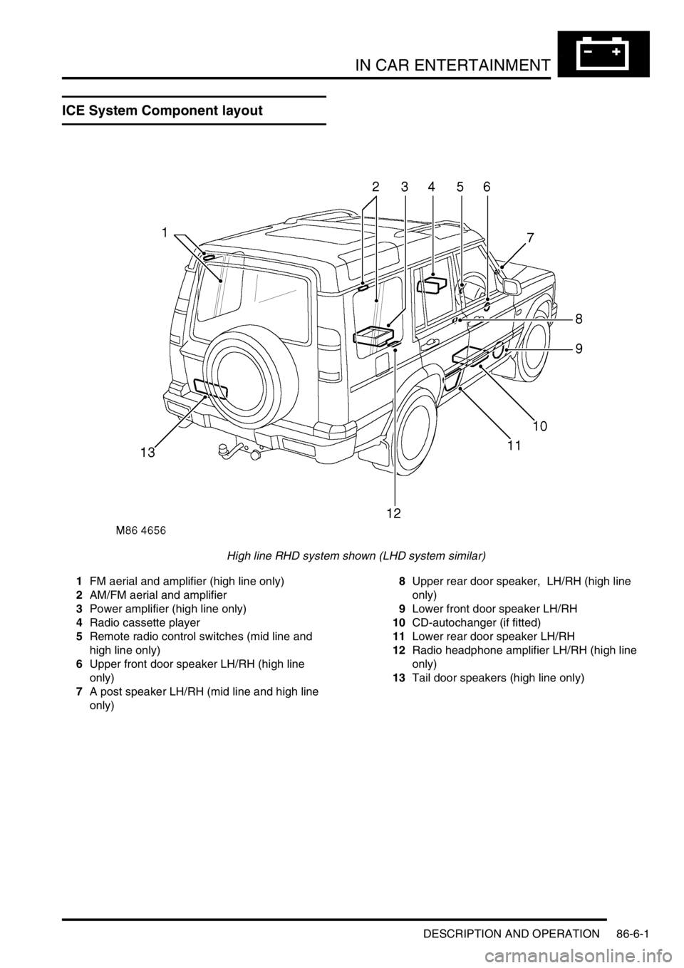
ICE System Component layout
High line RHD system shown (LHD system similar)
1FM aerial and amplifier (high line only)
2AM/FM aerial and amplifier
3Power amplifier (high line only)
4Radio cassette player
5Remote radio control switches (mid line and
high line only)
6Upper front door speaker LH/RH (high line
only)
7A post speaker LH/RH (mid line and high line
only)8Upper rear door speaker, LH/RH (high line
only)
9Lower front door speaker LH/RH
10CD-autochanger (if fitted)
11Lower rear door speaker LH/RH
12Radio headphone amplifier LH/RH (high line
only)
13Tail door speakers (high line only)
Page 1555 of 1672

IN CAR ENTERTAINMENT
86-6-2 DESCRIPTION AND OPERATION
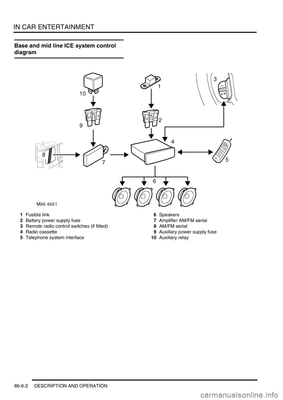
Base and mid line ICE system control
diagram
1Fusible link
2Battery power supply fuse
3Remote radio control switches (if fitted)
4Radio cassette
5Telephone system interface6Speakers
7Amplifier AM/FM aerial
8AM/FM aerial
9Auxiliary power supply fuse
10Auxiliary relay
Page 1556 of 1672

IN CAR ENTERTAINMENT
DESCRIPTION AND OPERATION 86-6-3
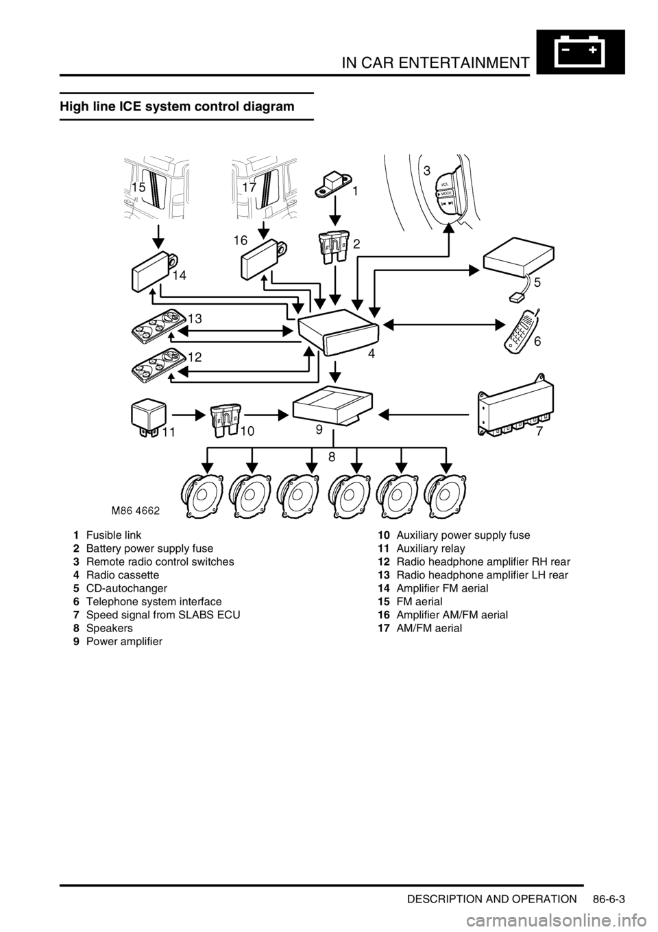
High line ICE system control diagram
1Fusible link
2Battery power supply fuse
3Remote radio control switches
4Radio cassette
5CD-autochanger
6Telephone system interface
7Speed signal from SLABS ECU
8Speakers
9Power amplifier10Auxiliary power supply fuse
11Auxiliary relay
12Radio headphone amplifier RH rear
13Radio headphone amplifier LH rear
14Amplifier FM aerial
15FM aerial
16Amplifier AM/FM aerial
17AM/FM aerial
Page 1557 of 1672

IN CAR ENTERTAINMENT
86-6-4 DESCRIPTION AND OPERATION
Description
General
The in car entertainment (ICE) system allows the driver and passengers to listen to audio output from the speakers
or optional headphones inside the vehicle. Buttons or knobs on the radio cassette allow changes of levels or
selections during the various modes of operation. The system can be controlled from the fascia mounted radio
cassette, or optional remote control switches on the left hand side of the steering wheel. High line systems may also
have rear headphone amplifiers that have some control of the system via the radio cassette player.
One or two amplified aerials located in the rear side windows send radio signals to the radio cassette player. On high
line systems a power amplifier and a CD-autochanger may be located under the front seats. Speakers are located in
the lower door panels, additional speakers may be located in upper door trim, the A-post and the tail door. A display
screen shows the user the current system status.
The ICE supplied varies with trim level and market. Vehicles may not have all of the speakers, amplified aerials, CD-
autochanger, rear headphone amplifiers or power amplifier.
Base system radio cassette
The base radio cassette has buttons for LD (loudness) AM, FM, EJECT (tape), Reverse, Base/Balance, treble, MAN
forward and reverse. The base radio cassette is located in the center of the fascia and contains the radio and tape
player, four clips (accessible through holes in the front of the unit) secure the unit in the fascia. To remove the unit
the four clips must be released with a special tool. The base system can be controlled from the fascia mounted radio
cassette. A logic control circuit in the radio cassette player controls the operation in the various control modes.
The radio cassette has a display screen, the information shown can be the current radio frequency, tape operating,
bass or loudness settings. Power for the illumination on the radio cassette is supplied from the passenger
compartment fuse box. A main fuse is also located in the connector socket area on the back of the radio cassette.
Security code function
A combination of buttons on the radio cassette are used to input and change security codes. Security codes make the
unit unusable if the unit is disconnected from the vehicle without deactivating the security code. The radio cassette
has an internal memory chip that stores the code information, if the power is removed from the unit the chip will
activate the security code feature. For this reason the security code feature must be deactivated before the unit is
removed or the vehicles battery is disconnected.
Audio functions
The radio cassette has buttons for the following audio functions: LD (loudness), bass/balance, fader, treble and
volume.
Cassette functions
The radio cassette has buttons for the following cassette functions: eject, forward, reverse and tape reversal.
Multi function buttons
The function of presets 1-6 and the MAN button depends on current mode of operation and allows selection of radio
band, radio on, tape track and search/seek functions. The MAN button is mode dependent, when pressed the button
allows manual operation or alternate mode selections such as manual tuning.
Internal memory
An internal memory chip stores the station presets and security code, power is supplied internally to the chip via a
permanent power feed, supplied from the passenger compartment fuse box.
Page 1558 of 1672

IN CAR ENTERTAINMENT
DESCRIPTION AND OPERATION 86-6-5
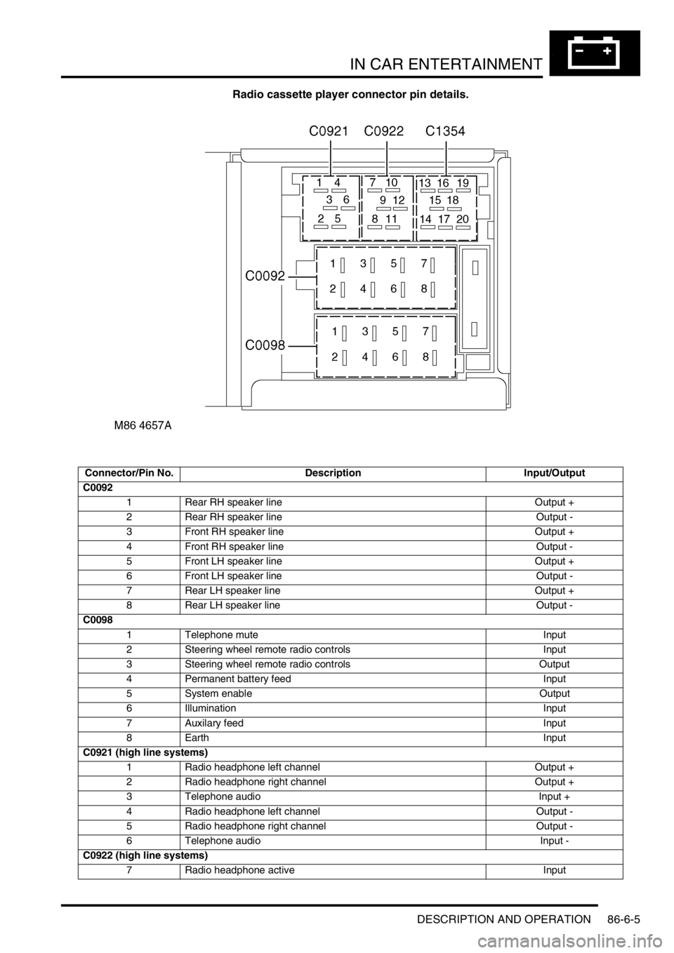
Radio cassette player connector pin details.
Connector/Pin No. Description Input/Output
C0092
1 Rear RH speaker line Output +
2 Rear RH speaker line Output -
3 Front RH speaker line Output +
4 Front RH speaker line Output -
5 Front LH speaker line Output +
6 Front LH speaker line Output -
7 Rear LH speaker line Output +
8 Rear LH speaker line Output -
C0098
1 Telephone mute Input
2 Steering wheel remote radio controls Input
3 Steering wheel remote radio controls Output
4 Permanent battery feed Input
5 System enable Output
6 Illumination Input
7 Auxilary feed Input
8EarthInput
C0921 (high line systems)
1 Radio headphone left channel Output +
2 Radio headphone right channel Output +
3 Telephone audio Input +
4 Radio headphone left channel Output -
5 Radio headphone right channel Output -
6 Telephone audio Input -
C0922 (high line systems)
7 Radio headphone active Input
Page 1559 of 1672

IN CAR ENTERTAINMENT
86-6-6 DESCRIPTION AND OPERATION
Midline system radio cassette
The midline radio cassette is located in the center of the fascia and contains the radio and tape player, four clips
(accessible through holes in the front of the unit) secure the unit. To remove the radio cassette unit the four clips
must be released with a special tool. The midline system can be controlled from the fascia mounted radio cassette,
or from remote radio control switches on the left hand side of the steering wheel. The audio signal can be from the
radio, cassette player or a optional CD-autochanger. A logic control circuit in the radio cassette player controls the
operation in the various control modes.
The radio cassette has a display screen, information shown can include current status, station (radio mode) or
cassette tape track or (optional) CD-autochanger track/disc status. Power for illumination on the radio cassette is
supplied from the passenger compartment fusebox. A main fuse is also located in the connector socket area on the
back of the radio cassette.
Security code function
A combination of buttons on the radio cassette are used to input and change security codes. Security codes make the
unit unusable if the unit is disconnected from the vehicle without deactivating the security code. The radio cassette
has an internal memory chip that stores the information, if the power is removed from the unit the chip will activate the
security code feature. For this reason the security code feature must be deactivated before the unit is removed or the
vehicles battery is disconnected.
Audio functions
A rotary knob allows changes of levels or selections during the various modes of operation, this includes volume,
bass, treble and fader.
Cassette functions
The radio cassette has buttons for the following cassette functions eject, tape, reverse, forward, tape eject/reversal.
Radio functions
The radio cassette has buttons for the selection of AM or FM reception. Selection of the radio station is controlled by
the use of the multi-function buttons on the radio cassette player, the radio headphone amplifiers or the remote radio
controls on the steering wheel.
Traffic information and news function
A traffic information button (TA/NEWS) allows traffic or news information to be selected on the FM waveband only, in
this mode the audio output will mute when traffic or news messages are received. After the traffic or news message
the radio, cassette tape or CD will resume play, the traffic and news information varies with the country of use and
radio band selected.
8 I-BUS communications Input/Output
9 Audio amplifier spatial imaging enable Output
10 Radio headphone LH remote control Input
11 Radio headphone RH remote control Input
12 Headphone remote controls feed Output
C1354 (high line systems)
13 CD-autochanger audio left channel Input +
14 CD-autochanger audio right channel Input +
15 CD-autochanger audio earth Output
16 CD-autochanger audio left channel Input -
17 CD-autochanger audio right channel Input -
18 Not Used
19 CD-autochanger I-BUS communications link Input/Output
20 CD-autochanger permanent feed Output
Page 1560 of 1672

IN CAR ENTERTAINMENT
DESCRIPTION AND OPERATION 86-6-7
Multi function buttons
Rotary controls are located on the front of the radio cassette for adjustment of bass, treble etc, depending on current
mode selected. Operation of presets 1-6 depends on current mode of operation and allows selection of radio band
(Radio mode on) or CD-autochanger disc (in the CD mode). Scan (Mode dependent) manual or automatic selection
of band or track. RND random play, MODE/MUTE (mode dependent) when pressed the button allows manual
operation or alternate mode selections such as manual tuning, compact disk cue/review, tape forward/rewind modes.
Internal memory
An internal memory chip stores the station presets and security code, power is supplied internally to the chip via a
permanent power feed, supplied from the passenger compartment fuse box.
High line system radio cassette
The high line radio cassette is located in the center of the fascia and contains the radio and tape player. Two clips
(accessible through slots in the front of the unit) secure the unit. To remove the radio cassette unit the two clips must
be released with a special tool. The high line system can be controlled from the fascia mounted radio cassette, or from
remote radio control switches on the left hand side of the steering wheel. In vehicles fitted with radio headphone
amplifiers, the rear seat passengers can control their individual audio output using a headphone amplifier control
panel. The audio signal can be from the radio, cassette player or a CD-autochanger. A logic control circuit in the radio
cassette player controls the operation in the various control modes.
The radio cassette has a display screen, information shown includes current status, station (Radio mode) , CD-
autochanger track/disc status or status of headphone amplifier. Power for illumination on the radio cassette is supplied
from the passenger compartment fusebox. A main fuse is also located in the connector socket area on the back of
the radio cassette. When the radio cassette switch is on, power is made available via internal circuits to the radio
headphone amplifiers.
Security code function
A combination of buttons on the radio cassette are used to input and change security codes. Security codes make the
unit unusable if the unit is disconnected from the vehicle without deactivating the security code. The radio cassette
has an internal memory chip that stores the information, if the power is removed from the unit the chip will activate the
security code feature. For this reason the security code feature must be deactivated before the unit is removed or the
vehicles battery is disconnected.
Audio functions
A rotary knob allows changes of levels or selections during the various modes of operation, this includes volume,
bass, treble, fader and spatial on/off.
Cassette functions
The radio cassette has buttons for the following cassette functions; eject, fast forward, rewind and dolby. The dolby
symbol is shown on the dot matrix display screen if dolby mode is selected.
Radio functions
The radio cassette has buttons for the selection of AM or FM reception. Selection of the radio station is controlled by
the use of the multi-function buttons on the radio cassette player, the radio headphone amplifiers or the remote radio
controls on the steering wheel.
CD-autochanger functions
The CD button on the radio cassette player allows selection of the CD-autochanger. CD disc and track selection is
controlled by the use of the multi-function buttons on the radio cassette player, the radio headphone amplifiers or the
remote radio controls on the steering wheel.