ECO mode LAND ROVER DISCOVERY 2002 Service Manual
[x] Cancel search | Manufacturer: LAND ROVER, Model Year: 2002, Model line: DISCOVERY, Model: LAND ROVER DISCOVERY 2002Pages: 1672, PDF Size: 46.1 MB
Page 1026 of 1672

REAR SUSPENSION
DESCRIPTION AND OPERATION 64-21
Normal ride height
When the vehicle is stationary, a door is open and the ignition is off, the SLS system will allow the rear of the vehicle
to lower to within 20 mm of the normal ride height as load is removed from the vehicle. The SLS system will only
operate the compressor to raise the rear of the vehicle when the engine is running, unless requested using the remote
handset.
Off-road mode (ORM)
ORM is used to raise the rear of the vehicle from normal ride height to the ORM ride height of 100 mm between the
tip of the bump stop and the axle.
ORM is activated by depressing the ORM switch located on the fascia for not less than 0.5 seconds. With the engine
running, all doors closed and the vehicle speed below 18 mph (30 km/h), the audible warning will sound once and the
ORM warning lamp in the instrument pack will start to flash when the switch is released. The compressor will be
started and the air control valves will be energised by the ECU to inflate the air springs and raise the rear of the vehicle.
When the full ORM height is reached, the ECU will terminate compressor operation and close the air valves. The ORM
warning lamp will stop flashing and remain continuously illuminated to inform the driver that the SLS system is in ORM.
When ORM is no longer required, depressing the ORM switch for not less than 0.5 seconds with all doors closed will
lower the SLS to normal ride height. The audible warning will sound once and the ORM warning lamp will flash as the
suspension lowers. The ECU energises the air control valves and the exhaust valve to release air pressure from the
air springs. When standard ride height is reached the ORM warning lamp will extinguish and the ECU will de-energise
the air control valves and the exhaust valve solenoids.
If the SLS is in ORM and the vehicle speed exceeds 18 mph (30 km/h), the ECU will lower the SLS to standard ride
height. The driver will be informed of this by an audible warning and the ORM warning lamp flashing as the suspension
lowers. When normal ride height is achieved, the ORM warning lamp will extinguish.
At sea level, the time to change the SLS from normal ride height to ORM or visa versa will take between 15 and 20
seconds.
If the ECU determines that conditions are not correct for SLS operation, i.e.; axle articulation or system fault, the
audible warning will sound three times to inform the driver that the ORM request has not been granted.
Extended mode
The extended mode is automatically operated by the ECU and requires no input from the driver. Extended mode
operates when the chassis is grounded causing the rear wheels to spin. This information is generated by the ABS
function of the SLABS ECU.
When the ECU senses that the chassis is grounded and the vehicle speed is less than 6 mph (10 km/h), the ECU will
operate the compressor and energise the air control valves for 25 seconds to raise the rear of the vehicle. This
operates irrespective of the mode that the SLS system is in at that time. To inform the driver, the ORM warning lamp
will flash continuously at all times that the system is in extended mode.
The driver can exit the extended mode by depressing the ORM switch for not less than 0.5 seconds or by exceeding
8 mph (13 km/h).
Remote handset SLS control
The remote handset is an accessory item which allows the SLS to be operated between normal ride height and bump
stop height to allow easier connection and disconnection of trailers. The remote handset is similar in appearance to
that of the remote door locking handset but does not have an integral key. A circular button with an arrow is used to
raise the SLS and an oval button with the 'Land Rover' logo is used to lower the SLS.
The remote handset control requires all doors to be closed and the ignition to be in position II, but the engine does
not need to be running.
Page 1027 of 1672

REAR SUSPENSION
64-22 DESCRIPTION AND OPERATION
Pressing the lower button will signal the SLABS ECU, via the RF receiver and the BCU, to energise the exhaust valve
and air control valves. The SLS will lower up to 60 mm (2.36 in) below normal ride height if the button is held. If the
button is released the SLS will stop at that point.
Pressing the raise button will signal the SLABS ECU, via the RF receiver and the BCU, to start the compressor and
energise the exhaust valve and air control valves. The SLS will raise to normal ride height if the button is held. If the
button is released the SLS will stop at that point.
When raising or lowering the SLS using the remote handset, the SLS warning lamp will flash and the audible warning
will sound when the system is operating. When the SLS is fully lowered the warning lamp will stay illuminated. The
SLS will reset to normal ride height if the vehicle speed exceeds 3 mph (5 km/h) for 10 seconds when the SLS is
lowered.
Transportation mode
Transportation mode must be used when the vehicle is transported on a trailer and secured by the chassis. The
transportation mode can only be enabled and disabled with TestBook.
The transportation mode lowers the rear suspension onto the bump stops with the engine not running. When the
suspension is in transportation mode, the SLS warning lamp is continuously illuminated when the ignition is in position
II.
When the engine is started in transportation mode, the SLS system will raise the rear suspension until a gap of 25
mm (1 in.) exists between the bump stop and the axle. The SLS warning lamp will flash continuously while the SLS
system is raising the suspension. When the gap between the bump stop and the axle is achieved, the warning lamp
will illuminate continuously.
When TestBook is used to disable the transportation mode, the rear suspension will raise to normal ride height when
the engine is running.
Page 1050 of 1672
BRAKES
DESCRIPTION AND OPERATION 70-5
Description
General
The brakes consist of front and rear disc brakes operated by a diagonally split, dual circuit hydraulic system with
vacuum servo power assistance. The system incorporates the following control functions as standard on all models:
lAnti-lock Brakes (ABS), to prevent road wheels locking during brake application.
lElectronic Brake Distribution (EBD), to control distribution of hydraulic pressure between front and rear axles.
Replaces mechanical pressure limiting valve of previous systems.
lElectronic Traction Control (ETC), to maintain even torque distribution to the road wheels.
lHill Descent Control (HDC), to provide controlled descent ability in off road conditions.
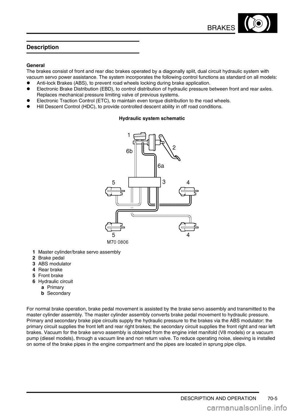
Hydraulic system schematic
1Master cylinder/brake servo assembly
2Brake pedal
3ABS modulator
4Rear brake
5Front brake
6Hydraulic circuit
aPrimary
bSecondary
For normal brake operation, brake pedal movement is assisted by the brake servo assembly and transmitted to the
master cylinder assembly. The master cylinder assembly converts brake pedal movement to hydraulic pressure.
Primary and secondary brake pipe circuits supply the hydraulic pressure to the brakes via the ABS modulator: the
primary circuit supplies the front left and rear right brakes; the secondary circuit supplies the front right and rear left
brakes. Vacuum for the brake servo assembly is obtained from the engine inlet manifold (V8 models) or a vacuum
pump (diesel models), through a vacuum line and non return valve. To reduce operating noise, sleeving is installed
on some of the brake pipes in the engine compartment and the pipes are located in sprung pipe clips.
Page 1059 of 1672

BRAKES
70-14 DESCRIPTION AND OPERATION
The ABS modulator is a 4 channel unit that controls the supply of hydraulic pressure to the brakes in response to
inputs from the SLABS ECU. The modulator is attached by three mounting bushes to a bracket on the LH inner front
wing, and connected to the primary and secondary hydraulic circuits downstream of the master cylinder assembly.
Three electrical connectors link the ABS modulator to the vehicle wiring.
Passages within the ABS modulator, separated into primary and secondary circuits, connect to the various internal
components that control the supply of hydraulic pressure to the brakes:
lShuttle valves and non return valves control the flow through the internal circuits.
lShuttle valve switches, connected in series to the SLABS ECU, provide a brakes on/off signal.
lA damper chamber and restrictor are included in each circuit to refine system operation.
lInlet and outlet solenoid valves control the flow to the individual brakes.
lAn expansion chamber is connected to each circuit to absorb pressure.
lA return pump is connected to both circuits to provide a pressure source.
The ABS modulator has three operating modes: Normal braking, ABS braking and active braking.
Normal braking mode
When the brake pedal is pressed, pressurised fluid from the master cylinder assembly moves the shuttle valves to
open lines 'A' and close the shuttle valve switches. Pressurised fluid then flows through the open inlet solenoid valves
to operate the brakes. The closed shuttle valve switches supply a brakes on signal to the SLABS ECU. If the SLABS
ECU determines that EBD is necessary, it energises the inlet solenoid valves for the brakes of one axle. The inlet
solenoid valves close to isolate the brakes from any further increase in hydraulic pressure.
ABS braking mode
When in the normal braking mode, if the SLABS ECU determines that ABS braking is necessary, it energises the inlet
and outlet solenoid valves of the related brake and starts the return pump. The inlet solenoid valve closes to isolate
the brake from pressurised fluid; the outlet solenoid valve opens to release pressure from the brake into the expansion
chamber and the return pump circuit. The brake releases and the wheel begins to accelerate. The SLABS ECU then
operates the inlet and outlet solenoid valves to control the supply of hydraulic pressure to the brake and apply the
maximum braking effort (for the available traction) without locking the wheel.
Active braking mode
When ETC or HDC are enabled, and the SLABS ECU determines that active braking is necessary, it starts the return
pump. Hydraulic fluid, drawn from the reservoirs through the master cylinder, shuttle valves and lines 'B', is
pressurised by the return pump and supplied to lines 'A'. The SLABS ECU then operates the inlet and outlet solenoid
valves to control the supply of hydraulic pressure to the individual brakes and slow the wheel(s).
Page 1065 of 1672
BRAKES
70-20 DESCRIPTION AND OPERATION
Operation
Refer to illustration.
+ BRAKES, DESCRIPTION AND OPERATION, Brake system control diagram.
When the ignition is switched on, the SLABS ECU performs a check of the brake related warning lamps as part of the
power up procedure. The warning lamps are illuminated for approximately 3 seconds and then extinguished. If a fault
warning lamp remains illuminated after the lamp check, a fault has been detected and repair action is required.
ABS
The ABS function prevents the road wheels locking during brake application, thus maintaining vehicle stability even
under emergency conditions.
WARNING: ABS is an aid to retaining steering control and stability while braking:
lABS cannot defy the natural laws of physics acting on the vehicle.
lABS will not prevent accidents resulting from excessive cornering speeds, following another vehicle too
closely, aquaplaning, etc.
lThe additional control provided by ABS must never be exploited in a dangerous or reckless manner
which could jeopardise the safety of driver or other road users.
lThe fitting of ABS does not imply that the vehicle will always stop in a shorter distance.
NOTE: During normal braking the feel of the brake pedal on vehicles equipped with ABS will be the same as that on
non ABS vehicles. During anti-lock braking operation the driver will experience feedback in the form of a pulsating
brake pedal and solenoid/pump motor noise from the ABS modulator.
The anti-lock braking function is automatically enabled whenever the ABS modulator is in the normal braking mode.
While the anti-lock braking function is enabled, if the SLABS ECU detects a wheel decelerating faster than the
average and at the calibrated wheel slip limit for ABS operation, it operates the ABS modulator in the ABS braking
mode for the affected wheel.
EBD
The EBD function optimises the distribution of hydraulic pressure between the front and rear axles, under all vehicle
load configurations and road conditions, to maintain vehicle stability during braking. EBD operates in forward and
reverse and is automatically enabled whenever the ABS modulator is in the normal braking mode at vehicle
deceleration rates of 0.3 g and above (i.e. medium to high brake pedal loads). EBD operation is similar to that of ABS,
but is calibrated to intervene at lower wheel slip limits and operates the brakes in axle pairs instead of individually.
During braking, if the SLABS ECU detects the wheels of one axle going slower than those of the other axle, i.e. a
potential wheel slip situation, it signals the ABS modulator to close the inlet solenoid valve for the brakes of the slower
wheels. This prevents any further increase in hydraulic pressure to those brakes, while allowing the hydraulic pressure
to the brakes on the other axle to increase and so maximise the overall braking effort. If the wheel speeds of the axle
being subjected to EBD control return within the calibrated wheel slip limits, the SLABS ECU signals a stepped
opening of the inlet solenoid valves, which allows a progressive increase of hydraulic pressure to the related brakes.
Operation of EBD is detectable from a stiffening of brake pedal movement as the inlet solenoid valves close and a
slight pulsing of the brake pedal as the inlet solenoid valves open. EBD operation ceases immediately the brake pedal
is released.
The wheel slip limit for EBD operation varies with vehicle speed. During normal operation, the inlet solenoid valves
always operate in axle pairs, with only one axle pair closed at any one time. Since the most lightly loaded wheel during
a braking manoeuvre will usually be the first to reach the slip limit, under most vehicle load configurations and road
conditions EBD control occurs on the trailing axle. However, EBD control can occur on the leading axle or switch
between axles during the braking manoeuvre.
Page 1066 of 1672

BRAKES
DESCRIPTION AND OPERATION 70-21
ETC
The ETC function uses brake intervention to prevent wheel spin and maintain even torque distribution to the wheels.
ETC is automatically enabled while the brakes are off at speeds up to 62.5 mph (100 km/h), and operates the brakes
either individually or in axle pairs:
lAt speeds up to 31.3 mph (50 km/h), ETC uses individual brake intervention to maintain even torque distribution
between wheels on the same axle.
lVehicles up to 03 model year – At speeds between 0 and 62.5 mph (0 and 100 km/h), ETC also uses brake
intervention in axle pairs to maintain even torque distribution between the front and rear axles. In effect, this mode
of operation replaces the centre differential lock of the transfer box which, although still incorporated, is non
operational under normal driving conditions.
+ TRANSFER BOX - LT230SE, DESCRIPTION AND OPERATION, Description. If the centre differential
lock is in the locked condition, the SLABS ECU illuminates the ABS and ETC warning lamps and inhibits the ETC
function (the ABS, EBD and HDC functions are retained, but at degraded performance levels).
lVehicles from 03 model year (with differential lock fitted) – At speeds between 0 and 62.5 mph (0 and 100
km/h), ETC uses brake intervention in axle pairs to maintain even torque distribution between the front and rear
axles. If the centre differential lock is in the locked condition, the differential lock warning lamp in the instrument
pack is illuminated. The ABS, EBD, ETC and HDC functions are retained, but with revised parameters to suit the
locked differential.
While the ETC function is enabled, if the SLABS ECU detects a wheel accelerating faster than the average, indicating
loss of traction, it operates the ABS modulator in the active braking mode. Depending on the vehicle speed, active
braking is employed for either the brake of the affected wheel or for both brakes on the affected axle, until all four
wheels are driven at approximately the same speed again. During active braking the SLABS ECU also illuminates the
ETC warning lamp, for a minimum of 2 seconds or for the duration that ETC is active. ETC operation is desensitised
during 'hard' cornering.
HDC
HDC uses brake intervention to provide a controlled descent ability in off road conditions when engine braking is
insufficient to maintain a comfortable speed. This allows the driver to leave HDC selected and to control the vehicle's
descent speed, down to the system's minimum target speed, using only the accelerator pedal. The HDC function is
selected on/off by a switch on the fascia. When selected on, HDC is enabled in all forward gears and reverse provided:
lVehicle speed is below 31.3 mph (50 km/h).
lThe transfer box is in low range.
lOn manual gearbox vehicles, the clutch is engaged.
When HDC is enabled, the HDC information warning lamp illuminates. If HDC is selected outside the above
conditions, the HDC information warning lamp flashes and the audible warning sounds continuously.
When HDC is enabled, the SLABS ECU calculates a target speed from the throttle position element of the engine data
input, and compares this with actual speed. If the actual speed is higher than the target speed, the SLABS ECU
operates the ABS modulator in the active braking mode to slow the vehicle down to the target speed. While the braking
force is being applied, the SLABS ECU also energizes the brake lamp relay to put the brake lamps on. Active braking
is discontinued while vehicle speed is below the target speed or if the foot brakes are applied. Applying the foot brakes
during active braking may result in a pulse through the brake pedal, which is normal.
During active braking, the brakes are operated predominantly on the wheels of the leading axle, but if that is not
sufficient to achieve the required deceleration the brakes of the trailing axle are also applied. The deceleration rate is
dependent on the speed differential between initial vehicle speed and the target speed. The deceleration rates are
relatively low at higher speed differentials, then progressively increase as vehicle speed approaches the target speed.
Anti-lock braking is also enabled during active braking, but at very low speeds some wheel lock can occur.
The target speed increases as the accelerator pedal is pressed, from a programmed minimum with the accelerator
pedal released, up to a maximum of 31.3 mph (50 km/h). For any given accelerator pedal position, while travelling
uphill or on level ground the target speed is always greater than the corresponding vehicle speed, which allows the
vehicle to be driven normally without HDC intervention. However, when travelling downhill, the gravitational effect on
the vehicle means that for any given accelerator pedal position the target speed is less than the corresponding vehicle
speed, and HDC intervenes to limit vehicle speed to the target speed.
Page 1069 of 1672

BRAKES
70-24 DESCRIPTION AND OPERATION
Default strategies
Electrical data
Nominal resistance values for applicable brake control components are as detailed below:
Fault Default strategy
Brake lamps relay ABS: Enabled.
ETC: Enabled.
EBD: Enabled.
HDC: Enabled.
Throttle position signal failure ABS: Enabled.
ETC: Disabled.
EBD: Enabled.
HDC: Immediately disabled if not in active braking mode; faded out then disabled if in active
braking mode.
No reference earth ABS: Disabled.
ETC: Disabled.
EBD: Partly disabled.
HDC: Disabled.
Return pump or relay fault ABS: Disabled.
ETC: Disabled.
EBD: Partly disabled.
HDC: Disabled.
Shuttle valve switch failure ABS: Deceleration threshold increased; return pump activated if sum of output valve
actuation on one axle exceeds 140 milliseconds.
ETC: Disabled.
EBD: Inlet valves of rear axle close at vehicle deceleration rates of 0.3 g and above.
HDC: Disabled.
SLABS ECU internal failure ABS: Disabled.
ETC: Disabled.
EBD: Disabled.
HDC: Disabled.
Supply voltage out of limits ABS: Disabled.
ETC: Disabled.
EBD: Disabled.
HDC: Disabled.
Component Resistance, ohms
Brake lamp relay coil117 - 143
Return pump relay coil82.8 - 101.2
ABS sensor950 - 1100
Shuttle valve switches, both open (brakes off) 2977 - 3067
Shuttle valve switches, both closed (brakes on) 1007 - 1037
Shuttle valve switches, one open, one closed 1992 - 2052
Inlet solenoid valve5.9 - 7.3
Outlet solenoid valve3.0 - 3.6
Page 1115 of 1672
RESTRAINT SYSTEMS
75-20 REPAIRS
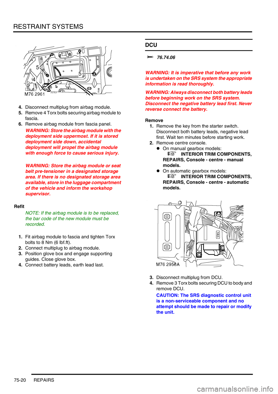
4.Disconnect multiplug from airbag module.
5.Remove 4 Torx bolts securing airbag module to
fascia.
6.Remove airbag module from fascia panel.
WARNING: Store the airbag module with the
deployment side uppermost. If it is stored
deployment side down, accidental
deployment will propel the airbag module
with enough force to cause serious injury.
WARNING: Store the airbag module or seat
belt pre-tensioner in a designated storage
area. If there is no designated storage area
available, store in the luggage compartment
of the vehicle and inform the workshop
supervisor.
Refit
NOTE: If the airbag module is to be replaced,
the bar code of the new module must be
recorded.
1.Fit airbag module to fascia and tighten Torx
bolts to 8 Nm (6 lbf.ft).
2.Connect multiplug to airbag module.
3.Position glove box and engage supporting
guides. Close glove box.
4.Connect battery leads, earth lead last.
DCU
$% 76.74.06
WARNING: It is imperative that before any work
is undertaken on the SRS system the appropriate
information is read thoroughly.
WARNING: Always disconnect both battery leads
before beginning work on the SRS system.
Disconnect the negative battery lead first. Never
reverse connect the battery.
Remove
1.Remove the key from the starter switch.
Disconnect both battery leads, negative lead
first. Wait ten minutes before starting work.
2.Remove centre console.
lOn manual gearbox models:
+ INTERIOR TRIM COMPONENTS,
REPAIRS, Console - centre - manual
models.
lOn automatic gearbox models:
+ INTERIOR TRIM COMPONENTS,
REPAIRS, Console - centre - automatic
models.
3.Disconnect multiplug from DCU.
4.Remove 3 Torx bolts securing DCU to body and
remove DCU.
CAUTION: The SRS diagnostic control unit
is a non-serviceable component and no
attempt should be made to repair or modify
the unit.
Page 1173 of 1672
INTERIOR TRIM COMPONENTS
76-3-20 REPAIRS
Headlining
$% 76.64.15.21
Remove
1.Remove both 'D' post trim casings.
+ INTERIOR TRIM COMPONENTS,
REPAIRS, Trim casing - 'D' post.
2.Remove both 'B' post upper trim casings.
+ INTERIOR TRIM COMPONENTS,
REPAIRS, Trim casing - upper - 'B' post.
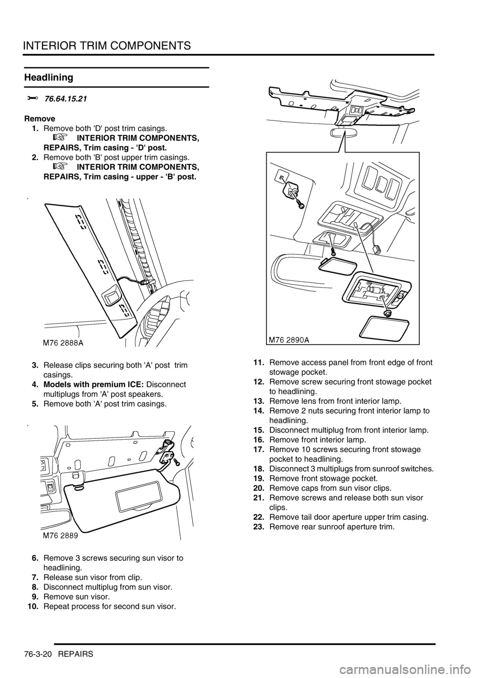
3.Release clips securing both 'A' post trim
casings.
4. Models with premium ICE: Disconnect
multiplugs from 'A' post speakers.
5.Remove both 'A' post trim casings.
6.Remove 3 screws securing sun visor to
headlining.
7.Release sun visor from clip.
8.Disconnect multiplug from sun visor.
9.Remove sun visor.
10.Repeat process for second sun visor. 11.Remove access panel from front edge of front
stowage pocket.
12.Remove screw securing front stowage pocket
to headlining.
13.Remove lens from front interior lamp.
14.Remove 2 nuts securing front interior lamp to
headlining.
15.Disconnect multiplug from front interior lamp.
16.Remove front interior lamp.
17.Remove 10 screws securing front stowage
pocket to headlining.
18.Disconnect 3 multiplugs from sunroof switches.
19.Remove front stowage pocket.
20.Remove caps from sun visor clips.
21.Remove screws and release both sun visor
clips.
22.Remove tail door aperture upper trim casing.
23.Remove rear sunroof aperture trim.
Page 1175 of 1672
INTERIOR TRIM COMPONENTS
76-3-22 REPAIRS
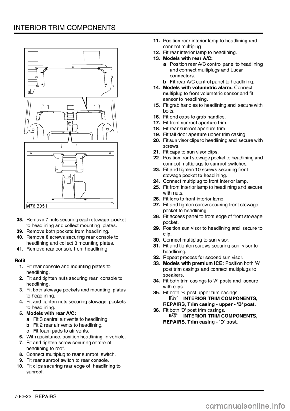
38.Remove 7 nuts securing each stowage pocket
to headlining and collect mounting plates.
39.Remove both pockets from headlining.
40.Remove 8 screws securing rear console to
headlining and collect 3 mounting plates.
41.Remove rear console from headlining.
Refit
1.Fit rear console and mounting plates to
headlining.
2.Fit and tighten nuts securing rear console to
headlining.
3.Fit both stowage pockets and mounting plates
to headlining.
4.Fit and tighten nuts securing stowage pockets
to headlining.
5. Models with rear A/C:
aFit 3 central air vents to headlining.
bFit 2 rear air vents to headlining.
cFit foam pads to air vents.
6.With assistance, position headlining in vehicle.
7.Fit and tighten screw securing centre of
headlining to roof.
8.Connect multiplug to rear sunroof switch.
9.Fit rear sunroof switch to rear console.
10.Fit clips securing rear edge of headlining to
sunroof. 11.Position rear interior lamp to headlining and
connect multiplug.
12.Fit rear interior lamp to headlining.
13. Models with rear A/C:
aPosition rear A/C control panel to headlining
and connect multiplugs and Lucar
connectors.
bFit rear A/C control panel to headlining.
14. Models with volumetric alarm: Connect
multiplug to front volumetric sensor and fit
sensor to headlining.
15.Fit grab handles to headlining and secure with
bolts.
16.Fit end caps to grab handles.
17.Fit front sunroof aperture trim.
18.Fit rear sunroof aperture trim.
19.Fit tail door aperture upper trim casing.
20.Fit sun visor clips to headlining and secure with
screws.
21.Fit caps to sun visor clips.
22.Position front stowage pocket to headlining and
connect multiplugs to sunroof switches.
23.Fit and tighten 10 screws securing front
stowage pocket to headlining.
24.Connect multiplug to front interior lamp.
25.Fit front interior lamp to headlining and secure
with nuts.
26.Fit lens to front interior lamp.
27.Fit and tighten screw securing front stowage
pocket to headlining.
28.Fit access panel to front edge of front stowage
pocket.
29.Position sun visor to headlining and secure to
clip.
30.Connect multiplug to sun visor.
31.Fit and tighten screws securing sun visor to
headlining.
32.Repeat process for second sun visor.
33. Models with premium ICE: Position both 'A'
post trim casings and connect multiplugs to
speakers.
34.Fit both trim casings to 'A' posts and secure
with clips.
35.Fit both 'B' post upper trim casings.
+ INTERIOR TRIM COMPONENTS,
REPAIRS, Trim casing - upper - 'B' post.
36.Fit both 'D' post trim casings.
+ INTERIOR TRIM COMPONENTS,
REPAIRS, Trim casing - 'D' post.