ECU LAND ROVER DISCOVERY 2002 Workshop Manual
[x] Cancel search | Manufacturer: LAND ROVER, Model Year: 2002, Model line: DISCOVERY, Model: LAND ROVER DISCOVERY 2002Pages: 1672, PDF Size: 46.1 MB
Page 1355 of 1672

HEATING AND VENTILATION
80-14DESCRIPTION AND OPERATION
Coolant temperature control
When the ECU first enters the active mode, it initiates a start to full load combustion. Full load combustion continues
until the heat exchanger casing temperature reaches 60
°C (140 °F), when the ECU decreases the speed of the FBH
fuel pump and the combustion air fan to half speed, to produce part load combustion. The ECU maintains part load
combustion while the heat exchanger casing temperature remains between 54 and 65
°C (129 and 149 °F). If the heat
exchanger casing temperature decreases to 54
°C (129 °F), the ECU switches the system to full load combustion
again. If the heat exchanger casing temperature increases to 65
°C (149 °F), the ECU enters a control idle phase of
operation.
On entering the control idle phase, the ECU immediately switches the FBH fuel pump off, to stop combustion, and
starts a timer for the combustion air fan. After a 2 minute cooldown period, the ECU switches the combustion air fan
off and then remains in the control idle phase while the heat exchanger casing temperature remains above 59
°C (138
°F). If the heat exchanger casing temperature decreases to 59 °C (138 °F), within 15 minutes of the ECU entering the
control idle phase, the ECU initiates a start to part load combustion. If more than 15 minutes elapse before the heat
exchanger casing temperature decreases to 59
°C (138 °F), the ECU initiates a start to full load combustion.
In order to limit the build-up of carbon deposits on the glow plug/flame sensor, the ECU also enters the control idle
phase if the continuous part and/or full load combustion time exceeds 72 minutes. After the cooldown period, if the
heat exchanger casing is still in the temperature range that requires additional heat, the ECU initiates an immediate
restart to part or full load combustion, as appropriate.
Shutdown
The FBH system is de-activated when the alternator power supply to the FBH unit is disconnected, either by the
engine stopping or, if the ambient temperature increases to 5
°C (41 °F) or above, by the contacts in the air
temperature sensor opening. If the system is active when the alternator power supply is disconnected, the ECU de-
energises the FBH fuel pump to stop combustion, but continues operation of the combustion air fan and the circulation
pump to cool down the FBH unit. The cool down time depends on the combustion load at the time the alternator power
input is disconnected.
Cool down times
Diagnostics
The ECU in the FBH unit monitors the system for faults. Any faults detected are stored in a volatile memory in the the
ECU, which can be interrogated by Testbook. A maximum of three faults and associated freeze frame data can be
stored at any one time. If a further fault is detected, the oldest fault is overwritten by the new fault.
The ECU also incorporates an error lockout mode of operation that inhibits system operation to prevent serious faults
from causing further damage to the system. In the error lockout mode, the ECU immediately stops the FBH fuel pump,
and stops the combustion air fan and circulation pump after a cool down time of approximately 2 minutes. Error lockout
occurs for start sequence failures and/or combustion flameouts, heat exchanger casing overheat and out of limit input
voltage. The error lockout mode can be cleared using Testbook, or by disconnecting the battery power supply for a
minimum of 10 seconds.
Start failure/flameout. If a start sequence fails to establish combustion, or a flameout occurs after combustion is
established, the ECU immediately initiates another start sequence. The start failure or flameout is also recorded by
an event timer in the ECU. The event timer is increased by one after each start failure or flameout, and decreased by
one if a subsequent start is successful. If the event timer increases to three (over any number of drive cycles), the
ECU enters the error lockout mode.
Heat exchanger casing overheat. To protect the system from excessive temperatures, the ECU enters the error
lockout mode if the heat exchanger casing temperature exceeds 105
°C (221 °F).
Out of limit voltage. The ECU enters the error lockout mode if the battery or alternator power input is less than 10.5
±
0.3 V for more than 20 seconds, or more than 15.5
± 0.5 V for more than 6 seconds.
Combustion load Cool down time, seconds
Part 100
Full 175
Page 1356 of 1672

HEATING AND VENTILATION
REPAIRS 80-15
REPAIRS
Heater control and fan switch
$% 80.10.02
Remove
1.Remove louvre panel assembly.
+ INTERIOR TRIM COMPONENTS,
REPAIRS, Louvre panel assembly - centre
fascia.
2.Release temperature and air distribution cable
abutments from heater control housing and
disconnect inner cables from controls.
3.Disconnect multiplugs from switches.
4.Disconnect multiplug from control illumination.
5.Remove heater control.
6.Remove 3 switches from heater control.
Refit
1.Fit switches to heater control housing.
2.Position heater control assembly and connect
multiplugs to switches and illumination.
3.Connect heater control cables and secure
outer cable abutments to casing.
4.Fit louvre panel assembly.
+ INTERIOR TRIM COMPONENTS,
REPAIRS, Louvre panel assembly - centre
fascia.
Cables - heater control
$% 80.10.06
Remove
1. Driver temperature control and air flow
control cables:Release fixings and lower
fascia fuse box access cover.
2. Passenger temperature control cable:
Remove 4 screws securing glove box, release
catch and remove glove box.
Page 1357 of 1672

HEATING AND VENTILATION
80-16REPAIRS
3.Remove louvre panel assembly.
+ INTERIOR TRIM COMPONENTS,
REPAIRS, Louvre panel assembly - centre
fascia.
4.Release control cable abutment from control
housing and disconnect inner cable from
control.
5.Release clip securing control outer cable to
heater case and disconnect inner cable from
flap lever.
6.Remove control cable. Refit
1.Fit new control cable, connect inner cable to
control and secure abutment to control
housing.
2.Fit other end of inner cable to flap lever.
3.Position control to maximum heat for
temperature control cables or demist for air
flow control cable, hold flap lever in fully closed
position and secure outer cable in clip on
heater casing.
4.Refit louvre panel assembly.
+ INTERIOR TRIM COMPONENTS,
REPAIRS, Louvre panel assembly - centre
fascia.
5. Driver temperature and air flow control
cables: Close fuse access cover and secure
fixings.
6. Passenger temperature control cable: Refit
glove box and secure with bolts.
Page 1358 of 1672

HEATING AND VENTILATION
REPAIRS 80-17
Servo - recirculation flap
$% 80.10.18
Remove
1.Remove 4 studs securing passenger toe board
and remove toe board.
2.Remove 4 screws securing glove box, release
catch and remove glove box. 3.Remove bolt securing BCM, release BCM from
retaining peg and lower BCM.
4.Remove 2 nuts securing ECU assembly and
lower ECU assembly to gain access to servo
screws.
5.Disconnect multiplug from servo.
6.Remove 2 screws securing servo.
7.Release servo, disconnect operating lever and
remove servo.
Page 1359 of 1672

HEATING AND VENTILATION
80-18REPAIRS
Refit
1.Position servo and connect operating lever.
2.Fit and tighten screws securing servo.
3.Connect multiplug to servo.
4.Position ECU assembly, fit and tighten nuts.
5.Position BCM, fit and tighten bolt.
6.Position toe board and secure with studs.
7.Position glove box, fit and tighten screws.
Switch - recirculation control
$% 80.10.21
Remove
1.Remove louvre panel assembly.
+ INTERIOR TRIM COMPONENTS,
REPAIRS, Louvre panel assembly - centre
fascia.
2.Disconnect multiplug from recirculation switch.
3.Remove recirculation switch from heater
control panel.
Refit
1.Fit recirculation switch to heater control panel
and connect multiplug.
2.Fit louvre panel assembly.
+ INTERIOR TRIM COMPONENTS,
REPAIRS, Louvre panel assembly - centre
fascia.
Page 1360 of 1672

HEATING AND VENTILATION
REPAIRS 80-19
Servo - air distribution control
$% 80.10.30
Remove
1.Disconnect battery earth lead.
2. RHD models: Remove heater assembly.
+ HEATING AND VENTILATION,
REPAIRS, Heater assembly - models with
air conditioning.
3. LHD models: Remove heater motor assembly.
+ HEATING AND VENTILATION,
REPAIRS, Blower assembly.
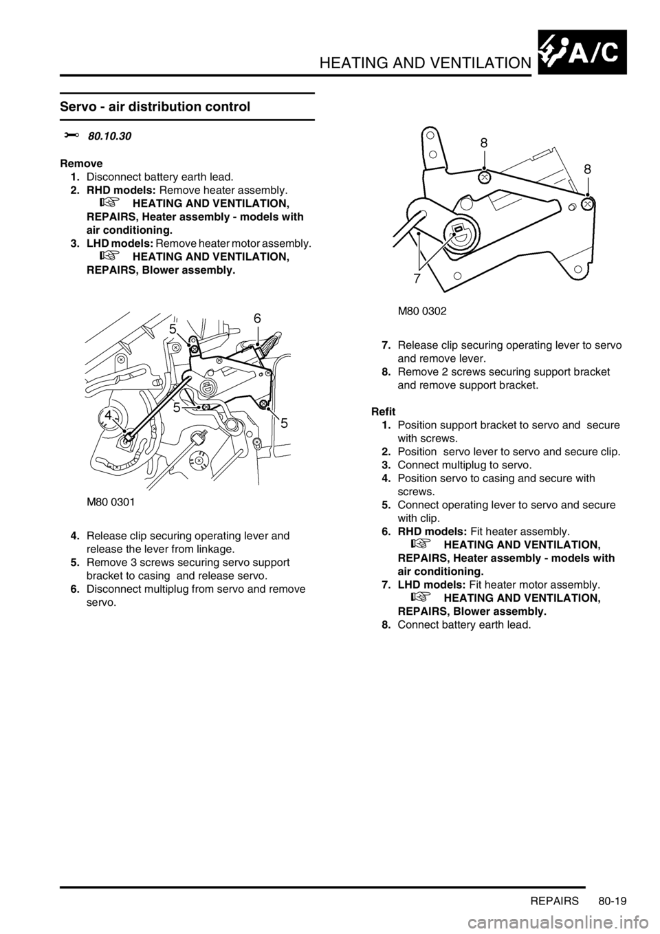
4.Release clip securing operating lever and
release the lever from linkage.
5.Remove 3 screws securing servo support
bracket to casing and release servo.
6.Disconnect multiplug from servo and remove
servo. 7.Release clip securing operating lever to servo
and remove lever.
8.Remove 2 screws securing support bracket
and remove support bracket.
Refit
1.Position support bracket to servo and secure
with screws.
2.Position servo lever to servo and secure clip.
3.Connect multiplug to servo.
4.Position servo to casing and secure with
screws.
5.Connect operating lever to servo and secure
with clip.
6. RHD models: Fit heater assembly.
+ HEATING AND VENTILATION,
REPAIRS, Heater assembly - models with
air conditioning.
7. LHD models: Fit heater motor assembly.
+ HEATING AND VENTILATION,
REPAIRS, Blower assembly.
8.Connect battery earth lead.
Page 1361 of 1672

HEATING AND VENTILATION
80-20REPAIRS
Servo - air temperature control
$% 80.10.42
Remove
1.Disconnect battery earth lead.
2. Driver side: Remove heater assembly.
+ HEATING AND VENTILATION,
REPAIRS, Heater assembly - models with
air conditioning.
3. Passenger side: Remove blower assembly.
+ HEATING AND VENTILATION,
REPAIRS, Blower assembly.
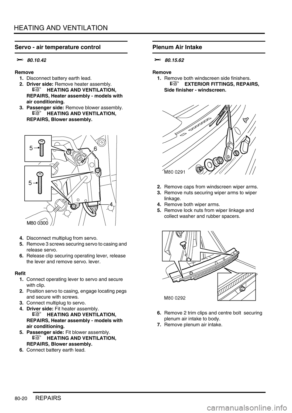
4.Disconnect multiplug from servo.
5.Remove 3 screws securing servo to casing and
release servo.
6.Release clip securing operating lever, release
the lever and remove servo. lever.
Refit
1.Connect operating lever to servo and secure
with clip.
2.Position servo to casing, engage locating pegs
and secure with screws.
3.Connect multiplug to servo.
4. Driver side: Fit heater assembly.
+ HEATING AND VENTILATION,
REPAIRS, Heater assembly - models with
air conditioning.
5. Passenger side: Fit blower assembly.
+ HEATING AND VENTILATION,
REPAIRS, Blower assembly.
6.Connect battery earth lead.
Plenum Air Intake
$% 80.15.62
Remove
1.Remove both windscreen side finishers.
+ EXTERIOR FITTINGS, REPAIRS,
Side finisher - windscreen.
2.Remove caps from windscreen wiper arms.
3.Remove nuts securing wiper arms to wiper
linkage.
4.Remove both wiper arms.
5.Remove lock nuts from wiper linkage and
collect washer and rubber spacers.
6.Remove 2 trim clips and centre bolt securing
plenum air intake to body.
7.Remove plenum air intake.
Page 1362 of 1672

HEATING AND VENTILATION
REPAIRS 80-21
Refit
1.Fit plenum air intake.
2.Fit trim clips and centre bolt securing plenum
air intake to body.
3.Fit rubber spacers and washers to wiper
linkage.
4.Fit locknuts to wiper linkage and tighten to 7
Nm (5.2 lbf.ft).
5.Fit wiper arms to wiper linkage.
6.Fit nuts securing wiper arms to wiper linkage
and tighten to 15 Nm (11 lbf.ft).
7.Fit caps to wiper arms.
8.Fit both windscreen side finishers.
+ EXTERIOR FITTINGS, REPAIRS,
Side finisher - windscreen.
Heater assembly - models without air
conditioning
$% 80.20.01.99
Remove
1.Drain cooling system.
l
+ COOLING SYSTEM - Td5,
ADJUSTMENTS, Drain and refill.
l
+ COOLING SYSTEM - V8,
ADJUSTMENTS, Drain and refill.
2. Diesel models: Remove 3 bolts and remove
engine cover.
3.Release clips and disconnect coolant hoses
from heater pipes.
CAUTION: Always fit plugs to open
connections to prevent contamination.
4.Remove facia assembly.
+ INTERIOR TRIM COMPONENTS,
REPAIRS, Fascia.
Page 1363 of 1672

HEATING AND VENTILATION
80-22REPAIRS
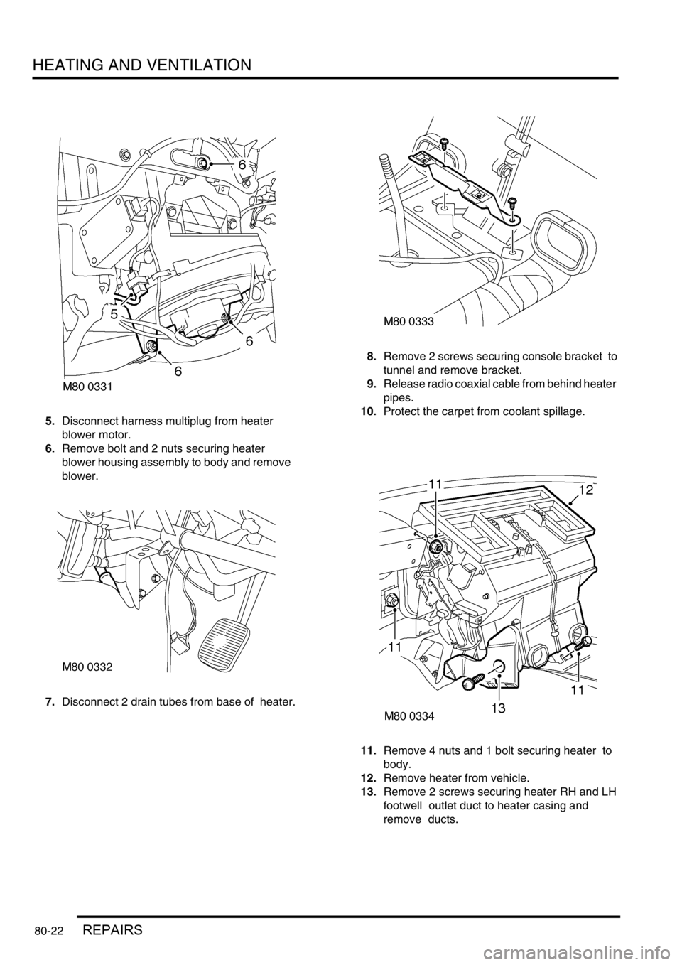
5.Disconnect harness multiplug from heater
blower motor.
6.Remove bolt and 2 nuts securing heater
blower housing assembly to body and remove
blower.
7.Disconnect 2 drain tubes from base of heater. 8.Remove 2 screws securing console bracket to
tunnel and remove bracket.
9.Release radio coaxial cable from behind heater
pipes.
10.Protect the carpet from coolant spillage.
11.Remove 4 nuts and 1 bolt securing heater to
body.
12.Remove heater from vehicle.
13.Remove 2 screws securing heater RH and LH
footwell outlet duct to heater casing and
remove ducts.
Page 1364 of 1672

HEATING AND VENTILATION
REPAIRS 80-23
14.Remove 2 screws securing matrix pipe bracket
to heater casing.
15.Remove screw securing pipe clamp to heater
casing and remove clamp.
16.Carefully remove matrix from heater.
Refit
1.Fit matrix into heater casing.
2.Fit screws securing pipe bracket to heater
casing.
3.Fit pipe clamp and secure with screw.
4.Fit heater ducts and secure with screws.
5.Position heater assembly to vehicle, ensure
heater coolant pipe grommet is correctly
located in bulkhead and secure with nuts and
bolt.
6.Fit radio coaxial cable behind heater pipes.
7.Fit console bracket and secure with screws.
8.Connect drain tubes to base of heater.
9.Fit blower unit to heater and secure to body
with nuts and bolt.
10.Connect harness multiplug to blower motor.
11.Fit facia assembly
+ INTERIOR TRIM COMPONENTS,
REPAIRS, Fascia.
12.Connect heater hoses and secure with clips.
13. Diesel models: Fit engine cover and secure
with bolts.
14.Refill cooling system
l
+ COOLING SYSTEM - Td5,
ADJUSTMENTS, Drain and refill.
l
+ COOLING SYSTEM - V8,
ADJUSTMENTS, Drain and refill.
Heater assembly - models with air
conditioning
$% 80.20.01.98
Remove
1.Drain cooling system.
l
+ COOLING SYSTEM - V8,
ADJUSTMENTS, Drain and refill.
l
+ COOLING SYSTEM - Td5,
ADJUSTMENTS, Drain and refill.
2.Evacuate air conditioning system.
+ AIR CONDITIONING, REFRIGERANT
RECOVERY, RECYCLING AND
RECHARGING, Refrigerant recovery,
recycling and recharging.
3.Release 2 clips securing heater hoses to
heater and release hoses.
4.Remove 2 bolts securing air conditioning pipes
to evaporator, release pipes and discard 'O'
rings.
CAUTION: Always fit plugs to open
connections to prevent contamination.
5.Remove fascia.
+ INTERIOR TRIM COMPONENTS,
REPAIRS, Fascia.