charging LAND ROVER DISCOVERY 2002 Workshop Manual
[x] Cancel search | Manufacturer: LAND ROVER, Model Year: 2002, Model line: DISCOVERY, Model: LAND ROVER DISCOVERY 2002Pages: 1672, PDF Size: 46.1 MB
Page 24 of 1672

CONTENTS
CONTENTS 21
PAINTING ................................................................................................ 77-5-1
PROCEDURES
Panel preparation............................................................................................................................ 77-5-1
Paint preparation............................................................................................................................. 77-5-2
HEATING AND VENTILATION................................................................. 80-1
DESCRIPTION AND OPERATION
Heating and ventilation component layout ...................................................................................... 80-1
Fuel burning heater component layout ........................................................................................... 80-2
Description ...................................................................................................................................... 80-3
Operation ........................................................................................................................................ 80-13
REPAIRS
Heater control and fan switch ....................................................................................................... 80-15
Cables - heater control .................................................................................................................. 80-15
Servo - recirculation flap ............................................................................................................... 80-17
Switch - recirculation control ......................................................................................................... 80-18
Servo - air distribution control ........................................................................................................ 80-19
Servo - air temperature control ....................................................................................................... 80-20
Plenum Air Intake ........................................................................................................................... 80-20
Heater assembly - models without air conditioning ......................................................................... 80-21
Heater assembly - models with air conditioning .............................................................................. 80-23
Blower assembly ............................................................................................................................ 80-25
Motor - blower ............................................................................................................................. 80-26
Resistor pack - power resistor A/C ............................................................................................... 80-27
Heater matrix ................................................................................................................................ 80-28
Pipe - Heater - Feed ...................................................................................................................... 80-29
Pipe - Heater - Return .................................................................................................................... 80-29
Fuel burning heater - (FBH) - Td5................................................................................................... 80-30
AIR CONDITIONING ................................................................................. 82-1
DESCRIPTION AND OPERATION
A/C refrigerant system component layout ....................................................................................... 82-1
A/C control system component layout ............................................................................................ 82-2
Description ...................................................................................................................................... 82-3
Operation ........................................................................................................................................ 82-18
DESCRIPTION AND OPERATION
Rear A/C refrigerant system component layout .............................................................................. 82-23
Rear A/C distribution and control component layout ....................................................................... 82-24
Description ...................................................................................................................................... 82-25
Operation ........................................................................................................................................ 82-27
REFRIGERANT RECOVERY, RECYCLING AND RECHARGING
Refrigerant recovery, recycling and recharging .............................................................................. 82-29
REPAIRS
Compressor - diesel ........................................................................................................................ 82-31
Compressor - V8 ............................................................................................................................. 82-32
Fan - condenser ............................................................................................................................ 82-33
Page 25 of 1672

CONTENTS
22 CONTENTS
Condenser .................................................................................................................................... 82-33
Receiver drier and dual pressure switch......................................................................................... 82-36
ECU - air temperature control ......................................................................................................... 82-37
Sensor - ambient air temperature ................................................................................................ 82-38
Sensor - solar light ........................................................................................................................ 82-38
Sensor - air temperature ............................................................................................................. 82-39
Evaporator, evaporator thermistor and thermal expansion valve (TXV) ........................................ 82-40
Expansion valve - (TXV) - rear ....................................................................................................... 82-42
Evaporator - rear............................................................................................................................. 82-43
Evaporator and motor assembly - rear ........................................................................................... 82-44
Blower motor assembly - rear ......................................................................................................... 82-46
Resistor - blower motor ................................................................................................................. 82-46
Duct - centre - rear.......................................................................................................................... 82-47
WIPERS AND WASHERS ........................................................................ 84-1
DESCRIPTION AND OPERATION
Wipers and washers component layout .......................................................................................... 84-1
Front wiper components ................................................................................................................. 84-2
Rear wiper components .................................................................................................................. 84-3
Washer components ....................................................................................................................... 84-4
Wipers and washers block diagram ................................................................................................ 84-6
Description ...................................................................................................................................... 84-8
Operation ........................................................................................................................................ 84-16
REPAIRS
Reservoir - washer - up to 03MY .................................................................................................... 84-19
Reservoir - washer - from 03MY ..................................................................................................... 84-20
Jet - washer - windscreen ............................................................................................................... 84-21
Pump - washer - screen and headlamp ....................................................................................... 84-21
Motor and linkage - wiper - windscreen .......................................................................................... 84-22
Switch - wiper and washer - windscreen ........................................................................................ 84-23
Jet - washer - headlamp ................................................................................................................ 84-24
Jet - washer - rear screen ............................................................................................................ 84-25
Switch - rear wash .......................................................................................................................... 84-25
Motor - wiper - rear screen ............................................................................................................ 84-26
Switch - wiper - rear - up to 03MY .................................................................................................. 84-27
Switch - wiper - rear - from 03MY ................................................................................................... 84-27
CHARGING AND STARTING ................................................................... 86-1-1
REPAIRS
Alternator - diesel .......................................................................................................................... 86-1-1
Alternator - V8................................................................................................................................. 86-1-2
Belt - auxiliary drive ........................................................................................................................ 86-1-3
Battery ........................................................................................................................................... 86-1-4
Battery carrier ................................................................................................................................ 86-1-4
Starter motor - diesel ...................................................................................................................... 86-1-5
Starter motor - V8 ........................................................................................................................... 86-1-6
LIGHTING.................................................................................................. 86-2-1
ADJUSTMENTS
Headlamps beam alignment - up to 03MY ..................................................................................... 86-2-1
Page 38 of 1672

GENERAL INFORMATION
03-3
Environmental Precautions
General
This section provides general information which can
help to reduce the environmental impacts from the
activities carried out in workshops.
Emissions to air
Many of the activities that are carried out in
workshops emit gases and fumes which contribute to
global warming, depletion of the ozone layer and/or
the formation of photochemical smog at ground
level. By considering how the workshop activities are
carried out, these gases and fumes can be
minimised, thus reducing the impact on the
environment.
Exhaust fumes
Running car engines is an essential part of workshop
activities and exhaust fumes need to be ventilated to
atmosphere. However, the amount of time engines
are running and the position of the vehicle should be
carefully considered at all times, to reduce the
release of poisonous gases and minimise the
inconvenience to people living nearby.
Solvents
Some of the cleaning agents used are solvent based
and will evaporate to atmosphere if used carelessly,
or if cans are left unsealed. All solvent containers
should be firmly closed when not needed and
solvent should be used sparingly. Suitable
alternative materials may be available to replace
some of the commonly used solvents. Similarly,
many paints are solvent based and the spray should
be minimised to reduce solvent emissions.
Refrigerant
It is illegal to release any refrigerants into the
atmosphere. Discharge and replacement of these
materials from air conditioning units should only be
carried out using the correct equipment.
Checklist
Always adhere to the following.
Engines:
ldon't leave engines running unnecessarily;
lminimise testing times and check where the
exhaust fumes are being blown.
Materials:
lkeep lids on containers of solvents;
lonly use the minimum quantity;
lconsider alternative materials;
lminimise over-spray when painting. Gases:
luse the correct equipment for collecting
refrigerants;
ldon't burn rubbish on site.
Discharges to water
Most sites will have two systems for discharging
water: storm drains and foul drains. Storm drains
should only receive clean water, foul drains will take
dirty water.
The foul drain will accept many of the normal waste
waters such as washing water, detergents and
domestic type wastes, but oil, petrol, solvent, acids,
hydraulic oil, antifreeze and other such substances
should never be poured down the drain. If in any
doubt speak to the Water Company first.
Every precaution must be taken to prevent spillage of
oil, fuel, solvents etc. reaching the drains. All
handling of such materials must take place well away
from the drains and preferably in an area with a kerb
or wall around it, to prevent discharge into the drain.
If a spillage occurs it should be soaked up
immediately. Having a spill kit available will make
this easier.
Additional precautions
Check whether the surface water drains are
connected to an oil water separator, this could
reduce the pollution if an incident was to occur. Oil
water separators do need regular maintenance to
ensure effectiveness.
Checklist
Always adhere to the following.
Disposal:
lnever pour anything down a drain without first
checking that it is environmentally safe to do so,
and that it does not contravene any local
regulations or bye-laws;
l have oil traps emptied regularly.
Spillage prevention:
lstore liquids in a walled area;
lmake sure that taps on liquid containers are
secure and cannot be accidentally turned on;
lprotect bulk storage tanks from vandalism by
locking the valves;
ltransfer liquids from one container to another in
an area away from open drains;
lensure lids are replaced securely on containers;
lhave spill kits available near to points of storage
and handling of liquids.
Page 52 of 1672

GENERAL INFORMATION
03-17
Electrical Precautions
General
The following guidelines are intended to ensure the
safety of the operator while preventing damage to the
electrical and electronic components fitted to the
vehicle. Where necessary, specific precautions are
detailed in the individual procedures of this manual.
Equipment
Prior to commencing any test procedure on the
vehicle ensure that the relevant test equipment is
working correctly and any harness or connectors are
in good condition. It is particularly important to check
the condition of the lead and plugs of mains operated
equipment.
Polarity
Never reverse connect the vehicle battery and
always ensure the correct polarity when connecting
test equipment.
High voltage circuits
Whenever disconnecting live ht circuits always use
insulated pliers and never allow the open end of the
ht lead to contact other components, particularly
ECU's. Exercise caution when measuring the voltage
on the coil terminals while the engine is running, high
voltage spikes can occur on these terminals.
Connectors and harnesses
The engine compartment of a vehicle is a particularly
hostile environment for electrical components and
connectors:
lAlways ensure electrically related items are dry
and oil free before disconnecting and
connecting test equipment.
lEnsure disconnected multiplugs and sensors
are protected from being contaminated with oil,
coolant or other solutions. Contamination could
impair performance or result in catastrophic
failure.
lNever force connectors apart using tools to
prise apart or by pulling on the wiring harness.
lAlways ensure locking tabs are disengaged
before disconnection, and match orientation to
enable correct reconnection.
lEnsure that any protection (covers, insulation
etc.) is replaced if disturbed.Having confirmed a component to be faulty:
lSwitch off the ignition and disconnect the
battery.
lRemove the component and support the
disconnected harness.
lWhen replacing the component keep oily hands
away from electrical connection areas and push
connectors home until any locking tabs fully
engage.
Battery disconnection
Before disconnecting the battery, disable the alarm
system and switch off all electrical equipment. If the
radio is to be serviced, ensure the security code has
been deactivated.
CAUTION: To prevent damage to electrical
components, always disconnect the battery
when working on the vehicle's electrical system.
The ground lead must be disconnected first and
reconnected last.
CAUTION: Always ensure that battery leads are
routed correctly and are not close to any
potential chafing points.
Battery charging
Only recharge the battery with it removed from the
vehicle. Always ensure any battery charging area is
well ventilated and that every precaution is taken to
avoid naked flames and sparks.
Ignition system safety precautions
The vehicle's ignition system produces high voltage
and the following precautions should be observed
before carrying out any work on the system.
WARNING: Before commencing work on an
ignition system, ensure all high tension
terminals, adapters and diagnostic equipment
are adequately insulated and shielded to prevent
accidental personal contacts and minimise the
risk of shock. Wearers of surgically implanted
pacemaker devices should not be in close
proximity of ignition circuits or diagnostic
equipment.
Disciplines
Switch off the ignition prior to making any connection
or disconnection in the system to prevent electrical
surges caused by disconnecting 'live' connections
damaging electronic components.
Ensure hands and work surfaces are clean and free
of grease, swarf, etc. Grease collects dirt which can
cause electrical tracking (short-circuits) or high-
resistance contacts.
When handling printed circuit boards, treat with care
and hold by the edges only; note that some electronic
components are susceptible to body static.
Page 59 of 1672

GENERAL INFORMATION
03-24
Air Conditioning System Precautions
General
The air conditioning system contains fluids and
components which could be potentially hazardous to
the service engineer or the environment if not
serviced and handled correctly. The following
guidelines are intended to alert the service engineer
to potential sources of danger and emphasise the
importance of ensuring the integrity of the Air
Conditioning operating conditions and components
fitted to the vehicle.
Where necessary, additional specific precautions are
detailed in the relevant sections of this Manual which
should be referred to prior to commencing repair
operations.
The refrigerant used in the air conditioning system is
HFC-134a (Hydrofluorocarbon) R134a.
WARNING: Servicing must only be carried out by
personnel familiar with both the vehicle system
and the charging and testing equipment. All
operations must be carried out in a well
ventilated area away from open flame and heat
sources.
WARNING: R134a is a hazardous liquid and when
handled incorrectly can cause serious injury.
Suitable protective clothing, consisting of face
protection, heat proof gloves, rubber boots and
rubber apron or waterproof overalls, must be
worn when carrying out operations on the air
conditioning system.
Remedial actions
If an accident involving R134a should occur, conduct
the following remedial actions:
lIf liquid R134a enters the eye, do not rub it.
Gently run large quantities of eye wash over
affected eye to raise the temperature. If an eye
wash is not available, cool, clean water may be
used to flush the eye. After rinsing, cover the
eye with a clean pad and seek immediate
medical attention.lIf liquid R134a is splashed onto the skin, run
large quantities of water over the affected area
to raise the temperature. Implement the same
action if the skin comes in contact with
discharging cylinders. Wrap the contaminated
body parts in blankets (or similar materials) and
seek immediate medical attention.
lIf the debilitating effects of inhalation of R134a
vapour is suspected, seek fresh air. If the
affected person is unconscious, move them
away from the contaminated area to fresh air
and apply artificial respiration and/or oxygen
and seek immediate medical attention.
WARNING: Due to its low evaporating
temperature, R134a must be handled with care.
R134a splashed on any part of the body will
cause immediate freezing of that area. Also,
refrigerant cylinders and replenishment trolleys
when discharging will freeze skin to them if
contact is made.
Service precautions
Observe the following precautions when handling
components used in the air conditioning system:
lAir conditioning units must not be lifted by their
hoses, pipes or capillary lines.
lHoses and lines must not be subjected to any
twist or stress; the efficiency of the system will
be impaired by kinks or restrictions. Ensure that
hoses are correctly positioned before tightening
couplings, and ensure that all clips and supports
are utilised.
lFlexible hoses should not be positioned close to
the exhaust manifold (less than 100mm) unless
protected by heat shielding.
lCompleted assemblies must be checked for
refrigeration lines touching metal panels. Any
direct contact of components and panels may
transmit noise and so must be eliminated.
lThe appropriate torque wrench must be used
when tightening refrigerant connections to the
stipulated value. An additional spanner must be
used to hold the union to prevent twisting of the
pipe when tightening connections.
lBefore connecting any hose or pipe, ensure that
refrigerant oil is applied to the seat of the new 'O'
rings, BUT NOT to the threads of the
connection.
lAll protective plugs must remain in place to seal
the component until immediately prior to
connection.
lEnsure components are at room temperature
before uncapping, to prevent condensation of
moisture from the air that enters it.
Page 60 of 1672

GENERAL INFORMATION
03-25
lComponents must not remain uncapped for
longer than 15 minutes. In the event of a delay,
the caps must be fitted.
lWhen disconnecting, immediately cap all air
conditioning pipes to prevent ingress of dirt and
moisture into the system.
lThe receiver/drier contains desiccant which
absorbs moisture. It must be positively sealed at
all times. A receiver/drier that has been left
uncapped must not be used, fit a new unit.
lThe receiver/drier should be the last component
connected to the system to ensure optimum
dehydration and maximum moisture protection
of the system.
lWhenever the refrigerant system is opened, the
receiver/drier must be renewed immediately
before evacuating and recharging the system.
lUse alcohol and a clean lint-free cloth to clean
dirty connections.
lEnsure that all new parts fitted are marked for
use with R134a.
When a major repair has been completed, a leak test
should be conducted; refer to the Air Conditioning
section of this manual for the correct procedure.
Refrigerant oil
Refrigerant oil easily absorbs water and must not
be stored for long periods. Do not pour unused
refrigerant oil back into the container. Always
use an approved refrigerant oil.
+ CAPACITIES, FLUIDS AND
LUBRICANTS, Lubrication.
When replacing components in the A/C system,
drain the refrigerant oil from the component being
replaced into a graduated container. On assembly,
add the quantity of refrigerant oil drained to the new
component.
Compressor
A new compressor is sealed and pressurised with
Nitrogen gas. When fitting a new compressor, slowly
release the sealing cap; gas pressure should be
heard to vent as the seal is broken.
CAUTION: A new compressor should always be
sealed and could be pressurised with nitrogen
gas. To avoid possible oil loss, release the
sealing cap(s) slowly. Do not remove the cap(s)
until immediately prior to connecting the air
conditioning pipes to the compressor.Rapid refrigerant discharge
If the air conditioning system is involved in accident
damage and the system is punctured, the refrigerant
will discharge rapidly. The rapid discharge of
refrigerant will also result in the loss of most of the oil
from the system. The compressor must be removed
and all the remaining oil in the compressor drained
and refilled as instructed in the air conditioning
section of this manual.
Precautions for refrigerant recovery, recycling
and recharging
When the air conditioning system is recharged, any
existing refrigerant is first recovered from the system
and recycled. The system is then charged with the
required weight of refrigerant and volume of
refrigerant oil.
WARNING: Refrigerant must always be recycled
before re-use to ensure that the purity of the
refrigerant is high enough for safe use in the air
conditioning system.
Recycling should always be carried out with
equipment which is design certified by
Underwriter Laboratory Inc. for compliance with
SAE J1991. Other equipment may not recycle
refrigerant to the required level of purity.
A R134a Refrigerant Recovery Recycling
Recharging Station must not be used with any
other type of refrigerant.
Refrigerant R134a from domestic and
commercial sources must not be used in motor
vehicle air conditioning systems.
CAUTION: The system must be evacuated
immediately before recharging commences.
Delay between evacuation and recharging is not
permitted.
Page 121 of 1672

MAINTENANCE
10-12 PROCEDURES
Auxiliary drive belt - V8 engine
1.Replace auxiliary drive belt.
+ CHARGING AND STARTING,
REPAIRS, Belt - auxiliary drive.
Auxiliary drive belt - diesel engine
Replace
1.Replace auxiliary drive belt.
+ CHARGING AND STARTING,
REPAIRS, Belt - auxiliary drive.
Fluid reservoirs
Check/top-up — Brake/Clutch reservoir
1.Check fluid level in brake/clutch fluid reservoirs.
2.Clean area around filler cap, remove cap.
3.Top-up if necessary to correct level on reservoir
using recommended fluid.
+ CAPACITIES, FLUIDS AND
LUBRICANTS, Fluids.
4.Fit filler cap.
Check/top-up — PAS/ACE reservoirs
1.Check fluid level in PAS and ACE fluid
reservoirs.
2.Clean area around filler cap, remove cap.
3.Top-up if necessary to correct level on reservoir
using recommended fluid.
+ CAPACITIES, FLUIDS AND
LUBRICANTS, Fluids.
4.Fit filler cap.
Page 122 of 1672

MAINTENANCE
PROCEDURES 10-13
Check/top-up — Washer reservoir
1.Check fluid level in windscreen washer
reservoir.
2.Clean area around filler cap, remove cap.
3.Top-up if necessary to correct level on reservoir
using recommended fluid.
+ CAPACITIES, FLUIDS AND
LUBRICANTS, Fluids.
4.Fit filler cap.
Steering box
Check
1.Check steering box for fluid leaks.
Adjust
1.Check that there is no backlash in steering box
with road wheels in straight ahead position.
Adjust if required.
+ STEERING, ADJUSTMENTS,
Steering box - check and adjust.
Battery
Check
1.Check battery condition by checking colour of
condition indicator.
lGreen = O.K.
lBlack = Battery requires charging.
lClear/white = New battery required.
Clean
1.Clean and grease battery terminals with
petroleum jelly.
Page 151 of 1672

ENGINE - TD5
12-1-12 DESCRIPTION AND OPERATION
Description
General
The Td5 diesel engine is a 2.5 litre, 5 cylinder, in-line direct injection unit having 2 valves per cylinder, operated by a
single overhead camshaft. The engine emissions, on pre EU3 models, comply with ECD2 (European Commission
Directive) and on EU3 models, comply with ECD3 legislative requirements. Both models employ electronic engine
management control, positive crankcase ventilation and exhaust gas recirculation to limit the emission of pollutants.
The unit is water cooled and turbo-charged and is controlled by an electronic engine management system.
The engine is a monobloc cast iron construction with an aluminium stiffening plate fitted to the bottom of the cylinder
block to improve lower structure rigidity. The cylinder head and sump are cast aluminium. An acoustic cover is fitted
over the upper engine to reduce engine generated noise.
The engine utilises the following features:
lElectronic Unit Injectors (EUI's) controlled by an Engine Management System for precise fuel delivery under
all prevailing operating conditions.
lTurbocharging which delivers compressed air to the combustion chambers via an intercooler for improved
power output.
lFuel Cooler
lOil Cooler
lCentrifuge Oil Filter
lHydraulic Lash Adjusters with independent finger followers
Cylinder block components
The cylinder block components are described below:
Cylinder Block
The cylinders and crankcase are contained in a single cast iron construction. The cylinders are direct bored and
plateau honed with lubrication oil supplied via lubrication jets for piston and gudgeon pin lubrication and cooling. It is
not possible to rebore the cylinder block if the cylinders become worn or damaged. Three metal core plugs are fitted
to the three centre cylinders on the right hand side of the cylinder block.
Lubrication oil is distributed throughout the block via the main oil gallery to critical moving parts through channels
bored in the block which divert oil to the main and big-end bearings via oil holes machined into the crankshaft. Oil is
also supplied from the cylinder block main gallery to the five lubrication jets which cool and lubricate the piston and
gudgeon pins. Plugs are used to seal both ends of the main oil gallery at front and rear of the engine block. An oil
cooler is fitted to the LH side of the engine block; ports in the oil cooler assembly mate with ports in the cylinder block
to facilitate coolant flow. Oil is diverted through the oil cooler, centrifuge filter and full-flow filter before supplying the
main oil gallery. A tapping in the oil filter housing provides a lubrication source for the turbocharger bearings and an
oil pressure switch is included in a tapping in the oil cooler housing which determines whether sufficient oil pressure
is available to provide engine lubrication and cooling.
Cylinder cooling is achieved by water circulating through chambers in the engine block casting. A threaded coolant
jacket plug is located at the front RH side of the cylinder block.
Cast mounting brackets are bolted to both sides of the engine block for mounting the engine to the chassis on the LH
and RH hydramount studs.
The gearbox bolts directly to the engine block; a gearbox shim plate is located between the adjoining faces of the
gearbox and the flywheel side of the engine block and is fixed to the rear of the engine block by two bolts. Two hollow
metal dowels locate the rear of the cylinder block to the gearbox shim plate. The gearbox casing provides the
mounting for the starter motor.
A port is included at the rear left hand side of the cylinder block which connects to the turbocharger oil drain pipe to
return lubrication oil to the sump.
A plug sealing the lubrication cross-drilling gallery is located at the front right hand side of the cylinder block and plugs
for the main lubrication gallery is included at the front and rear of the cylinder block.
Page 189 of 1672

ENGINE - TD5
12-1-50 REPAIRS
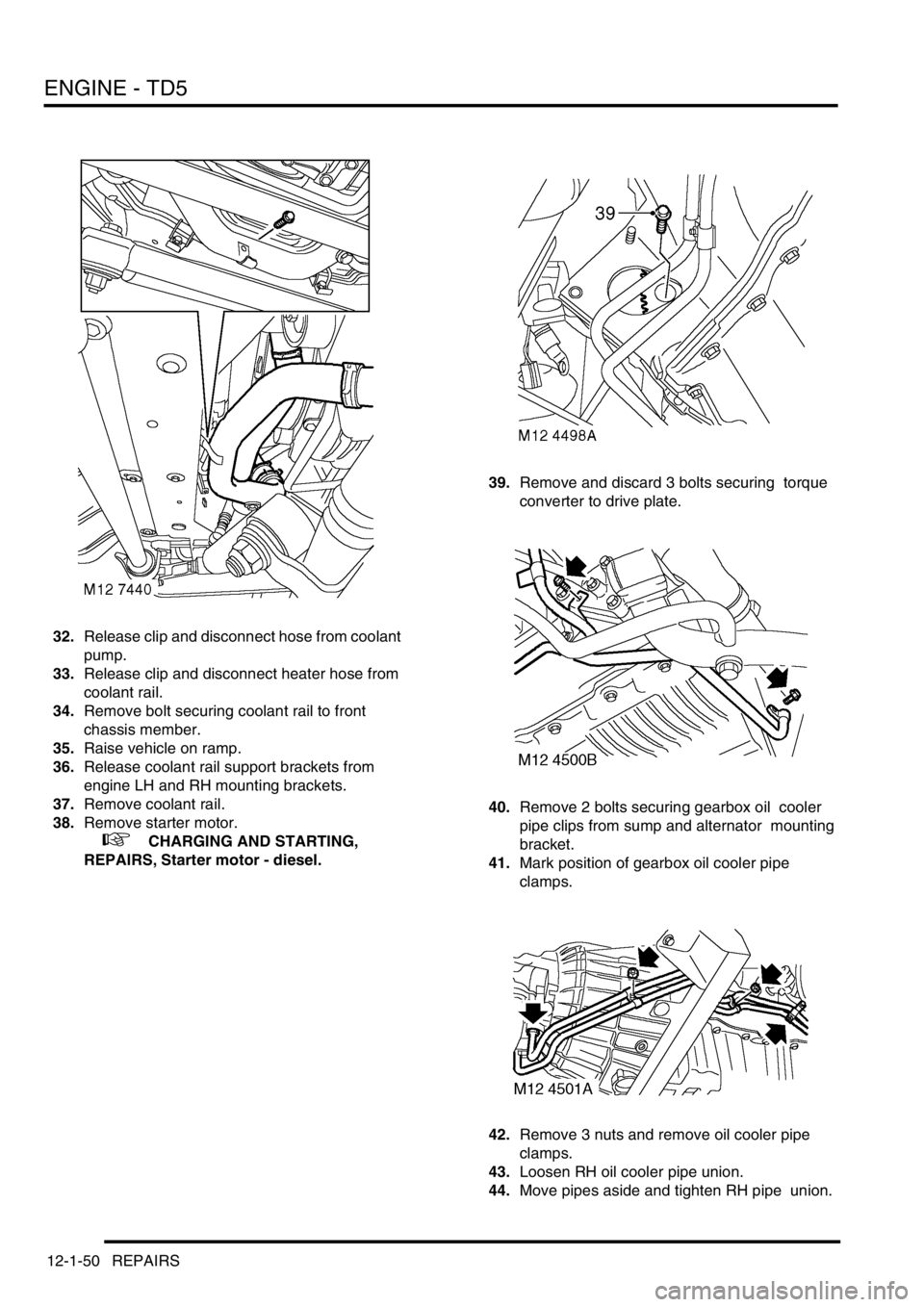
32.Release clip and disconnect hose from coolant
pump.
33.Release clip and disconnect heater hose from
coolant rail.
34.Remove bolt securing coolant rail to front
chassis member.
35.Raise vehicle on ramp.
36.Release coolant rail support brackets from
engine LH and RH mounting brackets.
37.Remove coolant rail.
38.Remove starter motor.
+ CHARGING AND STARTING,
REPAIRS, Starter motor - diesel.39.Remove and discard 3 bolts securing torque
converter to drive plate.
40.Remove 2 bolts securing gearbox oil cooler
pipe clips from sump and alternator mounting
bracket.
41.Mark position of gearbox oil cooler pipe
clamps.
42.Remove 3 nuts and remove oil cooler pipe
clamps.
43.Loosen RH oil cooler pipe union.
44.Move pipes aside and tighten RH pipe union.