fuel tank removal LAND ROVER DISCOVERY 2002 Workshop Manual
[x] Cancel search | Manufacturer: LAND ROVER, Model Year: 2002, Model line: DISCOVERY, Model: LAND ROVER DISCOVERY 2002Pages: 1672, PDF Size: 46.1 MB
Page 51 of 1672

GENERAL INFORMATION
03-16
Fuel Handling Precautions
Fuel vapour is highly flammable and in confined
spaces is also explosive and toxic. The vapour is
heavier than air and will always fall to the lowest
level. The vapour can be easily distributed
throughout a workshop by air currents;
consequently, even a small spillage of fuel is
potentially very dangerous.
The following information provides basic precautions
which must be observed if fuel is to be handled
safely. It also outlines other areas of risk which must
not be ignored. This information is issued for basic
guidance only, if in doubt consult your local Fire
Officer.
General
Always have a fire extinguisher containing FOAM,
CO
2, GAS or POWDER close at hand when handling
or draining fuel or when dismantling fuel systems.
Fire extinguishers should also be located in areas
where fuel containers are stored.
Always disconnect the vehicle battery before
carrying out dismantling or draining work on a fuel
system.
Whenever fuel is being handled, drained or stored, or
when fuel systems are being dismantled, all forms of
ignition must be extinguished or removed; any
leadlamps must be flameproof and kept clear of
spillage.
WARNING: No one should be permitted to repair
components associated with fuel without first
having specialist training.
WARNING: Do not remove fuel system
components while the vehicle is over a pit.
Fuel tank draining
Fuel tank draining should be carried out in
accordance with the procedure outlined in the FUEL
DELIVERY section of this manual and observing the
following precautions.
WARNING: Fuel must not be extracted or drained
from any vehicle while it is over a pit. Extraction
or draining of fuel must be carried out in a well
ventilated area.
The capacity of containers must be more than
adequate for the amount of fuel to be extracted or
drained. The container should be clearly marked
with its contents and placed in a safe storage
area which meets the requirements of local
authority regulations.Fuel tank removal
When the fuel line is secured to the fuel tank outlet by
a spring steel clip, the clip must be released before
the fuel line is disconnected or the fuel tank is
removed. This procedure will avoid the possibility of
fumes in the fuel tank being ignited when the clip is
released.
As an added precaution, fuel tanks should have a
'FUEL VAPOUR' warning label attached to them as
soon as they are removed from the vehicle.
Fuel tank repairs - plastic tank
No attempt should be made to repair a plastic fuel
tank. If the structure of the tank is damaged, a new
tank must be fitted.
Body repairs
Plastic fuel pipes are particularly susceptible to heat,
even at relatively low temperature, and can be
melted by heat conducted from some distance away.
When body repairs involve the use of heat, all fuel
pipes which run in the vicinity of the repair area must
be removed, and the tank outlet plugged.
WARNING: If welding is to be carried out in the
vicinity of the fuel tank, the fuel system must be
drained and the tank removed before welding
commences.
Page 550 of 1672

FUEL DELIVERY SYSTEM - TD5
DESCRIPTION AND OPERATION 19-1-5
The fuel pump is a 'self priming', wet type, two stage pump which is immersed in fuel in the tank and operates at all
times when the ignition switch is in position II. If the engine is not started, the ECU will 'time-out' after three minutes
and de-energise the fuel pump relay. The pump receives a feed from the battery via fuse 10 in the engine
compartment fusebox and the fuel pump relay. The relay is energised by the ECM when the ignition switch is moved
to position II.
The fuel pump assembly is retained with a locking ring and sealed with a rubber seal. The locking ring requires a
special tool for removal and refitment. An access panel for the fuel pump is located in the loadspace floor below the
carpet. The access panel is sealed to the floor with a rubber seal and retained by six self-tapping screws. A four pin
electrical connector is located on the top cover and provides power feed and earth for the fuel pump and also inputs
and outputs for the fuel gauge sender operation.
The fuel gauge sender is integral with the fuel pump. The sender is submerged in the fuel and is operated by a float
which moves with the fuel level in the tank.
Fuel pump
The fuel pump assembly comprises a top cover which locates the electrical connector, fuel burning heater connection
and four fuel pipe couplings. The top cover is attached to a plastic cup shaped housing and retained on three sliding
clips. Two coil springs are located between the cover and the housing and ensure that the fuel pump remains seated
positively at the bottom of the tank when installed.
The housing locates the two stage fuel pump and also the fuel gauge sender unit. The lower part of the housing is the
swirl pot which maintains a constant level of fuel at the fuel pick-up. A coarse filter is located in the base of the housing
and prevents the ingress of contaminants into the pump and the fuel system from the fuel being drawn into the pump.
A fine filter is located in the intake to the low pressure stage to protect the pump from contaminants. Flexible pipes
connect the couplings on the top cover to the pump.
A non-return valve is located in the base of the housing. When the fuel tank is full, fuel pressure keeps the valve lifted
from its seat allowing fuel to flow into the swirl pot. As the tank level reduces, the fuel pressure in the tank reduces
causing the valve to close. When the valve is closed fuel is retained in the swirl pot, ensuring that the swirl pot remains
full and maintains a constant supply to the fuel pump.
The two stage pump comprises a high and a low pressure stage. The low pressure stage draws fuel from the swirl
pot through the filter. The low pressure stage pumps fluid at a pressure of 0.75 bar (10.9 lbf.in
2) and a flow of 30 litres/
hour (8 US Gallons/hour) to the fuel filter. A proportion of the fuel from the low pressure stage also passes, via a
restrictor, through a jet pump which keeps fuel circulating in the swirl pot. The high pressure stage draws the low
pressure fuel from the fuel filter and pressurises it to a pressure of 4.0 bar (58 lbf.in
2). The pressurised fuel is then
passed from the pump to the injectors at a flow of 180 litres/hour (47.6 US Gallons/hour). A fuel pressure regulator is
located at the rear of the engine and ensures that the delivery pressure remains at 4.0 bar (58 lbf.in
2) by controlling
the amount of fuel returning to the fuel tank.
The fuel pump has a maximum current draw of 15 Amps at 12.5 V and is protected by a 20 Amp fuse in the engine
compartment fusebox.
Page 571 of 1672

FUEL DELIVERY SYSTEM - V8
19-2-6 DESCRIPTION AND OPERATION
The filler cap operated valve closes the vent line to the EVAP canister to prevent the customer trickle filling the tank.
Trickle filling greatly reduces the vapour space in the tank which in turn affects the tank's ability to breathe properly,
reducing engine performance and safety. When filling the tank, the removal of the filler cap closes the valve and the
vent line preventing the customer from trickle filling the tank. When the cap is installed the valve is opened by the cap
allowing vapour to vent to the EVAP canister.
The four ROV's are welded inside the top surface of the tank. Each ROV is connected internally in the tank by a tube
to the LVS. The ROV's allow fuel vapour to pass through them during normal vehicle operation. In the event of the
vehicle being overturned the valves shut-off, sealing the tank and preventing fuel from spilling from the vent line into
the LVS.
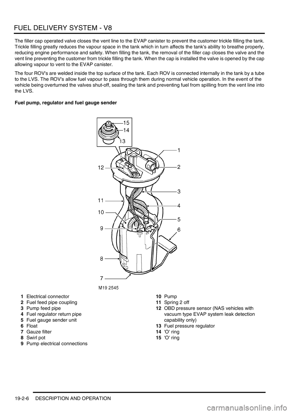
Fuel pump, regulator and fuel gauge sender
1Electrical connector
2Fuel feed pipe coupling
3Pump feed pipe
4Fuel regulator return pipe
5Fuel gauge sender unit
6Float
7Gauze filter
8Swirl pot
9Pump electrical connections10Pump
11Spring 2 off
12OBD pressure sensor (NAS vehicles with
vacuum type EVAP system leak detection
capability only)
13Fuel pressure regulator
14'O' ring
15'O' ring
Page 572 of 1672

FUEL DELIVERY SYSTEM - V8
DESCRIPTION AND OPERATION 19-2-7
The fuel pump is a 'self priming' wet type pump which is immersed in fuel in the tank. The fuel pump operates at all
times when the ignition switch is in position II. If the engine is not started, the ECU will 'time-out' after 2 seconds and
de-energise the fuel pump relay to protect the pump. The pump receives a feed from the battery via fuse 10 in the
engine compartment fusebox and the fuel pump relay. The relay is energised by the ECM when the ignition switch is
moved to position II.
The fuel pump is retained with a locking ring and sealed with a rubber seal. The locking ring requires a special tool
for removal and fitment. An access panel for the fuel pump is located in the loadspace floor below the loadspace
carpet. The access panel is sealed to the floor with a rubber seal and retained by six self-tapping screws.
The fuel gauge sender is integral with the fuel pump. The sender is submerged in the fuel and is operated by a float
which moves with the fuel level in the tank.
Fuel pump
The fuel pump assembly comprises a top cover which locates the fuel pressure regulator, electrical connector and
fuel pipe coupling. The top cover is attached to a plastic cup shaped housing by two metal springs. The housing
locates the pump and the fuel gauge sender unit.
The lower part of the housing is the swirl pot, which maintains a constant fuel level at the fuel pick-up. A feed pipe
from the pump to the coupling connection and a return pipe from the regulator connect between the top cover and the
housing.
A coarse filter is attached to the base of the housing and prevents the ingress of large contaminants into the swirl pot.
A gauze filter prevents particles entering the fuel pump.
Surrounding the pump is a large fine paper filter element which further protects the fuel pressure regulator, engine
and injectors from particulate contamination. The paper filter is not a serviceable item and removes the requirement
for an external in-line filter.
A non-return valve is located in the base of the housing. When the fuel tank is full, fuel pressure keeps the valve lifted
from its seat allowing fuel to flow into the swirl pot. As the tank level reduces, the fuel pressure in the tank reduces
causing the valve to close. When the valve is closed fuel is retained in the swirl pot, ensuring that the swirl pot remains
full and maintains a constant supply to the fuel pump.
A four pin electrical connector is located on the top cover of the pump and provides power feed and return for fuel
pump and fuel gauge rotary potentiometer operation. A single quick release coupling connects the fuel feed pipe to
the outer top surface of the pump.
Two metal springs are attached to the top cover and the housing of the pump. When the pump is installed it seats on
the lower surface inside the tank. The springs exert a downward pressure on the pump and ensure that the pump is
located positively at the bottom of the fuel tank.
The fuel pump has a maximum current draw of 6.5 A at 12.5 V.
On NAS vehicles with vacuum type EVAP system leak detection capability only, the fuel pump top cover is fitted with
an On Board Diagnostics (OBD) pressure sensor. This sensor has a three pin electrical connector which provides a
connection between the sensor and the ECM. The sensor is sealed in the top cover with an 'O' ring and secured with
a clip. The sensor monitors tank pressure during OBD tests of the fuel evaporation system integrity. A hose is
connected to the sensor and is routed across the top of the fuel tank and terminates at the top of the fuel filler tube.
The pipe is open to atmosphere and provides atmospheric pressure for the sensor operation.
+ ENGINE MANAGEMENT SYSTEM - V8, DESCRIPTION AND OPERATION, Description - engine
management.
Page 1322 of 1672

CORROSION PREVENTION AND SEALING
CORROSION PREVENTION 77-4-7
The checks described above are intended to be visual only. It is not intended that the operator should remove trim
panels, finishers, rubbing strips or sound-deadening materials when checking the vehicle for corrosion and paint
damage.
With the vehicle on a lift, and using an inspection or spot lamp, visually check for the following:
lCorrosion damage and damaged paintwork, condition of underbody sealer on front and rear lower panels, sills
and wheel arches;
lDamage to underbody sealer. Corrosion in areas adjacent to suspension mountings and fuel tank fixings.
NOTE: The presence of small blisters in the underbody sealer is acceptable, providing they do not expose bare metal.
Pay special attention to signs of damage caused to panels or corrosion protection material by incorrect jack
positioning.
WARNING: It is essential to follow the correct jacking and lifting procedures.
With the vehicle lowered, visually check for evidence of damage and corrosion on all visible painted areas, in
particular the following:
lFront edge of bonnet;
lVisible flanges in engine compartment;
lLower body and door panels.
Rectify any bodywork damage or evidence of corrosion found during inspection as soon as is practicable, both to
minimise the extent of the damage and to ensure the long term effectiveness of the factory-applied corrosion
prevention treatment. Where the cost of rectification work is the owner's responsibility, the Dealer must advise the
owner and endorse the relevant documentation accordingly.
Where corrosion has become evident and is emanating from beneath a removable component (e.g. trim panel,
window glass, seat etc.), remove the component as required to permit effective rectification.
Underbody protection repairs
Whenever body repairs are carried out, ensure that full sealing and corrosion protection treatments are reinstated.
This applies both to the damaged areas and also to areas where protection has been indirectly impaired, as a result
either of accident damage or repair operations.
Remove corrosion protection from the damaged area before straightening or panel beating. This applies in particular
to panels coated with wax, PVC underbody sealer, sound deadening pads etc.
WARNING: DO NOT use oxy-acetylene gas equipment to remove corrosion prevention materials. Large
volumes of fumes and gases are liberated by these materials when they burn.
NOTE: Equipment for the removal of tough anti-corrosion sealers offers varying degrees of speed and effectiveness.
The compressed air-operated scraper (NOT an air chisel) offers a relatively quiet mechanical method using an
extremely rapid reciprocating action. Move the operating end of the tool along the work surface to remove the material.
The most common method of removal is by means of a hot air blower with integral scraper.
Another tool, and one of the most efficient methods, is the rapid-cutting 'hot knife'. This tool uses a wide blade and is
quick and versatile, able to be used easily in profiled sections where access is otherwise difficult.
Use the following procedure when repairing underbody coatings:
1Remove existing underbody coatings
2After panel repair, clean the affected area with a solvent wipe, and treat bare metal with an etch phosphate
material
3Re-prime the affected area
CAUTION: DO NOT, under any circumstances, apply underbody sealer directly to bare metal surfaces.
4Replace all heat-fusible plugs which have been disturbed. Where such plugs are not available use rubber
grommets of equivalent size, ensuring that they are embedded in sealer
5Mask off all mounting faces from which mechanical components, hoses and pipe clips, have been removed.
Underbody sealer must be applied before such components are refitted
6Brush sealer into all exposed seams
7Spray the affected area with an approved service underbody sealer
8Remove masking from component mounting faces, and touch-in where necessary. Allow adequate drying time
before applying underbody wax