service LAND ROVER DISCOVERY 2002 Workshop Manual
[x] Cancel search | Manufacturer: LAND ROVER, Model Year: 2002, Model line: DISCOVERY, Model: LAND ROVER DISCOVERY 2002Pages: 1672, PDF Size: 46.1 MB
Page 30 of 1672
INTRODUCTION
01-1
INTRODUCTION
How To Use This Manual
General
To assist in the use of this Manual, it is divided into
sections and sub-sections. The section title is given
at the top of each page and the relevant sub-section
is given at the bottom.
There is a single contents section at the front of the
Manual, which is divided by section and sub-section.
Each section is numbered from page 1.
The individual items comprising repair operations are
to be followed in the sequence in which they appear.
Items numbers in the illustration are referred to in the
text.
Adjustment and Repair operations include reference
to Service tool numbers and the associated
illustration depicts the tool in use. Adjustment and
repair operations also include reference to wear
limits, relevant data, torque figures, and specialist
information and useful assembly details. Each
adjustment or repair operation is given its Service
Repair Operation number.
WARNINGS, CAUTIONS and NOTES have the
following meanings:
WARNING: Procedures which must be followed
precisely to avoid the possibility of injury.
CAUTION: Calls attention to procedures which
must be followed to avoid damage to
components.
NOTE: Gives helpful information.
References
References to the LH or RH side given in this Manual
are made when viewing the vehicle from the rear.
With the engine and gearbox assembly removed, the
crankshaft pulley end of the engine is referred to as
the front.
Operations covered in this Manual do not include
reference to testing the vehicle after repair. It is
essential that work is inspected and tested after
completion and if necessary a road test of the vehicle
is carried out particularly where safety related items
are concerned.
Dimensions
The dimensions quoted are to design engineering
specification with Service limits where applicable.
Repairs and Replacements
When replacement parts are required it is essential
that only Land Rover recommended parts are used.
Attention is particularly drawn to the following points
concerning repairs and the fitting of replacement
parts and accessories.
Safety features and corrosion prevention treatments
embodied in the vehicle may be impaired if other
than Land Rover recommended parts are fitted. In
certain territories, legislation prohibits the fitting of
parts not to the manufacturer's specification. Torque
wrench setting figures given in this Manual must be
used. Locking devices, where specified, must be
fitted. If the efficiency of a locking device is impaired
during removal it must be renewed.
Owners purchasing accessories while travelling
abroad should ensure that the accessory and its
fitted location on the car conform to legal
requirements.
The Terms of the vehicle Warranty may be
invalidated by the fitting of parts other than Land
Rover recommended parts.
All Land Rover recommended parts have the full
backing of the vehicle Warranty.
Land Rover Dealers are obliged to supply only Land
Rover recommended parts.
Page 33 of 1672

INTRODUCTION
01-4
HRW Heated Rear Window
HSLA High Strength Low Alloy
ht/HT High tension
IACV Idle Air Control Valve
IAT Intake Air Temperature
ICE In-Car Entertainment
i.dia. Internal diameter
IDM Intelligent Driver Module
IF Intermediate Frequency
in
3Cubic inch
ILT Inlet Throttle
IPW Injector Pulse Width
ISO International Organisation for
Standardisation
ITS Inflatable Tubular Structure
k Thousand
kg Kilogramme
kg/h Kilogrammes per hour
km Kilometre
km/h Kilometres per hour
kPa KiloPascal
KS Knock Sensor
lb(s) Pounds
lbf Pounds force
lbf.in Pounds force inches
lbf/in
2Pounds per square inch
lbf.ft Pounds force feet
λLambda
lc Low compression
LCD Liquid Crystal Display
LED Light Emitting Diode
LEV Low Emission Vehicle
LH Left-Hand
LHD Left-Hand Drive
LSM Light Switch Module
LVS Liquid Vapour Separator
mMetre
µMicro
MAF Mass Air Flow
MAP Manifold Absolute Pressure
MET Mechanical, Electrical and Trim
MFU Multi-Function Unit
MFL Multi-Function Logic
max. Maximum
MEMS Modular Engine Management
System
MIG Metal/Inert Gas
MIL Malfunction Indicator Lamp
MPa MegaPascal
MOSFET Metal Oxide Semiconductor Field
Effect Transistor
min. Minimum
- Minus (tolerance)
' Minute (angle)
mm Millimetre
mph Miles per hour MPi Multi-Point injection
MV Motorised Valve
MY Model Year
NAS North American Specification
(-) Negative (electrical)
Nm Newton metre
No. Number
NO
2Nitrogen Dioxide
NO
xOxides of Nitrogen
NTC Negative Temperature
Coefficient
NRV Non Return Valve
OBD On Board Diagnostics
OBM On Board Monitoring
o.dia. Outside diameter
OAT Organic Acid Technology
ORM Off-road Mode
ΩOhm
PAS Power Assisted Steering
PCB Printed Circuit Board
PCV Positive Crankcase Ventilation
PDC Parking Distance Control
PDOP Position Dilation Of Precision
PI Programme Information
PPS Pulse Per Second
PS Programme Service
psi Pounds per square inch
pts. Pints
% Percentage
+ Plus (tolerance) or Positive
(electrical)
±Plus or minus (tolerance)
PTC Positive Temperature Coefficient
PTFE Polytetrafluorethylene
PVC Polyvinyl chloride
PWM Pulse Width Modulation
RDS Radio Data Service
rRadius
:Ratio
ref Reference
REG Regionalisation
RES Rover Engineering Standards
rev/min Revolutions per minute
RF Radio Frequency
RGB Red / Green / Blue
RH Right-Hand
RHD Right-Hand Drive
ROM Read Only Memory
RON Research Octane Number
ROV Roll Over Valve
ROW Rest Of World
SAE Society of Automotive Engineers
SAI Secondary Air Injection
" Second (angle)
SLABS Self Levelling and Anti-Lock
Brake System
SLS Self Levelling Suspension
SOHC Single Overhead Camshaft
Page 41 of 1672

GENERAL INFORMATION
03-6
General Fitting Instructions
Component removal
Whenever possible, clean components and
surrounding area before removal.
lBlank off openings exposed by component
removal.
lImmediately seal fuel, oil or hydraulic lines when
apertures are exposed; use plastic caps or
plugs to prevent loss of fluid and ingress of dirt.
lClose the open ends of oilways exposed by
component removal with tapered hardwood
plugs or conspicuous plastic plugs.
lImmediately a component is removed, place it in
a suitable container; use a separate container
for each component and its associated parts.
lClean bench and provide marking materials,
labels and containers before dismantling a
component.
Dismantling
Observe scrupulous cleanliness when dismantling
components, particularly when brake, fuel or
hydraulic system parts are being worked on. A
particle of dirt or a cloth fragment could cause a
serious malfunction if trapped in these systems.
lBlow out all tapped holes, crevices, oilways and
fluid passages with an air line. Ensure that any
'O' rings used for sealing are correctly replaced
or renewed, if disturbed during the process.
lUse marking ink to identify mating parts and
ensure correct reassembly. Do not use a centre
punch or scriber to mark parts, they could
initiate cracks or distortion in marked
components.
lWire together mating parts where necessary to
prevent accidental interchange (e.g. roller
bearing components).
lWire labels on to all parts which are to be
renewed, and to parts requiring further
inspection before being passed for reassembly;
place these parts in separate containers from
those containing parts for rebuild.
lDo not discard a part due for renewal until after
comparing it with a new part, to ensure that its
correct replacement has been obtained.Cleaning components
Always use the recommended cleaning agent or
equivalent. Ensure that adequate ventilation is
provided when volatile degreasing agents are being
used. Do not use degreasing equipment for
components containing items which could be
damaged by the use of this process.
General inspection
All components should be inspected for wear or
damage before being reassembled.
lNever inspect a component for wear or
dimensional check unless it is absolutely clean;
a slight smear of grease can conceal an
incipient failure.
lWhen a component is to be checked
dimensionally against recommended values,
use the appropriate measuring equipment
(surface plates, micrometers, dial gauges etc.).
Ensure the measuring equipment is calibrated
and in good serviceable condition.
lReject a component if its dimensions are
outside the specified tolerances, or if it appears
to be damaged.
lA part may be refitted if its critical dimension is
exactly to its tolerance limit and it appears to be
in satisfactory condition. Use 'Plastigauge' 12
Type PG-1 for checking bearing surface
clearances.
Page 42 of 1672
GENERAL INFORMATION
03-7
Ball and Roller Bearings
General
When removing and installing bearings, ensure that
the following practices are observed to ensure
component serviceability.
lRemove all traces of lubricant from bearing
under inspection by cleaning with a suitable
degreasant; maintain absolute cleanliness
throughout operations.
lConduct a visual inspection for markings on
rolling elements, raceways, outer surface of
outer rings or inner surface of inner rings. Reject
any bearings found to be marked, since marking
in these areas indicates onset of wear.
lHold inner race of bearing between finger and
thumb of one hand and spin outer race to check
that it revolves absolutely smoothly. Repeat,
holding outer race and spinning inner race.
lRotate outer ring gently with a reciprocating
motion, while holding inner ring; feel for any
check or obstruction to rotation. Reject bearing
if action is not perfectly smooth.
lLubricate bearing with generous amounts of
lubricant appropriate to installation.
lInspect shaft and bearing housing for
discoloration or other markings which indicate
movement between bearing and seatings.
lEnsure that shaft and housing are clean and
free from burrs before fitting bearing.
lIf one bearing of a pair shows an imperfection, it
is advisable to replace both with new bearings;
an exception could be if the faulty bearing had
covered a low mileage, and it can be
established that damage is confined to only one
bearing.
lNever refit a ball or roller bearing without first
ensuring that it is in a fully serviceable condition.
lWhen hub bearings are removed or displaced,
new bearings must be fitted; do not attempt to
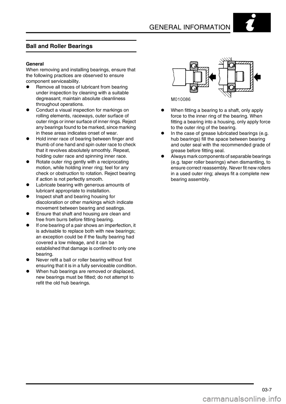
refit the old hub bearings.lWhen fitting a bearing to a shaft, only apply
force to the inner ring of the bearing. When
fitting a bearing into a housing, only apply force
to the outer ring of the bearing.
lIn the case of grease lubricated bearings (e.g.
hub bearings) fill the space between bearing
and outer seal with the recommended grade of
grease before fitting seal.
lAlways mark components of separable bearings
(e.g. taper roller bearings) when dismantling, to
ensure correct reassembly. Never fit new rollers
in a used outer ring; always fit a complete new
bearing assembly.
Page 43 of 1672
GENERAL INFORMATION
03-8
Oil Seals
General
Always renew oil seals which have been removed
from their working location (whether as an individual
component or as part of an assembly). NEVER use
a seal which has been improperly stored or handled,
such as hung on a hook or nail.
lCarefully examine seal before fitting to ensure
that it is clean and undamaged.
lEnsure the surface on which the new seal is to
run is free of burrs or scratches. Renew the
component if the original sealing surface cannot
be completely restored.
lProtect the seal from any surface which it has to
pass when being fitted. Use a protective sleeve
or tape to cover the relevant surface.
lLubricate the sealing lips with a recommended
lubricant before use to prevent damage during
initial use. On dual lipped seals, smear the area
between the lips with grease.
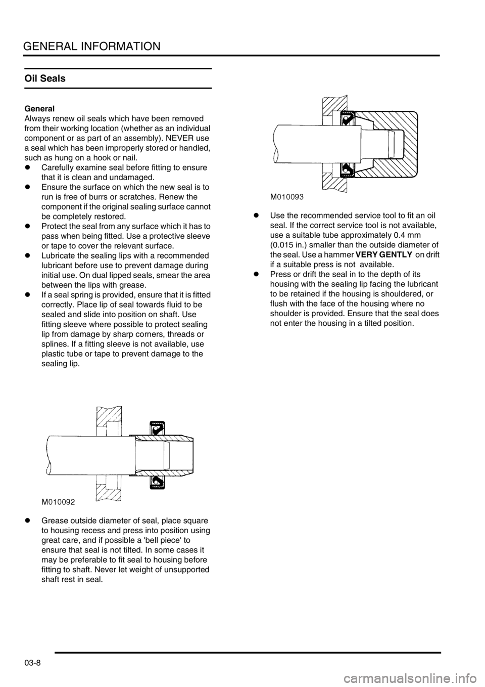
lIf a seal spring is provided, ensure that it is fitted
correctly. Place lip of seal towards fluid to be
sealed and slide into position on shaft. Use
fitting sleeve where possible to protect sealing
lip from damage by sharp corners, threads or
splines. If a fitting sleeve is not available, use
plastic tube or tape to prevent damage to the
sealing lip.
lGrease outside diameter of seal, place square
to housing recess and press into position using
great care, and if possible a 'bell piece' to
ensure that seal is not tilted. In some cases it
may be preferable to fit seal to housing before
fitting to shaft. Never let weight of unsupported
shaft rest in seal.lUse the recommended service tool to fit an oil
seal. If the correct service tool is not available,
use a suitable tube approximately 0.4 mm
(0.015 in.) smaller than the outside diameter of
the seal. Use a hammer VERY GENTLY on drift
if a suitable press is not available.
lPress or drift the seal in to the depth of its
housing with the sealing lip facing the lubricant
to be retained if the housing is shouldered, or
flush with the face of the housing where no
shoulder is provided. Ensure that the seal does
not enter the housing in a tilted position.
Page 48 of 1672
GENERAL INFORMATION
03-13
Self-locking nuts
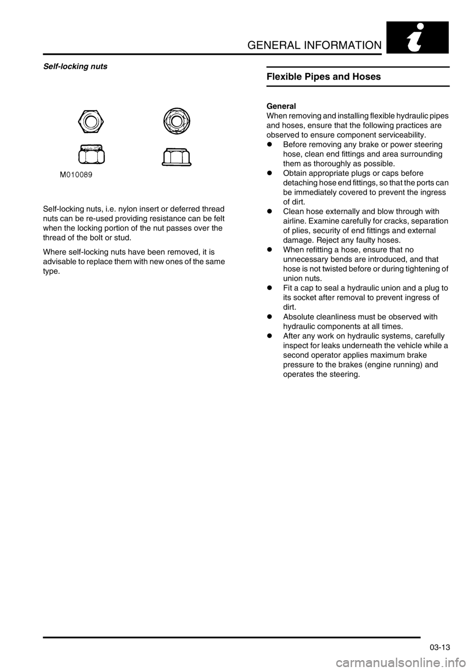
Self-locking nuts, i.e. nylon insert or deferred thread
nuts can be re-used providing resistance can be felt
when the locking portion of the nut passes over the
thread of the bolt or stud.
Where self-locking nuts have been removed, it is
advisable to replace them with new ones of the same
type.
Flexible Pipes and Hoses
General
When removing and installing flexible hydraulic pipes
and hoses, ensure that the following practices are
observed to ensure component serviceability.
lBefore removing any brake or power steering
hose, clean end fittings and area surrounding
them as thoroughly as possible.
lObtain appropriate plugs or caps before
detaching hose end fittings, so that the ports can
be immediately covered to prevent the ingress
of dirt.
lClean hose externally and blow through with
airline. Examine carefully for cracks, separation
of plies, security of end fittings and external
damage. Reject any faulty hoses.
lWhen refitting a hose, ensure that no
unnecessary bends are introduced, and that
hose is not twisted before or during tightening of
union nuts.
lFit a cap to seal a hydraulic union and a plug to
its socket after removal to prevent ingress of
dirt.
lAbsolute cleanliness must be observed with
hydraulic components at all times.
lAfter any work on hydraulic systems, carefully
inspect for leaks underneath the vehicle while a
second operator applies maximum brake
pressure to the brakes (engine running) and
operates the steering.
Page 52 of 1672
GENERAL INFORMATION
03-17
Electrical Precautions
General
The following guidelines are intended to ensure the
safety of the operator while preventing damage to the
electrical and electronic components fitted to the
vehicle. Where necessary, specific precautions are
detailed in the individual procedures of this manual.
Equipment
Prior to commencing any test procedure on the
vehicle ensure that the relevant test equipment is
working correctly and any harness or connectors are
in good condition. It is particularly important to check
the condition of the lead and plugs of mains operated
equipment.
Polarity
Never reverse connect the vehicle battery and
always ensure the correct polarity when connecting
test equipment.
High voltage circuits
Whenever disconnecting live ht circuits always use
insulated pliers and never allow the open end of the
ht lead to contact other components, particularly
ECU's. Exercise caution when measuring the voltage
on the coil terminals while the engine is running, high
voltage spikes can occur on these terminals.
Connectors and harnesses
The engine compartment of a vehicle is a particularly
hostile environment for electrical components and
connectors:
lAlways ensure electrically related items are dry
and oil free before disconnecting and
connecting test equipment.
lEnsure disconnected multiplugs and sensors
are protected from being contaminated with oil,
coolant or other solutions. Contamination could
impair performance or result in catastrophic
failure.
lNever force connectors apart using tools to
prise apart or by pulling on the wiring harness.
lAlways ensure locking tabs are disengaged
before disconnection, and match orientation to
enable correct reconnection.
lEnsure that any protection (covers, insulation
etc.) is replaced if disturbed.Having confirmed a component to be faulty:
lSwitch off the ignition and disconnect the
battery.
lRemove the component and support the
disconnected harness.
lWhen replacing the component keep oily hands
away from electrical connection areas and push
connectors home until any locking tabs fully
engage.
Battery disconnection
Before disconnecting the battery, disable the alarm
system and switch off all electrical equipment. If the
radio is to be serviced, ensure the security code has
been deactivated.
CAUTION: To prevent damage to electrical
components, always disconnect the battery
when working on the vehicle's electrical system.
The ground lead must be disconnected first and
reconnected last.
CAUTION: Always ensure that battery leads are
routed correctly and are not close to any
potential chafing points.
Battery charging
Only recharge the battery with it removed from the
vehicle. Always ensure any battery charging area is
well ventilated and that every precaution is taken to
avoid naked flames and sparks.
Ignition system safety precautions
The vehicle's ignition system produces high voltage
and the following precautions should be observed
before carrying out any work on the system.
WARNING: Before commencing work on an
ignition system, ensure all high tension
terminals, adapters and diagnostic equipment
are adequately insulated and shielded to prevent
accidental personal contacts and minimise the
risk of shock. Wearers of surgically implanted
pacemaker devices should not be in close
proximity of ignition circuits or diagnostic
equipment.
Disciplines
Switch off the ignition prior to making any connection
or disconnection in the system to prevent electrical
surges caused by disconnecting 'live' connections
damaging electronic components.
Ensure hands and work surfaces are clean and free
of grease, swarf, etc. Grease collects dirt which can
cause electrical tracking (short-circuits) or high-
resistance contacts.
When handling printed circuit boards, treat with care
and hold by the edges only; note that some electronic
components are susceptible to body static.
Page 53 of 1672
GENERAL INFORMATION
03-18
Connectors should never be subjected to forced
removal or refit, especially inter-board connectors.
Damaged contacts can cause short-circuit and open-
circuit fault conditions.
Prior to commencing test, and periodically during a
test, touch a good vehicle body earth to discharge
static charge. Some electronic components are
vulnerable to the static electricity that may be
generated by the operator.
Grease for electrical connectors
Some under bonnet and under body connectors may
be protected against corrosion by the application of a
special grease during vehicle production. Should
connectors be disturbed in service, repaired or
replaced, additional grease should be applied: Part
No. BAU 5811, available in 150 gm tubs.
NOTE: The use of greases other than BAU 5811
must be avoided as they can migrate into relays,
switches etc. contaminating the contacts and leading
to intermittent operation or failure.
Supplementary Restraint System
Precautions
General
The Supplementary Restraint System (SRS)
provides active protection for vehicle occupants in
the event of a serious collision. The system
components include airbags and pretensioner seat
belts which are automatically deployed when a
severe frontal crash condition is detected.
In order to assure system integrity, it is essential that
the SRS system is regularly checked and maintained
so that it is ready for operation in the event of an
accident.
The SRS system contains components which could
be potentially hazardous to the service engineer if
not serviced and handled correctly. The following
guidelines are intended to alert the service engineer
to potential sources of danger and emphasise the
importance of ensuring integrity of the SRS
components fitted to the vehicle.
Where necessary, additional specific precautions are
detailed in the Restraint Systems section of this
Manual which should be referred to prior to
commencing repair operations.
It should be noted that these precautions are not
restricted to operations performed when servicing
the SRS system. The same care should be exercised
when working on ancillary systems and components
located in the vicinity of SRS components; these
include but are not limited to steering system (driver's
airbag), body and trim components (passenger's
airbag and seat belt pretensioners) and electrical
system components (SRS harnesses etc.).
Page 55 of 1672
GENERAL INFORMATION
03-20
Storage
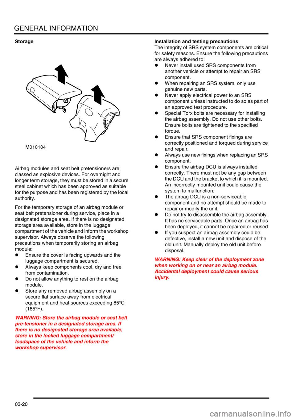
Airbag modules and seat belt pretensioners are
classed as explosive devices. For overnight and
longer term storage, they must be stored in a secure
steel cabinet which has been approved as suitable
for the purpose and has been registered by the local
authority.
For the temporary storage of an airbag module or
seat belt pretensioner during service, place in a
designated storage area. If there is no designated
storage area available, store in the luggage
compartment of the vehicle and inform the workshop
supervisor. Always observe the following
precautions when temporarily storing an airbag
module:
lEnsure the cover is facing upwards and the
luggage compartment is secured.
lAlways keep components cool, dry and free
from contamination.
lDo not allow anything to rest on the airbag
module.
lStore any removed airbag assembly on a
secure flat surface away from electrical
equipment and heat sources exceeding 85
°C
(185
°F).
WARNING: Store the airbag module or seat belt
pre-tensioner in a designated storage area. If
there is no designated storage area available,
store in the locked luggage compartment/
loadspace of the vehicle and inform the
workshop supervisor.Installation and testing precautions
The integrity of SRS system components are critical
for safety reasons. Ensure the following precautions
are always adhered to:
lNever install used SRS components from
another vehicle or attempt to repair an SRS
component.
lWhen repairing an SRS system, only use
genuine new parts.
lNever apply electrical power to an SRS
component unless instructed to do so as part of
an approved test procedure.
lSpecial Torx bolts are necessary for installing
the airbag assembly. Do not use other bolts.
Ensure bolts are tightened to the specified
torque.
lEnsure that SRS component fixings are
correctly positioned and torqued during service
and repair.
lAlways use new fixings when replacing an SRS
component.
lEnsure the airbag DCU is always installed
correctly. There must not be any gap between
the DCU and the bracket to which it is mounted.
An incorrectly mounted unit could cause the
system to malfunction.
lThe airbag DCU is a non-serviceable
component and no attempt should be made to
repair or modify the unit.
lDo not try to disassemble the airbag assembly.
It has no serviceable parts. Once an airbag has
been deployed, it cannot be repaired or reused.
lIf you suspect an airbag assembly could be
defective, install a new unit and dispose of the
old unit. Manually deploy the old unit before
disposal.
WARNING: Keep clear of the deployment zone
when working on or near an airbag module.
Accidental deployment could cause serious
injury.
Page 57 of 1672
GENERAL INFORMATION
03-22
Rotary coupler
Always follow the Repair procedure for fitting the
rotary coupler.
Comply with all safety and installation procedures to
ensure the system functions correctly. Observe the
following precautions:
lDo not install a rotary coupler if it is suspected to
be defective.
lDo not attempt to service, modify or repair a
rotary coupler.
lDo not cut, splice or modify the wires attached
to yellow SRS connector and lead.
lAlways ensure the rotary coupler connectors
are mated correctly and securely fastened.
lAlways ensure the battery is disconnected
before working on the rotary coupler.
lAlways ensure the rotary coupler is removed
and installed in its centered position and with the
front road wheels in the straight ahead position.
lIf a new rotary coupler is being installed, ensure
the locking tab holding the coupler's rotational
position is not broken; units with a broken
locking tab should not be used.
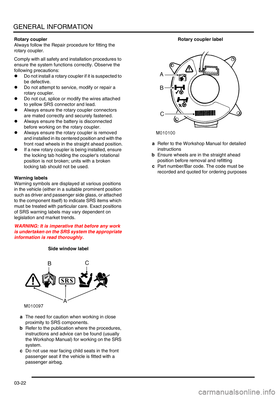
Warning labels
Warning symbols are displayed at various positions
in the vehicle (either in a suitable prominent position
such as driver and passenger side glass, or attached
to the component itself) to indicate SRS items which
must be treated with particular care. Exact positions
of SRS warning labels may vary dependent on
legislation and market trends.
WARNING: It is imperative that before any work
is undertaken on the SRS system the appropriate
information is read thoroughly.
Side window label
aThe need for caution when working in close
proximity to SRS components.
bRefer to the publication where the procedures,
instructions and advice can be found (usually
the Workshop Manual) for working on the SRS
system.
cDo not use rear facing child seats in the front
passenger seat if the vehicle is fitted with a
passenger airbag.Rotary coupler label
aRefer to the Workshop Manual for detailed
instructions
bEnsure wheels are in the straight ahead
position before removal and refitting
cPart number/Bar code. The code must be
recorded and quoted for ordering purposes