clock LAND ROVER FREELANDER 2001 User Guide
[x] Cancel search | Manufacturer: LAND ROVER, Model Year: 2001, Model line: FREELANDER, Model: LAND ROVER FREELANDER 2001Pages: 1007, PDF Size: 23.47 MB
Page 286 of 1007
ENGINE - K SERIES KV6
OVERHAUL 12-3-109
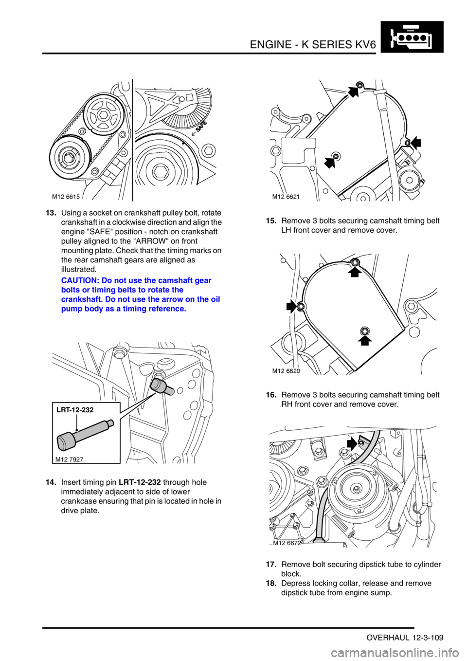
13.Using a socket on crankshaft pulley bolt, rotate
crankshaft in a clockwise direction and align the
engine "SAFE" position - notch on crankshaft
pulley aligned to the "ARROW" on front
mounting plate. Check that the timing marks on
the rear camshaft gears are aligned as
illustrated.
CAUTION: Do not use the camshaft gear
bolts or timing belts to rotate the
crankshaft. Do not use the arrow on the oil
pump body as a timing reference.
14.Insert timing pin LRT-12-232 through hole
immediately adjacent to side of lower
crankcase ensuring that pin is located in hole in
drive plate.15.Remove 3 bolts securing camshaft timing belt
LH front cover and remove cover.
16.Remove 3 bolts securing camshaft timing belt
RH front cover and remove cover.
17.Remove bolt securing dipstick tube to cylinder
block.
18.Depress locking collar, release and remove
dipstick tube from engine sump.
LRT-12-232
M12 7927
M12 6672
Page 289 of 1007
ENGINE - K SERIES KV6
12-3-112 OVERHAUL
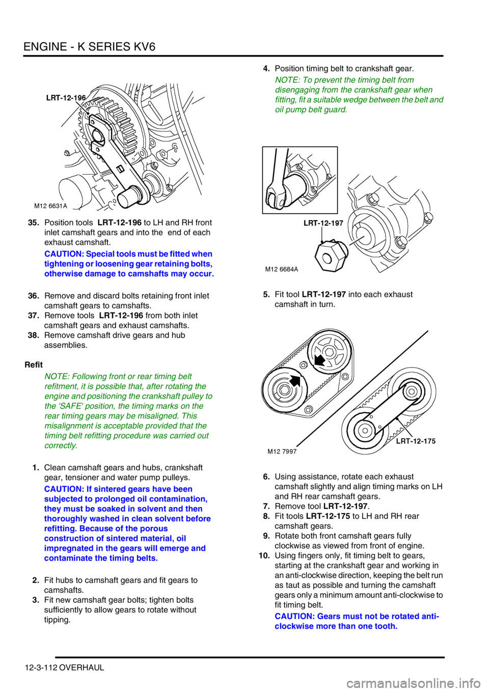
35.Position tools LRT-12-196 to LH and RH front
inlet camshaft gears and into the end of each
exhaust camshaft.
CAUTION: Special tools must be fitted when
tightening or loosening gear retaining bolts,
otherwise damage to camshafts may occur.
36.Remove and discard bolts retaining front inlet
camshaft gears to camshafts.
37.Remove tools LRT-12-196 from both inlet
camshaft gears and exhaust camshafts.
38.Remove camshaft drive gears and hub
assemblies.
Refit
NOTE: Following front or rear timing belt
refitment, it is possible that, after rotating the
engine and positioning the crankshaft pulley to
the 'SAFE' position, the timing marks on the
rear timing gears may be misaligned. This
misalignment is acceptable provided that the
timing belt refitting procedure was carried out
correctly.
1.Clean camshaft gears and hubs, crankshaft
gear, tensioner and water pump pulleys.
CAUTION: If sintered gears have been
subjected to prolonged oil contamination,
they must be soaked in solvent and then
thoroughly washed in clean solvent before
refitting. Because of the porous
construction of sintered material, oil
impregnated in the gears will emerge and
contaminate the timing belts.
2.Fit hubs to camshaft gears and fit gears to
camshafts.
3.Fit new camshaft gear bolts; tighten bolts
sufficiently to allow gears to rotate without
tipping.4.Position timing belt to crankshaft gear.
NOTE: To prevent the timing belt from
disengaging from the crankshaft gear when
fitting, fit a suitable wedge between the belt and
oil pump belt guard.
5.Fit tool LRT-12-197 into each exhaust
camshaft in turn.
6.Using assistance, rotate each exhaust
camshaft slightly and align timing marks on LH
and RH rear camshaft gears.
7.Remove tool LRT-12-197.
8.Fit tools LRT-12-175 to LH and RH rear
camshaft gears.
9.Rotate both front camshaft gears fully
clockwise as viewed from front of engine.
10.Using fingers only, fit timing belt to gears,
starting at the crankshaft gear and working in
an anti-clockwise direction, keeping the belt run
as taut as possible and turning the camshaft
gears only a minimum amount anti-clockwise to
fit timing belt.
CAUTION: Gears must not be rotated anti-
clockwise more than one tooth.
Page 315 of 1007

ENGINE MANAGEMENT SYSTEM - SIEMENS
18-3-10 REPAIRS
Sensor - throttle position (TP)
$% 18.30.17
Remove
1.Disconnect battery earth lead.
2.Remove acoustic cover.
+ ENGINE - K SERIES KV6, REPAIRS,
Cover - engine acoustic.
3.Disconnect multiplug from TP sensor.
4.Remove and discard 2 Torx screws and wave
washers securing TP sensor to inlet manifold.
5.Remove TP sensor specification plate.6.Pull TP sensor from throttle spindle.
CAUTION: Do not twist or apply leverage to
throttle position sensor.
Refit
1.Clean mating faces of throttle housing and TP
sensor.
2.Fit TP sensor to throttle spindle. Ensure that
during fitting the machined flat on the throttle
spindle is aligned with the mating portion of the
TP sensor
CAUTION: The throttle position sensor can
be easily damaged during fitting. When
pressing the sensor onto the throttle
spindle, use fingers only, and only apply
pressure to the area shown shaded in the
illustration.
3.Rotate TP sensor in an anti-clockwise direction
to align fixing holes.
CAUTION: Do not rotate throttle position
sensor in a clockwise direction and ensure
that it is not rotated beyond its internal
stops.
4.Fit TP sensor specification plate.
M18 0695
Page 342 of 1007

FUEL DELIVERY SYSTEM - PETROL
REPAIRS 19-2-21
Refit
1.Clean mating faces of IACV and throttle body.
2.Fit new gasket, position IACV to throttle body,
fit and tighten Allen screws to 6 Nm (4.5 lbf.ft).
3.Clean TP sensor and throttle body mating face.
4.Fit TP sensor to throttle spindle. Ensure that
during fitting the machined flat on the throttle
spindle is aligned with the mating portion of the
TP sensor
CAUTION: The throttle position sensor can
be easily damaged during fitting. When
pressing the sensor onto the throttle
spindle, use fingers only, and only apply
pressure to the area shown shaded in the
illustration.
5.Rotate TP sensor in an anti-clockwise direction
to align fixing holes.
CAUTION: Do not rotate throttle position
sensor in a clockwise direction and ensure
that it is not rotated beyond its internal
stops.
6.Fit TP sensor specification plate.
7.Fit new Torx screws and wave washers, tighten
Torx screws to 1.5 Nm _1.0 lbf.ft).
8. Vehicles with cruise control: Position
actuator support bracket to throttle body. Fit
Torx screws and tighten to 9 Nm (7 lbf.ft).
Connect actuator arm to throttle linkage.
9.Clean throttle body and mating face on inlet
manifold chamber.
10.Fit new seal to inlet manifold chamber.
11.Position throttle body to inlet manifold chamber,
fit and tighten Torx screws to 7 Nm ( 5 lbf.ft).
12.Connect multiplugs to TP sensor and IACV.
13. Vehicles with cruise control: Connect cruise
control actuator vacuum hose.
14.Connect primary throttle cable to throttle cam
and abutment bracket.
15.Connect engine breather/vacuum pipes to
throttle body and IACV.16.Adjust throttle cable.
+ FUEL DELIVERY SYSTEM -
PETROL, ADJUSTMENTS, Throttle cable -
check and adjust - KV6.
17.Connect battery earth lead.
18.Fit engine acoustic cover.
+ ENGINE - K SERIES KV6, REPAIRS,
Cover - engine acoustic.
19.Retune using TestBook
M18 0695
Page 361 of 1007
FUEL DELIVERY SYSTEM - PETROL
19-2-40 REPAIRS
Refit
1.Remove protective caps from each injector.
2.Clean injectors and recesses in fuel rail and
inlet manifold.
3.Lubricate new 'O' ring with castor oil and fit to
injector.
4.Fit injectors to fuel rail and secure with spring
clips.
5.Position fuel rail assembly and connect injector
multiplugs.
6.Fit injector spacer.
7.Push each injector into inlet manifold.
8.Fit bolts securing fuel rail to inlet manifold and
tighten to 8 Nm ( 6 lbf.ft).
9.Connect fuel feed hose to fuel rail.
10.Fit engine oil dipstick.
11.Connect vacuum pipe to fuel pressure regulator
and secure with clip.
12.Connect battery earth lead.
Actuator unit - cruise control - KV6 - non
NAS
$% 19.75.05
Remove
1.Disconnect battery earth lead.
2.Remove engine acoustic cover.
+ ENGINE - K SERIES KV6, REPAIRS,
Cover - engine acoustic.
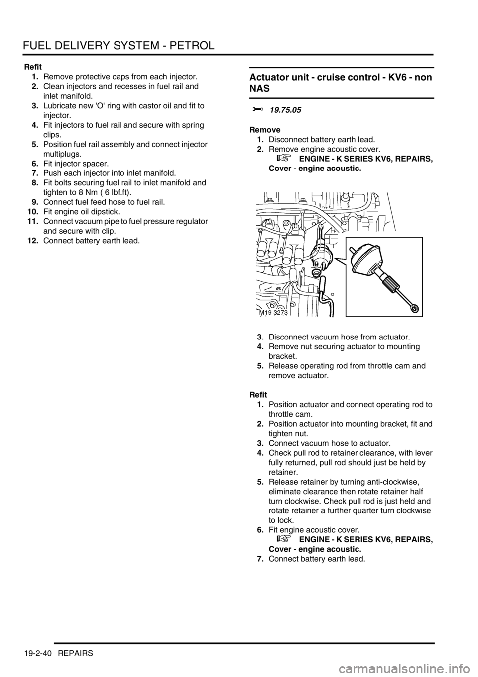
3.Disconnect vacuum hose from actuator.
4.Remove nut securing actuator to mounting
bracket.
5.Release operating rod from throttle cam and
remove actuator.
Refit
1.Position actuator and connect operating rod to
throttle cam.
2.Position actuator into mounting bracket, fit and
tighten nut.
3.Connect vacuum hose to actuator.
4.Check pull rod to retainer clearance, with lever
fully returned, pull rod should just be held by
retainer.
5.Release retainer by turning anti-clockwise,
eliminate clearance then rotate retainer half
turn clockwise. Check pull rod is just held and
rotate retainer a further quarter turn clockwise
to lock.
6.Fit engine acoustic cover.
+ ENGINE - K SERIES KV6, REPAIRS,
Cover - engine acoustic.
7.Connect battery earth lead.
Page 438 of 1007
AUTOMATIC GEARBOX - JATCO
ADJUSTMENTS 44-3
Selector cable - adjust
$% 44.30.04
Adjust
1.Remove underbelly panel.
+ EXTERIOR FITTINGS, REPAIRS,
Panel - underbelly.
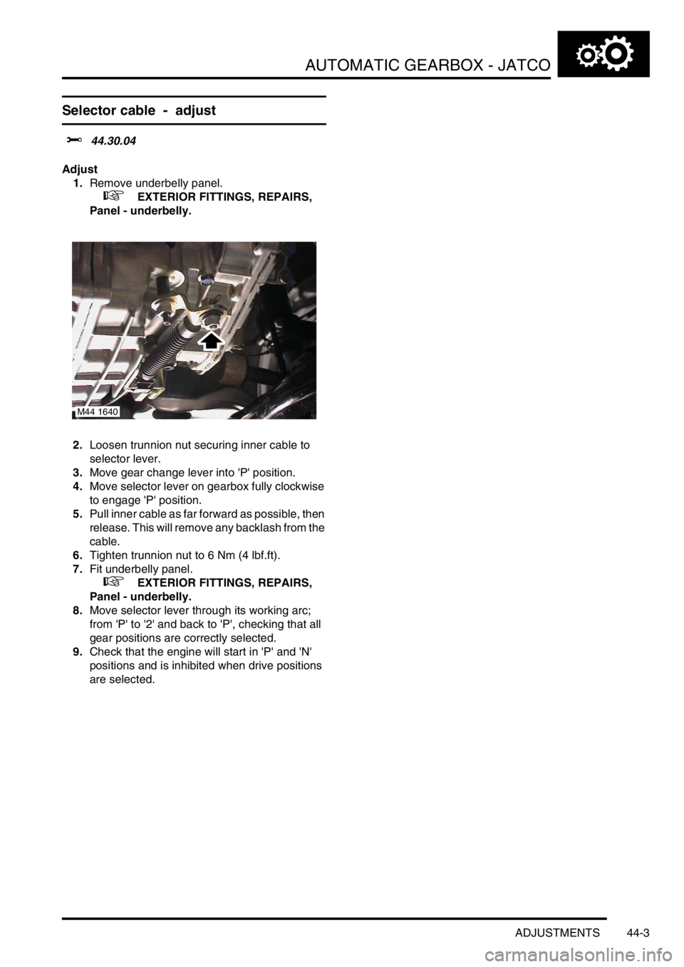
2.Loosen trunnion nut securing inner cable to
selector lever.
3.Move gear change lever into 'P' position.
4.Move selector lever on gearbox fully clockwise
to engage 'P' position.
5.Pull inner cable as far forward as possible, then
release. This will remove any backlash from the
cable.
6.Tighten trunnion nut to 6 Nm (4 lbf.ft).
7.Fit underbelly panel.
+ EXTERIOR FITTINGS, REPAIRS,
Panel - underbelly.
8.Move selector lever through its working arc;
from 'P' to '2' and back to 'P', checking that all
gear positions are correctly selected.
9.Check that the engine will start in 'P' and 'N'
positions and is inhibited when drive positions
are selected.
M44 1640
Page 504 of 1007
STEERING
REPAIRS 57-11
Drive belt - K1.8
$% 57.20.02
Remove
1.Disconnect battery earth lead.
2.Turn steering on RH lock.
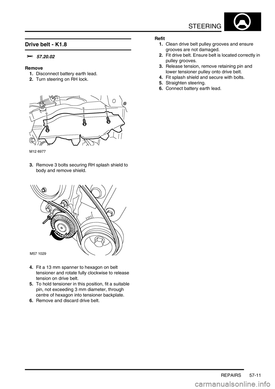
3.Remove 3 bolts securing RH splash shield to
body and remove shield.
4.Fit a 13 mm spanner to hexagon on belt
tensioner and rotate fully clockwise to release
tension on drive belt.
5.To hold tensioner in this position, fit a suitable
pin, not exceeding 3 mm diameter, through
centre of hexagon into tensioner backplate.
6.Remove and discard drive belt.Refit
1.Clean drive belt pulley grooves and ensure
grooves are not damaged.
2.Fit drive belt. Ensure belt is located correctly in
pulley grooves.
3.Release tension, remove retaining pin and
lower tensioner pulley onto drive belt.
4.Fit splash shield and secure with bolts.
5.Straighten steering.
6.Connect battery earth lead.
Page 600 of 1007
RESTRAINT SYSTEMS
REPAIRS 75-19
Rotary coupler - (SRS) air bag system
$% 76.74.20
Remove
WARNING: It is imperative that before any
work is undertaken on the SRS system the
appropriate information is read thoroughly.
1.Make the SRS system safe.
+ GENERAL INFORMATION,
Supplementary restraint system
precautions.
CAUTION: Before disconnecting any part of
the steering linkage, ensure the road wheels
are positioned straight ahead and the
steering wheel is prevented from turning.
Unrestricted turning of the steering wheel
will damage the SRS rotary coupler.
2.Remove steering wheel.
+ STEERING, REPAIRS, Steering
wheel.
CAUTION: Use adhesive tape to prevent
rotation of the rotary coupler once the
steering wheel is removed.
3.Remove steering column nacelle.
+ STEERING, REPAIRS, Nacelle -
column.
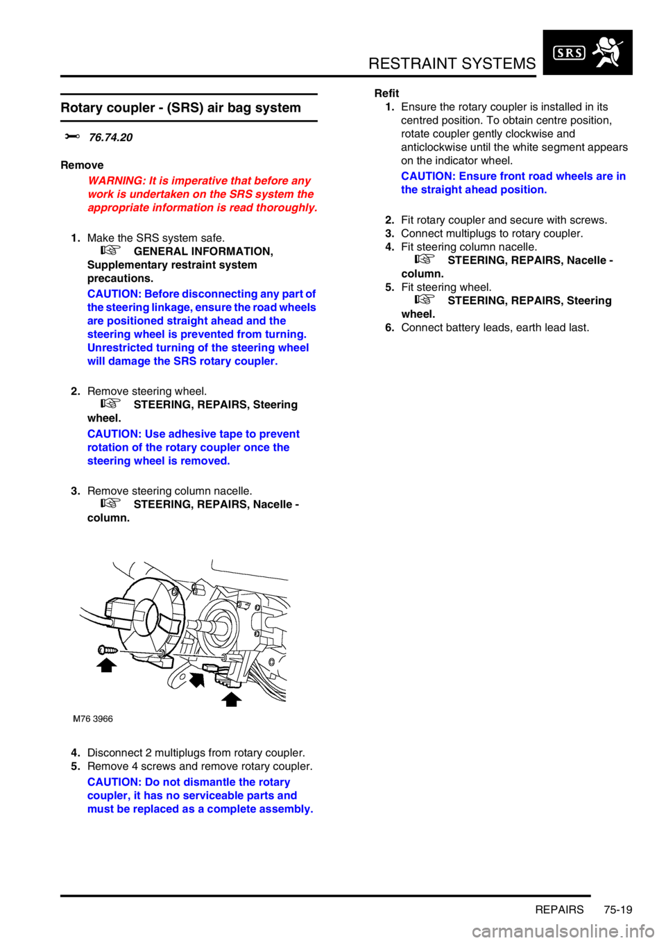
4.Disconnect 2 multiplugs from rotary coupler.
5.Remove 4 screws and remove rotary coupler.
CAUTION: Do not dismantle the rotary
coupler, it has no serviceable parts and
must be replaced as a complete assembly.Refit
1.Ensure the rotary coupler is installed in its
centred position. To obtain centre position,
rotate coupler gently clockwise and
anticlockwise until the white segment appears
on the indicator wheel.
CAUTION: Ensure front road wheels are in
the straight ahead position.
2.Fit rotary coupler and secure with screws.
3.Connect multiplugs to rotary coupler.
4.Fit steering column nacelle.
+ STEERING, REPAIRS, Nacelle -
column.
5.Fit steering wheel.
+ STEERING, REPAIRS, Steering
wheel.
6.Connect battery leads, earth lead last.
Page 617 of 1007
DOORS
76-1-12 REPAIRS
Glass regulator - tail door
$% 76.31.65
Remove
1.Remove rear screen.
+ DOORS, REPAIRS, Glass - tail door.
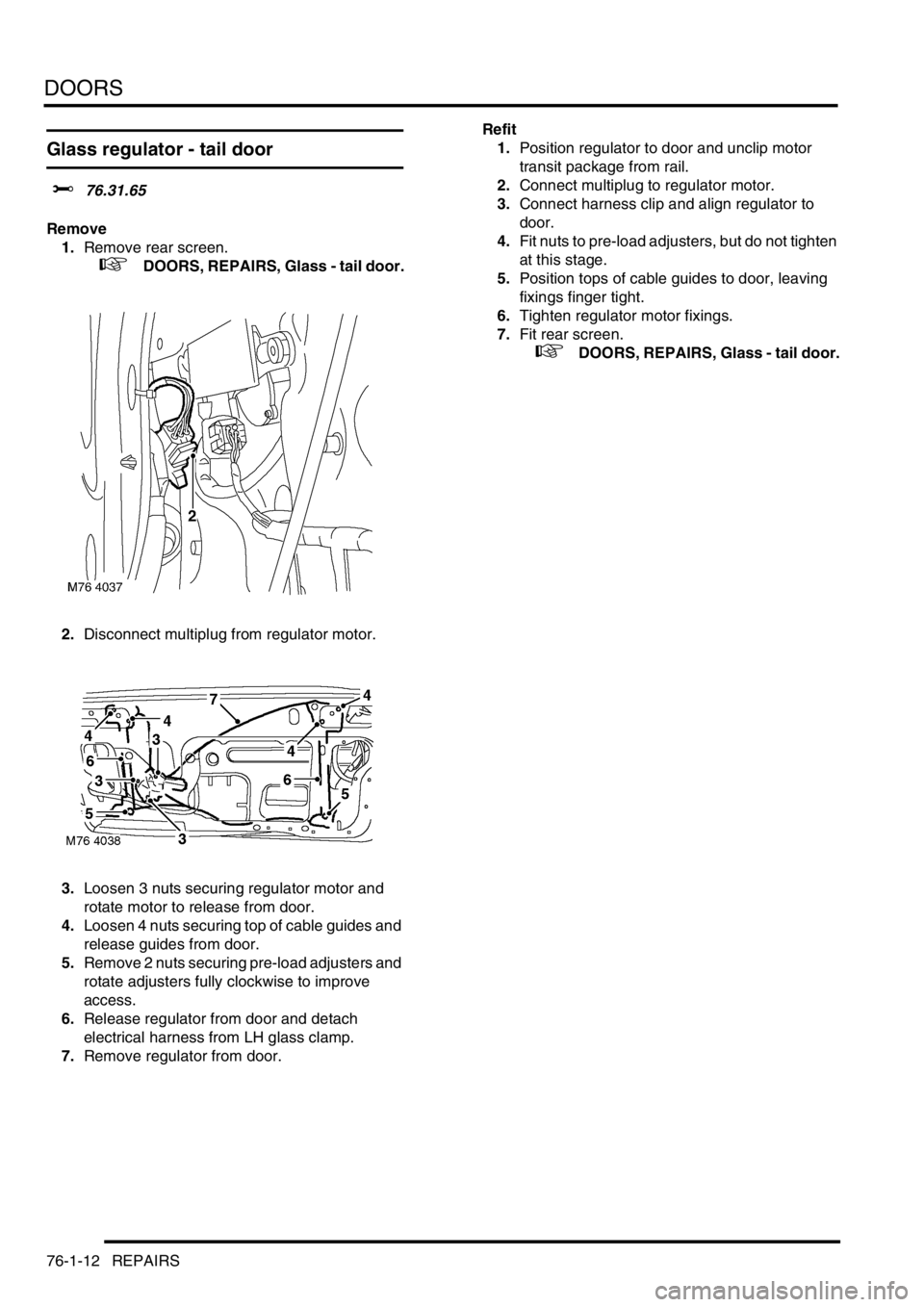
2.Disconnect multiplug from regulator motor.
3.Loosen 3 nuts securing regulator motor and
rotate motor to release from door.
4.Loosen 4 nuts securing top of cable guides and
release guides from door.
5.Remove 2 nuts securing pre-load adjusters and
rotate adjusters fully clockwise to improve
access.
6.Release regulator from door and detach
electrical harness from LH glass clamp.
7.Remove regulator from door.Refit
1.Position regulator to door and unclip motor
transit package from rail.
2.Connect multiplug to regulator motor.
3.Connect harness clip and align regulator to
door.
4.Fit nuts to pre-load adjusters, but do not tighten
at this stage.
5.Position tops of cable guides to door, leaving
fixings finger tight.
6.Tighten regulator motor fixings.
7.Fit rear screen.
+ DOORS, REPAIRS, Glass - tail door.
Page 675 of 1007
INTERIOR TRIM COMPONENTS
76-3-14 REPAIRS
Fascia - up to 04MY
$% 76.46.23
Remove
1.Remove front console.
+ INTERIOR TRIM COMPONENTS,
REPAIRS, Console - front - up to 04MY.
2.Remove rotary coupler.
+ RESTRAINT SYSTEMS, REPAIRS,
Rotary coupler - (SRS) air bag system.
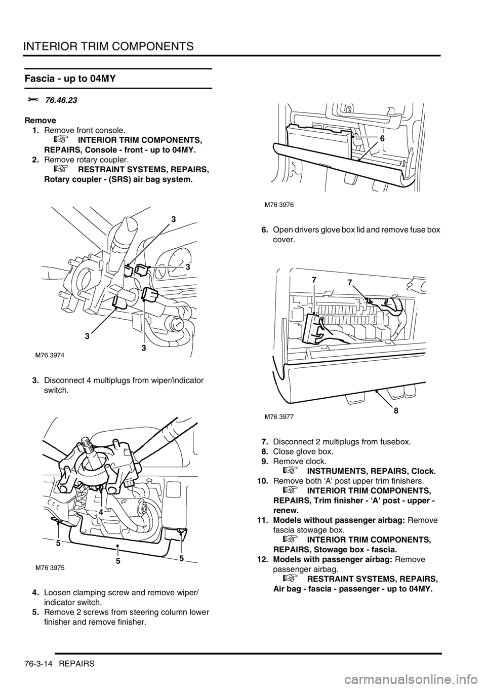
3.Disconnect 4 multiplugs from wiper/indicator
switch.
4.Loosen clamping screw and remove wiper/
indicator switch.
5.Remove 2 screws from steering column lower
finisher and remove finisher.6.Open drivers glove box lid and remove fuse box
cover.
7.Disconnect 2 multiplugs from fusebox.
8.Close glove box.
9.Remove clock.
+ INSTRUMENTS, REPAIRS, Clock.
10.Remove both 'A' post upper trim finishers.
+ INTERIOR TRIM COMPONENTS,
REPAIRS, Trim finisher - 'A' post - upper -
renew.
11. Models without passenger airbag: Remove
fascia stowage box.
+ INTERIOR TRIM COMPONENTS,
REPAIRS, Stowage box - fascia.
12. Models with passenger airbag: Remove
passenger airbag.
+ RESTRAINT SYSTEMS, REPAIRS,
Air bag - fascia - passenger - up to 04MY.